Burning The Bootloader (new Microcontroller)
This tutorial explains how to migrate from an Arduino board to a standalone microcontroller on a breadboard. It's similar to this tutorial, but uses an Arduino board to program the ATmega on the breadboard.
Unless you choose to use the minimal configuration described at the end of this tutorial, you'll need four components (besides the Arduino, ATmega328, and breadboard):
- a 16 MHz crystal,
- a 10k resistor, and
- two 18 to 22 picofarad (ceramic) capacitors.
Note that these techniques only work with the Arduino Duemilanove w/ an ATmega328, not the Arduino Uno (or older Arduino boards w/ an ATmega168).
Burning the Bootloader
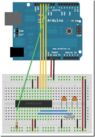
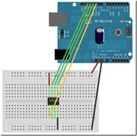
Using an Arduino board to burn the bootloader onto an ATmega on a breadboard.
If you have a new ATmega328 (or ATmega168), you'll need to burn the bootloader onto it. You can do this using an Arduino board as an in-system program (ISP). If the microcontroller already has the bootloader on it (e.g. because you took it out of an Arduino board or ordered an already-bootloadedATmega), you can skip this section.
To burn the bootloader, follow these steps:
1. Upload the ArduinoISP sketch onto your Arduino board. (You'll need to select the board and serial port from the Tools menu that correspond to your board.)
2. Wire up the Arduino board and microcontroller as shown in the diagram to the right.
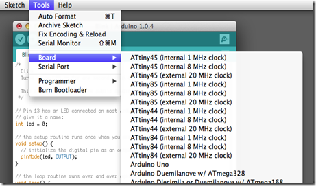
3. Select "Arduino Duemilanove or Nano w/ ATmega328" from the Tools > Board menu. (Or "ATmega328 on a breadboard (8 MHz internal clock)" if using the minimal configuration described below.)
4. Run Tools > Burn Bootloader > w/ Arduino as ISP.
You should only need to burn the bootloader once. After you've done so, you can remove the jumper wires connected to pins 10, 11, 12, and 13 of the Arduino board.
Programming via The Arduino Board
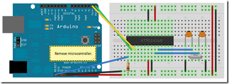
Once your ATmega328p has the Arduino bootloader on it, you can upload programs to it using the USB-to-serial convertor (FTDI chip) on an Arduino board. To do, you remove the microcontroller from the Arduino board so the FTDI chip can talk to the microcontroller on the breadboard instead. The diagram at right shows how to connect the RX and TX lines from the Arduino board to the ATmega on the breadboard. To program the microcontroller, select "Arduino Duemilanove or Nano w/ ATmega328" from the the Tools > Board menu (or "ATmega328 on a breadboard (8 MHzinternal clock)" if you're using the minimal configuration described below). Then upload as usual.
Uploading sketches to an ATmega on a breadboard. Remember to remove the microcontroller from the Arduino board!
Minimal Circuit (Eliminating the External Clock)
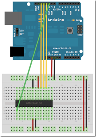
If you don't have the extra 16 MHz crystal and 18-22 picofarad capacitors used in the above examples, you can configure the ATmega328 to use its internal 8 MHz RC oscillator as a clock source instead. (You don't really need the 10K pullup resistor on the reset pin either, so we remove it to get a truly minimal configuration.)
You'll need to install support for an additional hardware configuration:
1. Download this hardware configuration archive: Breadboard.zip
2. Create a "hardware" sub-folder in your Arduino sketchbook folder (whose location you can find in the Arduino preferences dialog). If you've previously installed support for additional hardware configuration, you may already have a "hardware" folder in your sketchbook.
3. Move the "breadboard" folder from the zip archive to the "hardware" sub-folder of your Arduino sketchbook.
4. Restart the Arduino software.
5. You should see "ATmega328 on a breadboard (8 MHz internal clock)" in the Tools > Board menu.
Once you've done this, you can burn the bootloader and upload programs onto your ATmega328 as described above. Be sure to select "ATmega328 on a breadboard (8 MHz internal clock)" when burning the bootloader. (If you select the wrong item and configure the microcontroller to use an external clock, it won't work unless you connect one.)
Using an Arduino board to burn the bootloader onto an ATmega on a breadboard (w/o an external clock).
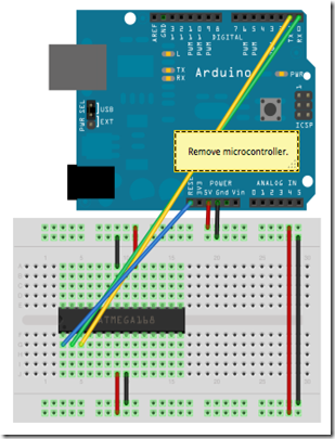
Uploading sketches to an ATmega on a breadboard.
Getting Rid of the Arduino Board
Once you've programmed the ATmega on the breadboard, you can eliminate the Arduino. To do so, you'll need to provide an alternative power supply for the microcontroller.
Now we will show you how to build an Arduino compatible breadboard with an Atmel Atmega8/168/328 AVR microcontroller and FTDI FT232 breakout board from SparkFun. You could also use the Arduino USB Mini.
Originally created David A. Mellis
Updated from the ITP version by Carlyn Maw
Updated October 23, 2008 by Rory Nugent
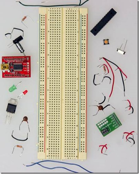
Parts
To do this, you'll need:
Basic Parts for wiring up Arduino
- A breadboard
- 22 AWG wire
- 7805 Voltage regulator
- 2 LEDs
- 2 220 Ohm resistors
- 1 10k Ohm resistor
- 2 10 uF capacitors
- 16 MHz clock crystal
- 2 22 pF capacitors
- small momentary normally open ("off") button, i.e. Omron type B3F
USB to Serial Communication Board
You will need a FT232 USB Breakout board from SparkFun.
There are two options available from them:
If you plan to use the top option and have not yet soldered headers to the breakout board, now would be a good time.
Bootloading your Atmega Chips
There are several options for bootloading your Atmega chips, a few of which are covered in this tutorial. If you wish to bootload your Atmega chips using your breadboard, an additional part will make your life much easier but is not necessary.
AVR Programming Adapter from Sparkfun, SKU BOB-08508
Adding circuitry for a power supply
If you've already worked with microcontrollers, it is likely that you already have a preferred way to wire up a power supply to your board, so go ahead and do it that way. In case you need some reminders, here are some pictures of one way to go about it. (This version uses a 5V regulated power supply)
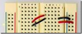
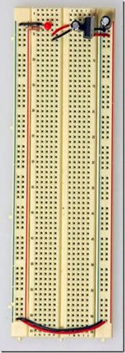
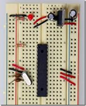
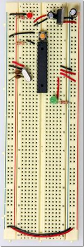
Add power and ground wires for where your voltage regulator will be.
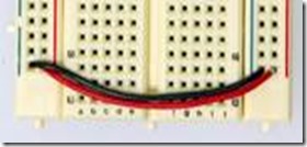
Add power and ground wires at the bottom of your board connecting each rail.
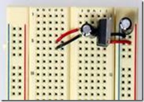
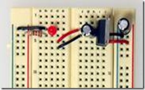
Add the 7805 and decoupling capacitors
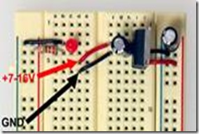
Add the 7805 power regulator and the lines to power the board. The regulator is a TO-220 package where the Input from the external power supply goes input on the left, ground is in the middle and the 5V output is on the right (when facing the front of the regulator). Add power OUT and ground wires that connect to the right and left rails of the breadboard.
Also, add a 10uF capacitor between the IN of the regulator and the ground as well as a 10uF capacitor on the right rail between power and ground. The silver strip on the capacitor signifies the ground leg.
Add an LED and a 220-ohm resistor on the left side of your board across from the voltage regulator. An LED attached to power like this is a great troubleshooting trick. You'll always know when your board is being powered as well as quickly know if your board is being shorted.
The red and black wires to the left of the voltage regulator is where your power supply will be plugged in. The red wire is for the POWER and the black wire is for the GROUND. Be sure to only attach a power supply that is between 7-16V. Any lower and you won't get 5V out of your regulator. Any higher and your regulator may be damaged. A 9V battery, 9V DC power supply, or 12V DC power supply is suitable.
Now that the power-basics are done you are ready to load on the chip!
ATMEGA8/168/328 Basics
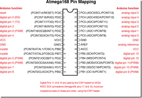
Before moving on, check out this image. It's a great resource for learning what each of the pins on your Atmega chip do in relation to the Arduino's functions. This will clarify a lot of confusion behind why you hook up certain pins the way you do. For even more detailed information, take a peek at the datasheet for the Atmega 168 (short version) (long version). Here's the sheet for the atmega328 (short version) (long version)
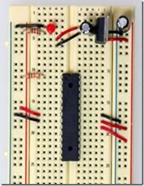
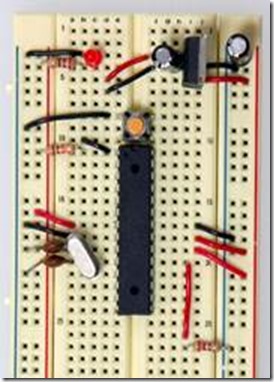
Start by connecting a 10k ohm pullup resistor to +5V from the RESET pin in order to prevent the chip from resetting itself during normal operation. The RESET pin reboots the chip when pulled down to ground. In later steps we will show you how to add a reset switch that takes advantage of this.
- Pin 7 - Vcc - Digital Supply Voltage
- Pin 8 - GND
- Pin 22 - GND
- Pin 21 - AREF - Analog reference pin for ADC
- Pin 20 - AVcc - Suppply voltage for the ADC converter. Needs to be connected to power if ADC isn't being used and to power via a low-pass filter if it is (a low pass filter is a circuit that reduces noise from the power source. This example isn't using one)
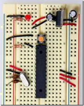
Add a 16 MHz external clock between pin 9 and 10, and add two 22 pF capacitors running to ground from each of those pins.
Add the small tactile switch so that you can reset the Arduino whenever we'd like and prepare the chip for uploading a new program. A quick momentary press of this switch will reset the chip when needed. Add the switch just above the top of the Atmega chip crossing the gap in the breadboard. Then, add a wire from the bottom left leg of the switch to the RESET pin of the Atmega chip and a wire from the top left leg of the switch to ground.
The chip used on this board is actually already programmed using the blink_led program that comes with the Arduino software. If you already have an Arduino printed circuit board running, it is a good idea to go ahead and check the breadboard version you are building with a chip you know works. Pull the chip from your working Arduino and try it on this board. The blink_led program blinks pin 13. Pin 13 on the Arduino is NOT the AVR ATMEGA8-16PU/ATMEGA168-16PU pin 13. It is actually pin 19 on the Atmega chip.
Refer to the pin mapping above to be sure you are plugging it in correctly.
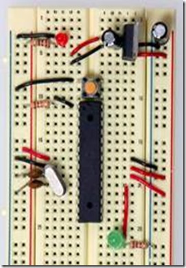
Finally, add the LED. The long leg or the anode connects to the red wire and the short leg or the cathode connects to the 220 ohm resistor going to ground.
At this point if you had already programmed your chip somewhere else and didn't need this breadboard circuit to reprogram the chip, you could stop here. But part of the fun is in-circuit programming so keep going to really make a full USB-Arduino-circuit on a breadboard!
Going All The Way – Full Blown Arduino
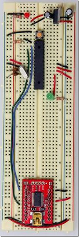
Now we'll be adding the USB to Serial breakout board to our Arduino breadboard circuit. If you haven't added male headers to your breakout board, you will need to do it now.
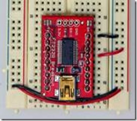
Connect the VCCIO of the breakout board to power and the GND to ground.
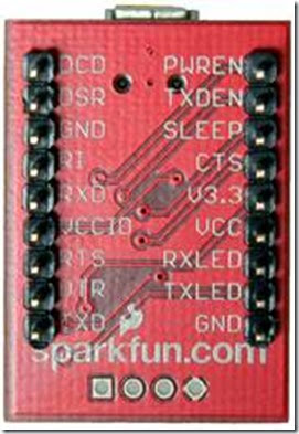
The pinouts of the Sparkfun FT232 breakout
Curious what all the pin outs are for the SparkFun FT232 breakout board, just simply flip it over! In this situation we'll be using VCC (to supply 5V from the USB port to your board), GND, TXD, and RXD.
Now, it's time to get the USB to serial breakout board talking with your new Arduino setup. Connect the RX (pin 2) of your Atmega chip to the TX of the USB to serial board, and connect the TX (pin 3) of your Atmega chip to the RX of the USB to serial board.
And there you have it... ready to be plugged in, powered up and programmed!
Base On:
