Sunday, August 30, 2015

Linux – SSH Reverse Tunnel to Bypass NAT

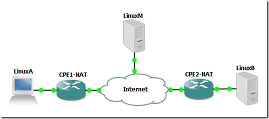
Have you ever wanted to reach a server via some application, for example ssh, but you couldn’t because the remote computer (LinuxB) was beind NAT, and you didn’t had access to the router (CPE2-NAT) to add a port forwarding:Top_Prob

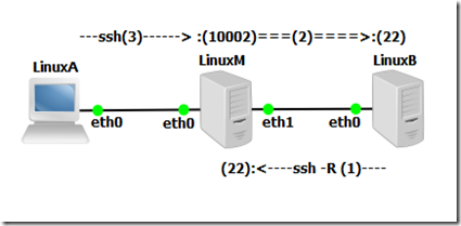
but if you add another server with a Public IP (LinuxM) in the midlle you can set up a Reverse SSH Tunel between the destination (LinuxB) and the server in the middle (LinuxM) that will forward conection to a local port on LinuxM to the destination port  on LinuxB via the established ssh session that has the reverse/remote tunel configured.

Top_Solution

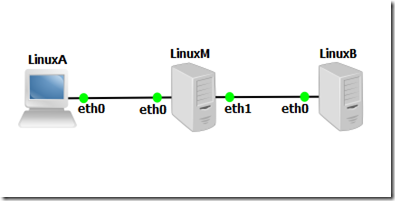
To test the Reverse SSH Tunel to bypass NAT I’m going to do a proof of concept (POC), with some linux (Ubuntu) machines with private addressing, the cenario looks like this:

Topologia_POC1


Linux_M – Middleman
===========================================================

## Hostname ##
sudo nano /etc/hostname
LinuxM
hostname LinuxM
hostname

sudo nano /etc/hosts
127.0.1.1       LinuxM


## Interfaces ##
sudo ifdown eth0                                                                 
sudo ifconfig eth0 192.168.1.254 netmask 255.255.255.0
sudo ifup eth0                                      

sudo ifdown eth1                                                                 
sudo ifconfig eth1 172.16.1.254 netmask 255.255.255.0
sudo ifup eth1


## IP Forwarding (Routing) ##
sudo  sysctl -w net.ipv4.ip_forward=1


## Activate Gateway Ports ##
sudo nano /etc/ssh/sshd_config
GatewayPorts yes
sudo service ssh stop
sudo service ssh start

#####################################################
# When you forward a TCP port (either locally or
# remotely), by default SSH only listens for
# connections to the forwarded port on the loopback
# address (localhost, 127.0.0.1). This means only
# other programs running on the same host as the
# listening side of the forwarding can connect to
# the forwarded port. This is a security feature,
# since there is no authentication applied to such
# connections. Also, such a forwarded connection is
# potentially insecure, since a portion of it is
# carried over the network in a plain TCP connection
# and not protected by SSH.
#####################################################


Linux_B – Destination
===========================================================

## Hostname ##
sudo nano /etc/hostname
LinuxB
hostname LinuxB
hostname

sudo nano /etc/hosts
127.0.1.1       LinuxB


## Interface ##
sudo ifdown eth0                                                                 
sudo ifconfig eth0 172.16.1.1 netmask 255.255.255.0
sudo ifup eth0


## Route (default) ##
sudo route add default gw 172.16.1.254 eth0


## Reverse/Remote SSH Tunnel ##
ssh -R 10002:localhost:22 lubuntu@172.16.1.254

######################################################
# This sets up the reverse/remote ssh tunnel
# between the destination (LinuxB) and the server
# in the middle (LinuxM) that will forward connection
# on the local port 10002 on LinuxM to the
# destination port 22 LinuxB via the established
# ssh session that has the reverse/remote tunel
# configured.
#
# After this command you will have the reverse/remote
# ssh thunnel configured and the bash/CLI of LinuxM.
#
# YOU MUST MAINTAIN THE BASH/CLI OF LinuxM ON LinuxB
# VIA SSH, FOR THE FORWARDING/TUNNELING TO WORK
#####################################################

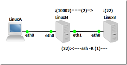
At this point you have this:

Topologia_POC2

the reverse/remote ssh tunnel wating for a connection on LinuxM on port 10002 to forward LinuxB on port 22 (ssh)


Linux_A – Client
===========================================================

## Hostname ##
sudo nano /etc/hostname
LinuxA
hostname LinuxA
hostname

sudo nano /etc/hosts
127.0.1.1       LinuxA

 
## Interface ##
sudo ifdown eth0                                                                 
sudo ifconfig eth0 192.168.1.1 netmask 255.255.255.0
sudo ifup eth0


## Route (default) ##
sudo route add default gw 192.168.1.254 eth0   


## Connect LinuxM (will forward to LinuxB) ##
## Gateway Ports = ON on LinuxM                ##

ssh lubuntu@192.168.1.254 -p 10002

or

## Connect LinuxM (will not forward to LinuxB) ##
## Gateway Ports = OFF on LinuxM                      ##

ssh lubuntu@192.168.1.254         
ssh lubuntu@localhost -p 10002

######################################################
# Assuming the "Gateway Ports" is OFF, then the
# reverse/remote ssh tunnel will only be accessible
# on LinuxM locally
#
# So in the above commands we first connect via SSH
# to LinuxM, and from there connect local ports of the
# reverse/remote ssh tunnel so that it will forward
# the connection on the local port 10002 of LinuxM
# to the destination port 22 LinuxB
#####################################################

At this point you have this (Gateway Ports = ON):

Topologia_POC3 and you should be in the bash/CLI of LinuxB Sorriso


Related Links:


Friday, August 28, 2015

Linux - Sending Email Alerts with Cron

Sending Email Alerts Through Cron

Cron is the Linux task scheduler that is responsible for making sure scripts run at their specified times. Cron is often used for things like, log rotation, backup scripts, updating file indexes, and running custom scripts. In the event a task runs into problems or errors Cron generally tries to email the local administrator of the machine. This means it tries to send an email to itself instead of an “internet accessible” email address like, ‘user@gmail.com’.

We can change this default behavior by changing the MAILTO variable.

Note: This will not work if you have not setup an email server.


Setting The Email Sending (Gmail and sSMTP)

Sometimes we want to enable our servers/desktops to be able to send email without setting up a full featured mail server or configuring postfix to route through Gmail.

sSmtp is an extremely simple, resource conserving, SMTP server that will allow your desktop or server to send email. In this article we are going to use sSMTP to send outgoing email through Gmail.


Install sSMTP

Debian/Ubuntu users can Install with this command or click here to open up apt:

sudo apt-get install ssmtp

We need to then need to edit, ‘/etc/ssmtp/ssmtp.conf’:

root=username@gmail.com mailhub=smtp.gmail.com:587 rewriteDomain= hostname=username@gmail.com UseSTARTTLS=YES AuthUser=username AuthPass=password FromLineOverride=YES

Then add each account that you want to be able to send mail from by editing, ‘/etc/ssmtp/revaliases‘:

root:username@gmail.com:smtp.gmail.com:587 localusername:username@gmail.com:smtp.gmail.com:587


Now try sending an email

You can send an email through your favorite email client, like ‘mutt’, or type:

sudo ssmtp someemail@email.com

You will then type your message, hit enter and ‘ctrl+d

Now that you have a simple outgoing email server setup, you can do all sorts of neat things:

  • Configure cron jobs to send log reports to your email address
  • Alert you of all kinds of system changes
  • Send email alerts when your computer reaches a certain temperature
  • Send email through PHP, Python, Ruby, and Perl


Setting the MAILTO variable

Cron relies on a simple text file to schedule commands. To edit this file just issue the crontab command:

crontab -e

To change the MAILTO variable just add ‘MAILTO=username@domain.com’ into the crontab file.

It should look something like this:

clip_image001

Specify Email for Each Script

If we don’t want all output to go to the same email address we can specify the output of a particular script to go to a different email address:

59 */6 * * * script.sh | mail -s "Subject of Mail" someother@address.com


Email Alerts for All but One

If you have a specific script in your crontab that you don’t want output or errors emailed to you, simply add, ‘>/dev/null 2>&1’ to the end of the command.

59 */6 * * * script.sh >/dev/null 2>&1

To find out what else you can do with cron check out, Learning Cron by Example.


Based On:

Thursday, August 20, 2015

Cisco - Router / Switch as an HTTP Server

You can use your Cisco router / switch as a Web server, Cisco IOS routers have HTTP interface since IOS 11.2, in IOS 12.2(15)T it was enhanced with HTTP 1.1 Web server that offers Secure Socket Layer (SSL) Version 3.

Let’s test it out, I actually did this on a switch (cisco 3560)


First let’s check current root folder for the HTTP server, in order to get a reference to restore the HTTP root path later:

DSw1#show ip http server status
HTTP server status: Enabled
HTTP server port: 80
HTTP server authentication method: enable
HTTP server access class: 0
HTTP server base path: flash:/c3560-ipservicesk9-mz.150-1.SE/html
HTTP server help root:
Maximum number of concurrent server connections allowed: 16
Server idle time-out: 180 seconds
Server life time-out: 180 seconds
Maximum number of requests allowed on a connection: 25
HTTP server active session modules: ALL
HTTP secure server capability: Present
HTTP secure server status: Enabled
HTTP secure server port: 443
HTTP secure server ciphersuite: 3des-ede-cbc-sha des-cbc-sha rc4-128-md5 rc4-128-sha
HTTP secure server client authentication: Disabled
HTTP secure server trustpoint:
HTTP secure server active session modules: ALL

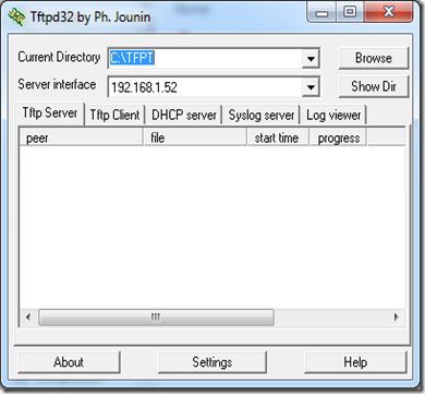
To transfer the web page we are going to use TFTP, for the server just run TFPT32 / TFTP64 in your computer, and point it to the folder where you have the web page you want to transfer to your router / switch.

1

On router / switch copy the web page from the TFTP server (your PC) to your router / switch:

DSw1#copy tftp://192.168.1.52/index.html flash://index.html
Destination filename [index.html]?
Accessing tftp://192.168.1.52/index.html...
Loading index.html from 192.168.1.52 (via Vlan99): !
[OK - 15772 bytes]

 
DSw1#show flash
Directory of flash:/
     2  -rwx       15772   Mar 1 1993 00:26:36 +00:00  index.html
      3  -rwx          1276   Mar 1 1993 00:00:40 +00:00  vlan.dat
  363  drwx         256   Mar 1 1993 00:39:23 +00:00  c3560-ipservicesk9-mz.150-1.SE
  487  -rwx        4189   Mar 1 1993 00:19:41 +00:00  config.text

Now in the golbal configuration mode lets enable the HTTP server, set the path to root folder of the HTTP server, and activate local authentication, and a local user and password (if you don’t already don’t have one)

ip http server
ip http path flash://
ip http authentication local

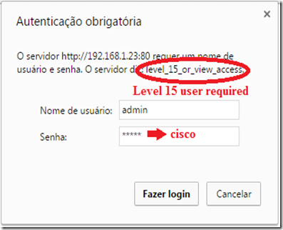
username admin privilege 15 password 0 cisco  (the user level must be 15)

you can also have HTTPS (secure) server using by adding the following command:

ip http secure-server

Here's a list of important commands you should know. These commands are in global configuration mode and have the format “ip http xxxxx”.

  • access-class: This restricts access to your Web server using an access list.
  • authentication: This sets the authentication for login to the Web server to either local, enable, or tacacs.
  • path: This establishes the root path where the Web server begins looking for files.
  • port: This allows you to change the port number for the Web server from 80 to another port.
  • server: This enables and disables the Web server.
  • secure-server: This enables and disables the SSL Web server.
          

Let’s check the new root folder for the HTTP server:
   
DSw1#show ip http server status
HTTP server status: Enabled
HTTP server port: 80
HTTP server authentication method: local
HTTP server access class: 0
HTTP server base path: flash:/
HTTP server help root:
Maximum number of concurrent server connections allowed: 16
Server idle time-out: 180 seconds
Server life time-out: 180 seconds
Maximum number of requests allowed on a connection: 25
HTTP server active session modules: ALL
HTTP secure server capability: Present
HTTP secure server status: Enabled
HTTP secure server port: 443
HTTP secure server ciphersuite: 3des-ede-cbc-sha des-cbc-sha rc4-128-md5 rc4-128-sha
HTTP secure server client authentication: Disabled
HTTP secure server trustpoint:
HTTP secure server active session modules: ALL


Now open your browser, and type:

http://<your_router_or_switch_ip_address>

03

you will be prompted for a local user and password, and you should get you web page shown:
    02

Based On: http://www.techrepublic.com/article/take-advantage-of-the-cisco-ios-web-server-on-your-router/

Wednesday, August 19, 2015

Cisco - DMVPN Explained + GNS3 Lab

DMVPN (dynamic multipoint virtual private network) is a design approach that allows full mesh connectivity with the use of multipoint GRE tunnels. DMVPN itself is not a protocol but rather it is a design approach that consists of the following technologies:

  1. NHRP (next-hop resolution protocol)
  2. mGRE(multipoint GRE)
  3. Routing protocol
  4. IP sec encryption (optional)

Most of these technologies are familiar to networking professionals, except for the NHRP protocol. NHRP is a resolution protocol that behaves like ARP. In an NHRP environment, there are two roles, the NHS (next-hop server) and the NHC (next-hop client). The NHCs register themselves with the NHS and provide information, such as their logical VPN IP addresses and the physical NBMA mapping. The NHCs also request information from the NHS about how to reach the other NHCs by learning the logical IP to NBMA mapping information. NHRP was used before in the legacy overlay VPN environment particularly in building frame-relay SVCs (switched virtual circuits). Today the protocol is used in the DMVPN environment as well using the same behavior.

DMVPN is typically deployed using MPLS and Internet services because DMVPN has the capability to build dynamic tunnels to other spokes or branches without going through the hub site. This makes efficient use of the full mesh topologies mentioned above. If DMVPN is deployed using the Internet, the hub router requires a static public IP address as this will be configured in the NHC routers as the NHS IP address. The spokes don’t require a static public IP address as a tunnel source because they will report their physical IP to logical mappings to the NHS or the hub. In an MPLS environment, using the IP address of the Loopback is an acceptable design. DMVPN provides zero-touch configuration on the hub router if a new spoke is added.

DMVPN has so far three phases of evolution: Phase 1 had only hub-and-spoke, in Phase 2 direct spoke-to-spoke capability for DMVPN was added, and Phase 3 has features that help a hierarchical DMVPN design scale better through the use of NHRP Shortcut and other enhancements. Our lab will focus on more on Phase 2.

In this GNS3 Lab, we will have the following tasks below. Verification will be done for each of the steps.

  1. Configure DMVPN on the hub router R1.
  2. Configure spokes R2, R3 and R4.
  3. Configure EIGRP as the routing protocol and enable spoke-to-spoke tunnels. Add Loopback10 to each of the routers and announce it in EIGRP.
  4. Configure encryption.

Below are the physical and logical diagrams.
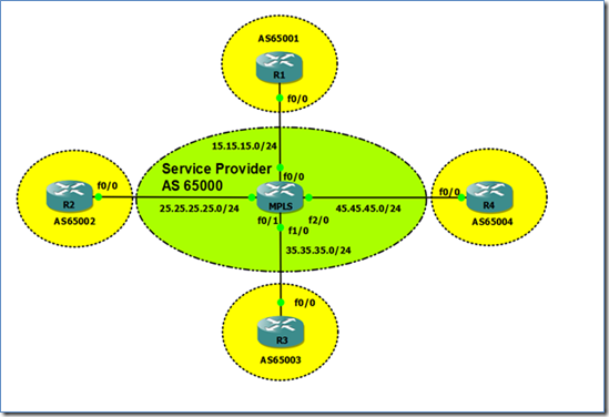
clip_image001

Figure 1. Network Topology

clip_image002

Figure 2. DMVPN Topology


Task 1: Configure DMVPN on the Hub Router R1

The MPLS router in the GNS3 topology has already been pre-configured to peer with all the routers using BGP. The routers in this topology are already announcing their Loopback0s through BGP. Before proceeding with the configuration, let’s check if we can see the loopback IP addresses of all the routers from R1.

R1#sh ip bgp
BGP table version is 5, local router ID is 1.1.1.1
Status codes: s suppressed, d damped, h history, * valid, > best, i - internal,
r RIB-failure, S Stale
Origin codes: i - IGP, e - EGP, ? - incomplete

Network Next Hop Metric LocPrf Weight Path
*> 1.1.1.1/32 0.0.0.0 0 32768 i
*> 2.2.2.2/32 15.15.15.5 0 65000 65002 i
*> 3.3.3.3/32 15.15.15.5 0 65000 65003 i
*> 4.4.4.4/32 15.15.15.5 0 65000 65004 i


Then we configure Tunnel100 with the DMVPN configuration for hub routers.

R1(config)#int tun100
R1(config-if)#ip add 10.1.1.1 255.255.255.0
R1(config-if)#ip nhrp map multicast dynamic
R1(config-if)#ip nhrp authentication cisco
R1(config-if)#ip nhrp network-id 100
R1(config-if)#tunnel source Loopback0
R1(config-if)#tunnel mode gre multipoint
R1(config-if)#tunnel key 100


Let’s break down the commands one by one.

  • ip nhrp map multicast dynamic: Normally this is configured in the hub routers to allow NHRP to automatically add routers to the multicast NHRP mappings so a static mapping is not required any more for each of the spokes. This command also enables routing protocols to work over the mGRE.
  • ip nhrp authentication <string>: This is an optional command. All the routers with NHRP within the same DMVPN network must have the same string or password.
  • ip nhrp network-id <number>: This is a required command to start NHRP. All routers in the same NHRP network should have the same network-id. This can also be used along with the “tunnel key” command to segregate different DMVPN networks using the same interface/ IP address as the tunnel source.
  • tunnel source Loopback0: This is the “physical” or real IP address which the tunnel should be sourced from. In the typical GRE configuration, a tunnel destination is required, but in DMVPN the tunnel destination is resolved through NHRP.
  • tunnel mode gre multipoint: Sets the GRE tunnel to behave as a multipoint tunnel.
  • tunnel key <number>” Like “ip nhrp network-id,” this allows separation of DMVPN networks using the same interface/ IP address as the source of the tunnel. This was mandatory in the previous IOS versions but, for the most recent ones, the DMVPN tunnel can come up without this command.


Task 2: Configure Spokes R2, R3 and R4

Let’s proceed to configure DMVPN on the spokes and explain each command later. The spokes will have a different command set than that of the hub.

R2(config)#interface Tunnel100
R2(config-if)# ip address 10.1.1.2 255.255.255.0
R2(config-if)# ip nhrp map multicast 1.1.1.1
R2(config-if)# ip nhrp map 10.1.1.1 1.1.1.1
R2(config-if)# ip nhrp nhs 10.1.1.1
R2(config-if)# ip nhrp network-id 100
R2(config-if)# ip nhrp registration timeout 60
R2(config-if)# ip nhrp holdtime 120
R2(config-if)# ip nhrp authentication cisco
R2(config-if)# tunnel source Loopback0
R2(config-if)# tunnel mode gre multipoint
R2(config-if)# tunnel key 100


R3(config)#interface Tunnel100
R3(config-if)# ip address 10.1.1.3 255.255.255.0
R3(config-if)# ip nhrp map multicast 1.1.1.1
R3(config-if)# ip nhrp map 10.1.1.1 1.1.1.1
R3(config-if)# ip nhrp nhs 10.1.1.1
R3(config-if)# ip nhrp network-id 100
R3(config-if)# ip nhrp registration timeout 60
R3(config-if)# ip nhrp holdtime 120
R3(config-if)# ip nhrp authentication cisco
R3(config-if)# tunnel source Loopback0
R3(config-if)# tunnel mode gre multipoint
R3(config-if)# tunnel key 100


R4(config)#interface Tunnel100
R4(config-if)# ip address 10.1.1.4 255.255.255.0
R4(config-if)# ip nhrp map multicast 1.1.1.1
R4(config-if)# ip nhrp map 10.1.1.1 1.1.1.1
R4(config-if)# ip nhrp nhs 10.1.1.1
R4(config-if)# ip nhrp network-id 100
R4(config-if)# ip nhrp registration timeout 60
R4(config-if)# ip nhrp holdtime 120
R4(config-if)# ip nhrp authentication cisco
R4(config-if)# tunnel source Loopback0
R4(config-if)# tunnel mode gre multipoint
R4(config-if)# tunnel key 100

Let’s break down and discuss each of the commands.

  • ip nhrp map multicast <1.1.1.1>: To put it simply, this command adds the NBMA address, in our case the loopback address of R1, to be a recipient of multicast/broadcast traffic coming from this spoke. The source IP address of the hub router’s DMVPN tunnel is configured as well as the other hub IP address if the design should go for multiple hubs.
  • ip nhrp map <10.1.1.1> <1.1.1.1>: To put it simply, this command states that 1.1.1.1 is the NBMA or real IP address of R1’s tunnel IP address of 10.1.1.1.
  • ip nhrp nhs <10.1.1.1>: This basically tells the router that the NHS is 10.1.1.1. This is the tunnel IP address of the hub router R1 in our example. The router will know who to consult to if it wishes to form a spoke-to-spoke tunnel. Multiple NHS configurations can be made if there are multiple hubs in the DMVPN network.

The rest of the NHRP commands are self-explanatory. The network-id and tunnel key in the spokes should match what is configured in the hub router.


Task 3: Configure EIGRP as the routing protocol and enable spoke-to-spoke tunnels. Add Loopback10 to each of the routers and announce it in EIGRP.

Let’s enable EIGRP and announce the DMVPN network. Any routing protocol can be used, but EIGRP or OSPF are favorable in most designs. One thing to look out for is that for DMVPN spoke-to-spoke to work and bypass the hub, the next-hop IP address of the route should be unchanged, meaning it should not be the IP address of the hub’s tunnel but should be the corresponding spoke tunnel IP address. In OSPF, changing the interface network type to “broadcast” is the solution. EIGRP requires split-horizon to be disabled and next-hop-self on the hub router.

R1(config-if)#interface Loopback10
R1(config-if)#ip address 11.11.11.11 255.255.255.255
!
R1(config)#router eigrp 100
R1(config-router)#no auto-summary
R1(config-router)#network 10.1.1.0 0.0.0.255
R1(config-router)#network 11.11.11.11 0.0.0.0.
!
R1(config-if)#int tun100
R1(config-if)#no ip split-horizon eigrp 100
R1(config-if)#no ip next-hop-self eigrp 100


R2(config)#int lo10
R2(config-if)#ip address 22.22.22.22 255.255.255.255
!
R2(config-if)#router eigrp 100
R2(config-router)#network 10.1.1.0 0.0.0.255
R2(config-router)#network 22.22.22.22 0.0.0.0


R3(config-if)#int l10
R3(config-router)#network 10.1.1.0 0.0.0.255
R3(config-if)#ip address 33.33.33.33 255.255.255.255
!
R3(config-if)#router eigrp 100
R3(config-router)#network 33.33.33.33 0.0.0.0


R4(config-if)#int l10
R4(config-router)#network 10.1.1.0 0.0.0.255
R4(config-if)#ip address 44.44.44.44 255.255.255.255
!
R4(config-if)#router eigrp 100
R4(config-router)#network 44.44.44.44 0.0.0.0


Let’s check and verify EIGRP neighbor adjacencies and routes:

R1#sh ip eigrp ne
IP-EIGRP neighbors for process 100
H Address Interface Hold Uptime SRTT RTO Q Seq
(sec) (ms) Cnt Num
2 10.1.1.4 Tu100 14 00:03:18 79 474 0 7
1 10.1.1.3 Tu100 12 00:04:42 76 456 0 6
0 10.1.1.2 Tu100 14 00:04:42 66 396 0 5

R1#sh ip route eigrp
33.0.0.0/32 is subnetted, 1 subnets
D 33.33.33.33 [90/14208000] via 10.1.1.3, 00:01:24, Tunnel100
22.0.0.0/32 is subnetted, 1 subnets
D 22.22.22.22 [90/14208000] via 10.1.1.2, 00:02:58, Tunnel100
44.0.0.0/32 is subnetted, 1 subnets
D 44.44.44.44 [90/14208000] via 10.1.1.4, 00:00:44, Tunnel100

Let’s check how many NHRP entries before we ping 44.44.44.44 from R2, using 22.22.22.22 as source. We will only see one static mapping which is going to R1, the NHS.

R2#sh ip nhrp
10.1.1.1/32 via 10.1.1.1, Tunnel100 created 00:12:55, never expire
Type: static, Flags: authoritative used
NBMA address: 1.1.1.1

We will now test if spoke-to-spoke is possible. Let’s trace from R2 to R4. Take note that in some cases the trace will go to R1 for the initial traffic. The succeeding packets will go directly to R4. The reason for this is that. when the initial traffic is sent, R2 is still in the process of getting information about how to reach R4 directly through NHRP.

R2#traceroute 44.44.44.44 source 22.22.22.22
Type escape sequence to abort.
Tracing the route to 44.44.44.44

1 10.1.1.4 36 msec 36 msec 36 msec

R2#sh ip route 44.44.44.44
Routing entry for 44.44.44.44/32
Known via "eigrp 100", distance 90, metric 27008000, type internal
Redistributing via eigrp 100
Last update from 10.1.1.4 on Tunnel100, 00:02:20 ago
Routing Descriptor Blocks:
* 10.1.1.4, from 10.1.1.1, 00:02:20 ago, via Tunnel100
Route metric is 27008000, traffic share count is 1
Total delay is 1005000 microseconds, minimum bandwidth is 2000 Kbit
Reliability 255/255, minimum MTU 1200 bytes
Loading 1/255, Hops 2

R2#sh ip nhrp
10.1.1.1/32 via 10.1.1.1, Tunnel100 created 00:14:45, never expire
Type: static, Flags: authoritative used
NBMA address: 1.1.1.1
10.1.1.4/32 via 10.1.1.4, Tunnel100 created 00:00:04, expire 00:01:14
Type: dynamic, Flags: router used
NBMA address: 4.4.4.4

The traceroute above shows that the path taken was directly to the tunnel IP address of R4. The “show ip nhrp” command showed as well that the R2 built a direct spoke-to-spoke to R4 and traffic did not pass through R1.


Task 4: Configure Encryption

A good network design includes a way to secure traffic. This is a must, given that DMVPN is deployed into shared topologies like internet and MPLS. Let’s proceed to configure IP sec encryption. We will begin with configuration of the IP sec policy, SA, and profiles.

On All Routers:

crypto isakmp policy 5
encr aes 256
group 2
authentication pre-share
!
crypto isakmp key 0 cisco address 0.0.0.0 0.0.0.0
!
crypto isakmp invalid-spi-recovery
crypto isakmp keepalive 10
!
crypto ipsec security-association lifetime kilobytes 536870912
crypto ipsec security-association replay disable
!
crypto ipsec transform-set DMVPN esp-aes 256 esp-sha-hmac comp-lzs
crypto ipsec df-bit clear
!
crypto ipsec profile DMVPN
set transform-set DMVPN

Then let’s apply the crypto IP sec profile as tunnel protection mode on the tunnels for each router.

R1(ipsec-profile)#int Tunnel100
R1(config-if)# tunnel protection ipsec profile DMVPN
R1(config-if)#end

R1#
*Mar 1 00:25:45.115: %CRYPTO-6-ISAKMP_ON_OFF: ISAKMP is ON
*Mar 1 00:25:45.191: %SYS-5-CONFIG_I: Configured from console by console
R1#
*Mar 1 00:25:45.731: %CRYPTO-4-RECVD_PKT_NOT_IPSEC: Rec'd packet not an IPSEC packet.
(ip) vrf/dest_addr= /1.1.1.1, src_addr= 2.2.2.2, prot= 47


R2(ipsec-profile)#int Tunnel100
R2(config-if)# tunnel protection ipsec profile DMVPN


R3(ipsec-profile)#int Tunnel100
R3(config-if)# tunnel protection ipsec profile DMVPN


R4(config)#int Tunnel100
R4(config-if)# tunnel protection ipsec profile DMVPN

The network adjacencies will be lost and will only recover until the configurations are complete for each router. Now, let’s verify if traffic is encrypted and network connectivity is still up.

R1#ping 22.22.22.22 source 11.11.11.11
Type escape sequence to abort.
Sending 5, 100-byte ICMP Echos to 22.22.22.22, timeout is 2 seconds:
Packet sent with a source address of 11.11.11.11
!!!!!
Success rate is 100 percent (5/5), round-trip min/avg/max = 52/62/76 ms

R1#ping 33.33.33.33 source 11.11.11.11
Type escape sequence to abort.
Sending 5, 100-byte ICMP Echos to 33.33.33.33, timeout is 2 seconds:
Packet sent with a source address of 11.11.11.11
!!!!!
Success rate is 100 percent (5/5), round-trip min/avg/max = 40/52/64 ms

R1#ping 44.44.44.44 source 11.11.11.11
Type escape sequence to abort.
Sending 5, 100-byte ICMP Echos to 44.44.44.44, timeout is 2 seconds:
Packet sent with a source address of 11.11.11.11
!!!!!
Success rate is 100 percent (5/5), round-trip min/avg/max = 64/80/100 ms

R1#sh crypto isakmp sa
dst src state conn-id slot status
1.1.1.1 3.3.3.3 QM_IDLE 2 0 ACTIVE
1.1.1.1 2.2.2.2 QM_IDLE 1 0 ACTIVE
1.1.1.1 4.4.4.4 QM_IDLE 3 0 ACTIVE

The “QM_IDLE” means that IP sec is working properly. EIGRP adjacencies are restored. Now we have successfully created a secure and encrypted DMVPN network.

References


Based On:

Monday, August 3, 2015

Windows - Downgrade From Windows 10 to 7 or 8.1

How to Downgrade from Windows 10 to Windows 7 or 8.1

clip_image001

Windows 10 combines the best of Microsoft’s previous operating systems and combines them into one ultimate package. If you opted in to the free upgrade and have changed your mind after running Windows 10 for a few days, you’ll be pleased to know that it’s easy to roll back.

Don’t worry if you didn’t consider this before you upgraded. Microsoft has made it easy to change back to your previous operating system for a limited period. But there are other options too, meaning if you really don’t like the Windows 10 experience, you’re not stuck with it permanently.

If you’re thinking of rolling back to Windows 7 or 8.1, please drop into the comments section afterwards to let us know why and which method you’ll be using.


Back Up Before You Downgrade

You should do this before upgrading to Windows 10. It’s incredibly important that you always back up your system before making any major change. Although some of the processes outlined below should keep your data in tact, nothing is ever definite and it’s not worth taking the risk.

clip_image002

If you have backed up recently and your data hasn’t changed much since, it could just be a case of copying over a few extra files. If you need to do a full backup, check out our guide on the safest ways to backup. I recommend something likeCrashPlan for the future because it’ll take regular backups of your system, which is a practice you should follow anyway.

Also, make sure you’re not backing up to the same drive that the operating system is installed on. This might mean you’ll have to use an external hard drive or online cloud storage, but a backup is not secure if it’s sitting in the same place as your original data.


Built-in Downgrade Option

When upgrading from a previous version of Windows to 10, your old operating system files will be stored in a folder called Windows.old. This can be removed to free up space, but its existence means that rollback is easy.

Windows 10 has a built-in feature that allows you to go back to your old operating system. The caveat is that this option is only available for one month after you’ve upgraded. If that time has passed, check out some of the other options available below.

clip_image003

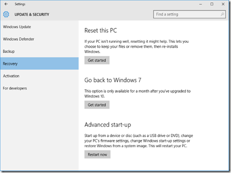
To get started, press Windows Key + I to bring up the Settings menu. ClickUpdate & security and then select Recovery from the left-hand navigation. Here you will see a header called Go back to Windows X (dependent on what version you were on before). Click Get started.

A window will open to ask while you’re going back to an old version. Fill this in and continue to click Next, noting the prompts and information like not unplugging your system during the process. The rollback will then begin, during which you won’t be able to use your system.

clip_image004

You might have to reinstall some programs or alter a couple of settings to get things back to how they were previously, but overall you should find it a quick and easy process.


Reinstall Your Previous Windows Version

Another method you could opt for is to do a fresh install of your old operating system. This will wipe everything on your drive, meaning the backup of personal data mentioned earlier is a required step before proceeding with this solution.

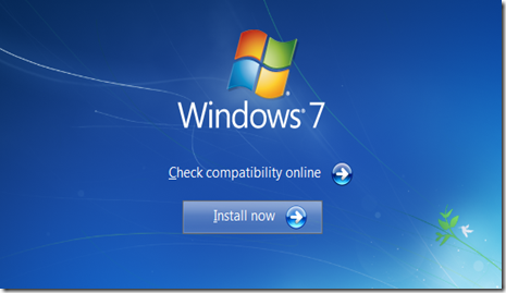
If you’ve got the previous Windows version on physical media, like a disc or USB drive, put it into your computer. If you don’t have a physical version then you can create one direct from Microsoft thanks to their Windows 7 Software Recovery andWindows 8.1 Installation Media. We have previously explained in detail how to created bootable Windows installation media.

clip_image005

Then restart your system and look for the message that’ll read something like “press F12 to choose boot device”. The message and key might vary – F10 and Esc are common alternatives. You can tap the key multiple times to make sure it’s registered.

You’ll then see a menu that will list all of the bootable devices to choose from. Use the arrow keys to select the one which corresponds to the media you just put in and then press Enter. Then follow the installation wizard, ensuring to select a custom install if prompted – this means you want to do a completely fresh install. You’ll be asked for your product license key, which can be found on the installation media (if Windows was purchased separately), or usually on a sticker on the device or with the PC’s documentation (if Windows came with the machine).


From a Drive Image

This one will only be applicable if you prepared ahead before upgrading to Windows 10. That is, if you have an image of your drive you can just restore that. An image is a complete copy of what’s on a drive, which includes personal data as well as the operating system’s files.

clip_image006

A drive image can be created in Windows 7 and 8.1 using the System Image utility (do a system search to find it), which can then be stored on external media. To restore from this in Windows 10, press Windows Key + I, click Update & security, then select Recovery. Underneath Advanced start-up, click Restart now and follow the prompts to restore from your drive image.

Again, this only works if you did an image of your drive before upgrading to Windows 10. If you didn’t, use one of the other options listed above. It’ll also wipe any data you created since making the drive image, so be sure to back up where necessary.


Roll Right Back

Microsoft is hoping everyone will love Windows 10, especially since it’s the last version of Windows, but that might not be the case. Thankfully, it’s easy to downgrade to your preferred version, regardless of whether you planned ahead before upgrading.

Remember, Microsoft’s rollback feature in Windows 10 will only be available for 30 days after you upgraded, so do it sooner rather than later if you want to use the easiest method.

Are you considering rolling back from Windows 10 or have you already? What didn’t you like about Microsoft’s new operating system?~

Taken From: http://www.makeuseof.com/tag/downgrade-windows-10-windows-7-8-1/