Showing posts with label config. Show all posts

Monday, October 27, 2014

Huawei – Router on a Stick (Router and Switch Config)

How to Configure Huawei router-on-a-stick

Requirements: The range on the host broadcast domain of communication can be reduced by VLAN configuration to the switch on the LAN. You can use a router that supports 802.1Q to realize interoperability of VLAN on the condition that part of the hosts need to communicate among VLAN while the switches doesn’t support the huawei three-layer switch, which requires the establishment of a sub-interface on the Ethernet port, assignment of the IP address as the related VLAN gateway, and start 802.1Q at the same time.

Networking: Connect E0 port of the router with uplink trunk port (24th ports) of the switch on the router, and divide 3 VLAN on switch downward port with several hosts.

Router Config

interface Ethernet0/0/4
ip address 10.0.0.1 255.255.255.0

interface Ethernet0/0/4.1           
  ip address 172.16.1.1 255.255.255.0
  vlan-type dot1q vid 1

Specify the Ethernet sub-interfaces belonging to VLAN1, and this command is applied to the Ethernet sub-interface. Only this command is configured, the Ethernet sub-interface will be embedded VLAN tag in the Ethernet frame header according to the configuration of the VLAN ID number so that the switch port connected to the switch interface can deal with the received frame correctly only the command has been configured.             

interface Ethernet0/0/4.2                     
ip address 172.16.2.1 255.255.255.0
dot1q termination vid 2

interface Ethernet0/0/4.3
  ip address 172.16.3.1 255.255.255.0

  dot1q termination vid 3

interface Ethernet0/0/4
  undo shut
% Interface Ethernet0/0/4 is up

Connect the E0 port with the 24th port of S3026 with the network cable                             
%19:46:32: Interface Ethernet0/0/4 changed state to UP
%19:46:32: Line protocol ip on interface Ethernet0/0/4, changed state to UP
%19:46:32: Line protocol ip on interface Ethernet0/0/4.1, changed state to UP
%19:46:32: Line protocol ip on interface Ethernet0/0/4.2, changed state to UP
%19:46:32: Line protocol ip on interface Ethernet0/0/4.3, changed state to UP


Switch Config

vlan 1

vlan 2
interface eth 0/17
interface eth 0/18
interface eth 0/19
interface eth 0/22

vlan 3
interface eth 0/21

interface eth 0/24
port link-type trunk
port trunk permit vlan all

Check out the TRUNK port configuration
display port trunk    
Now, the following trunking ports exist:
Ethernet0/24

Check out the VLAN2 configuration
display vlan 2     
VLAN ID: 2
VLAN Type: static
Route Interface: not configured
Description: VLAN 0002

Tagged Ports:
Ethernet0/24

Untagged Ports:
Ethernet0/17 Ethernet0/18 Ethernet0/19 Ethernet0/22

Check out the VLAN3 configuration
display vlan 3     
VLAN ID: 3
VLAN Type: static

Route Interface: not configured
Description: VLAN 0003

Tagged Ports:
Ethernet0/24

Untagged Ports:
Ethernet0/21

Check the network connectivity on the workstation. This workstation is connected to the 21st port of S3026, belonging to VLAN2.

C:\Documents and Settings\Administrator>ipconfig
windows 2000 IP Configuration
Ethernet adapter             Local connection:
Connection-specific DNS Suffix . :
IP Address. . . . . . . . . . . . : 172.16.2.22
Subnet Mask . . . . . . . . . . . : 255.255.255.0
Default Gateway . . . . . . . . . : 172.16.2.1


C:\Documents and Settings\Administrator>ping 172.16.3.1

Pinging 172.16.3.1 with 32 bytes of data:

Reply from 172.16.3.1: bytes=32 time<10ms TTL=255

Ping statistics for 172.16.3.1:
Packets: Sent = 4, Received = 4, Lost = 0 (0% loss),
Approximate round trip times in milli-seconds:
Minimum = 0ms, Maximum = 0ms, Average = 0ms

View the routing table on the Huawei router, can be found, as each of the network segments on the 172.16 are connected to the router directly, so the communication between the VLAN can be realized without starting the routing protocols or static routing.

[Router]display ip routing-table

Routing Tables:

Destination/Mask Proto Pref Metric Nexthop Interface

10.0.0.0/24 Direct 0 0 10.0.0.1 Ethernet0
10.0.0.1/32 Direct 0 0 127.0.0.1LoopBack0
127.0.0.0/8 Direct 0 0 127.0.0.1 LoopBack0
127.0.0.1/32 Direct 0 0 127.0.0.1 LoopBack0
172.16.1.0/24 Direct 0 0 172.16.1.1 Ethernet0.1
172.16.1.1/32 Direct 0 0 127.0.0.1 LoopBack0
172.16.2.0/24 Direct 0 0 172.16.2.1 Ethernet0.2
172.16.2.1/32 Direct 0 0 127.0.0.1 LoopBack0
172.16.3.0/24 Direct 0 0 172.16.3.1 Ethernet0.3
172.16.3.1/32 Direct 0 0 127.0.0.1 LoopBack0

Based On:

Related Links:

Thursday, August 7, 2014

Cisco – Modify / Fix Config via SNMP (SSH example)

Fixing SSH access on cisco via SNMP

Sometimes you may encounter a situation, when your SSH is not properly configured.  In this situation you might be lucky enough to have SNMP RW community string configured. In this situation you can fix literally everything.


Download the Config via SNMP

You may download current device’s config to tftp server, edit necessary lines and upload it back. You may upload it to either running config, startup config or a flash file.

To download running config:

snmpset -c san-fran -v 2c 192.168.1.23 1.3.6.1.4.1.9.9.96.1.1.1.1.2.111 i 1
snmpset -c san-fran -v 2c 192.168.1.23 1.3.6.1.4.1.9.9.96.1.1.1.1.3.111 i 4
snmpset -c san-fran -v 2c 192.168.1.23 1.3.6.1.4.1.9.9.96.1.1.1.1.4.111 i 1
snmpset -c san-fran -v 2c 192.168.1.23 1.3.6.1.4.1.9.9.96.1.1.1.1.5.111 a 192.168.1.252
snmpset -c san-fran -v 2c 192.168.1.23 1.3.6.1.4.1.9.9.96.1.1.1.1.6.111 s config_dsw1.txt
snmpset -c san-fran -v 2c 192.168.1.23 1.3.6.1.4.1.9.9.96.1.1.1.1.14.111 i 1

where:

  • san-fran - is the community key of your cisco router.
  • 192.168.1.23 - is the ip address of your Cisco device.
  • 192.168.1.252 - is the ip address of your tftp server.
  • config_dsw1 - is the name where the running configuration
  • will be saved.
  • 111 - random number


Commands Explained

1.3.6.1.4.1.9.9.96.1.1.1.1.2.111 i 1
ccCopyProtocol: The protocol file transfer protocol:

1 - tftp
2 - ftp
3 - rcp
4 - scp
5 - sftp
 
1.3.6.1.4.1.9.9.96.1.1.1.1.3.111 i 4
ccCopySourceFileType: Specifies the type of file to copy from:

1 - networkFile
2 - iosFile
3 - startupConfig
4 - runningConfig
5 - terminal
6 - fabricStartupConfig

1.3.6.1.4.1.9.9.96.1.1.1.1.4.111 i 1
ccCopyDestFileType: specifies the type of file to copy to:

1 - networkFile
2 - iosFile
3 - startupConfig
4 - runningConfig
5 - terminal
6 - fabricStartupConfig

1.3.6.1.4.1.9.9.96.1.1.1.1.5.111 a 192.168.1.252
ccCopyServerAddress: The IP address of the TFTP server

1.3.6.1.4.1.9.9.96.1.1.1.1.6.111 s config_dsw1.txt
ccCopyFileName: The file name (including the path) of the file.

1.3.6.1.4.1.9.9.96.1.1.1.1.14.336 i 1
ccCopyEntryRowStatus: The status of this table entry. Once is set to active, the associated entry cannot be modified until
the request completes (‘successful’ or ‘failed’) The object can be:

1 - active
2 - notInService
3 - notReady
4 - createAndGo
5 - createAndWait
6 - destroy

When enter this command, the router will send  the running configuration to the ftp-server!


Change the Config

If you encountered situation with SSH with no generated certificate, You config might look like this:

line vty 0 4
length 0
transport input ssh
line vty 5 15
transport input ssh
exit

You should fix it to:

line vty 0 4
length 0
transport input telnet
line vty 5 15
transport input telnet
exit

Some commands can be cancelled with “no ” statment before the command. Some, as in above case, not.


Upload the Config via SNMP

Upload it back by the following commands. Be careful! If you upload to startup-config, IOS will not merge the uploaded config and the startup one, it will replace it instead. Do not upload partial sets of commands!. To be on a safe side always I recommend to never upload partial configs. Only necessary lines should be added/cancelled/corrected and the whole config should be uploaded.

snmpset -c san-fran -v 2c 192.168.1.23 1.3.6.1.4.1.9.9.96.1.1.1.1.2.222 i 1
snmpset -c san-fran -v 2c 192.168.1.23 1.3.6.1.4.1.9.9.96.1.1.1.1.3.222 i 1
snmpset -c san-fran -v 2c 192.168.1.23 1.3.6.1.4.1.9.9.96.1.1.1.1.4.222 i 4
snmpset -c san-fran -v 2c 192.168.1.23 1.3.6.1.4.1.9.9.96.1.1.1.1.5.222 a 192.168.1.252
snmpset -c san-fran -v 2c 192.168.1.23 1.3.6.1.4.1.9.9.96.1.1.1.1.6.222 s config_dsw1.txt

where:

san-fran - is the community key of your cisco router.
192.168.1.23 - is the ip address of your Cisco device.
192.168.1.252 - is the ip address of your tftp server.
config_dsw1.txt - is the name where the running configuration will be saved.
222 - random number


Commands Explained

1.3.6.1.4.1.9.9.96.1.1.1.1.2.222 i 1
ccCopyProtocol: The protocol file transfer protocol:

1 - tftp
2 - ftp
3 - rcp
4 - scp
5 – sftp

1.3.6.1.4.1.9.9.96.1.1.1.1.3.222 i 1
ccCopySourceFileType: Specifies the type of file to copy from:

1 - networkFile
2 - iosFile
3 - startupConfig
4 - runningConfig
5 - terminal
6 - fabricStartupConfig
 
1.3.6.1.4.1.9.9.96.1.1.1.1.4.222 i 4
ccCopyDestFileType: specifies the type of file to copy to:

1 - networkFile
2 - iosFile
3 - startupConfig
4 - runningConfig
5 - terminal
6 - fabricStartupConfig

1.3.6.1.4.1.9.9.96.1.1.1.1.5.222 a 192.168.1.252
ccCopyServerAddress: The IP address of the TFTP server to copy the configuration file from.

1.3.6.1.4.1.9.9.96.1.1.1.1.6.222 s config_dsw1.txt
ccCopyFileName: The file name (including the path) of the file.

1.3.6.1.4.1.9.9.96.1.1.1.1.14.222 i 1
ccCopyEntryRowStatus: The status of this table entry.
Once is set to active, the associated entry cannot be modified until the request completes (‘successful’ or ‘failed’) The object can be:

1 - active
2 - notInService
3 - notReady
4 - createAndGo
5 - createAndWait
6 - destroy
 

Based On:

Related Links

Thursday, August 22, 2013

Cisco IOS Resilient Image and Configuration

Last week, we looked at Recovering a Router with the Password Recovery Service Disabled. Today we're going to examine a related Cisco IOS security feature, dubbed resilient configuration. This feature enables critical router files, namely the IOS image and configuration, to persist despite destructive events such as deletion of the startup configuration or a format of the Flash filesystem. The feature does not require any external services; all persistent files are stored locally on the router.

Enabling Resilient Configuration

First, a quick review of how Cisco ISR (x800 series) routers work. The binary IOS image used to boot the router is stored on the Flash filesystem, which is a type of memory very similar to that found inside a USB thumbdrive. The startup configuration file is stored on a separate filesystem, NVRAM. The contents of both filesystems can be viewed with the dir command.

Router# dir flash:
Directory of flash:/

    1  -rw-    23587052   Jan 9 2010 17:16:58 +00:00  c181x-advipservicesk9-mz.124-24.T.bin
    2  -rw-         600  Sep 26 2010 07:28:12 +00:00  vlan.dat

128237568 bytes total (104644608 bytes free)
Router# dir nvram:
Directory of nvram:/

  189  -rw-        1396                      startup-config
  190  ----          24                      private-config
  191  -rw-        1396                      underlying-config
    1  -rw-           0                      ifIndex-table
    2  -rw-         593                      IOS-Self-Sig#3401.cer
    3  ----          32                      persistent-data
    4  -rw-        2945                      cwmp_inventory
   21  -rw-         581                      IOS-Self-Sig#1.cer

196600 bytes total (130616 bytes free)

The resilient image and configuration features are enabled with one command each.

Router(config)# secure boot-image
Router(config)#
%IOS_RESILIENCE-5-IMAGE_RESIL_ACTIVE: Successfully secured running image


Router(config)# secure boot-config
Router(config)#
%IOS_RESILIENCE-5-CONFIG_RESIL_ACTIVE: Successfully secured config archive [flash:.runcfg-20101017-020040.ar]

The combination of the secured IOS image and configuration file is referred to as the bootset. We can verify the secure configuration with the command show secure bootset.

Router# show secure bootset
IOS resilience router id FHK110913UQ

IOS image resilience version 12.4 activated at 02:00:30 UTC Sun Oct 17 2010
Secure archive flash:c181x-advipservicesk9-mz.124-24.T.bin type is image (elf) []
  file size is 23587052 bytes, run size is 23752654 bytes
  Runnable image, entry point 0x80012000, run from ram

IOS configuration resilience version 12.4 activated at 02:00:41 UTC Sun Oct 17 2010
Secure archive flash:.runcfg-20101017-020040.ar type is config
configuration archive size 1544 bytes

At this point, we notice that our IOS image file on Flash is now hidden.

Router# dir flash:
Directory of flash:/

2  -rw-         600  Sep 26 2010 07:28:12 +00:00  vlan.dat

128237568 bytes total (104636416 bytes free)

Restoring an Archived Configuration

Now suppose that the router's startup configuration file is erased (accidentally or otherwise) and the router is reloaded. Naturally, it boots with a default configuration. The resilient configuration feature will even appear to be disabled.

Router# erase startup-config
Erasing the nvram filesystem will remove all configuration files! Continue? [confirm]
[OK]
Erase of nvram: complete

Router# show startup-config
startup-config is not present
Router# reload

System configuration has been modified. Save? [yes/no]: n
Proceed with reload? [confirm]
...
Router> enable
Router# show secure bootset
%IOS image and configuration resilience is not active

To restore our original configuration, we simply have to extract it from the secure archive and save it to Flash. Next, we can replace the current running configuration with the archived config using the configure replace command.

Router(config)# secure boot-config restore flash:archived-config
ios resilience:configuration successfully restored as flash:archived-config
Router(config)# ^C

Router# configure replace flash:archived-config
This will apply all necessary additions and deletions
to replace the current running configuration with the
contents of the specified configuration file, which is
assumed to be a complete configuration, not a partial
configuration. Enter Y if you are sure you want to proceed. ? [no]: y
Total number of passes: 1
Rollback Done

Router#

Don't forget to save the running configuration once the restoration is complete (copy run start).

Be aware that the resilient configuration file is not automatically updated along with the startup configuration. To update it, you must first delete the existing resilient configuration and issue the secure boot-config command again.

Router(config)# no secure boot-config
%IOS_RESILIENCE-5-CONFIG_RESIL_INACTIVE: Disabled secure config archival [removed
flash:.runcfg-20101017-020040.ar]

Router(config)# secure boot-config
%IOS_RESILIENCE-5-CONFIG_RESIL_ACTIVE: Successfully secured config archive
[flash:.runcfg-20101017-024745.ar]
Finally, note that the secure bootset features can only be disabled from the console line.

Router(config)# no secure boot-config
%You must be logged on the console to apply this command

In fact, attempting to disable either part of the secure bootset generates a handy syslog message to alert administrators:

%IOS_RESILIENCE-5-NON_CONSOLE_ACCESS: Non console configuration request denied for command "no secure boot-config "

What About the IOS Image?

It turns out that the secure boot image feature works pretty well too. Here we can see that it persists even when the Flash filesystem appears to have been formatted.

Router# format flash:
Format operation may take a while. Continue? [confirm]
Format operation will destroy all data in "flash:".  Continue? [confirm]
Writing Monlib sectors...
Monlib write complete

Format: All system sectors written. OK...

Format: Total sectors in formatted partition: 250848
Format: Total bytes in formatted partition: 128434176
Format: Operation completed successfully.

Format of flash: complete
Router# dir
Directory of flash:/

No files in directory

128237568 bytes total (104640512 bytes free)
Router# reload
Proceed with reload? [confirm]

*Oct 17 02:37:37.127: %SYS-5-RELOAD: Reload requested  by console. Reload Reason
: Reload Command.
System Bootstrap, Version 12.3(8r)YH8, RELEASE SOFTWARE (fc2)
Technical Support:
http://www.cisco.com/techsupport
Copyright (c) 2006 by cisco Systems, Inc.
C1800 platform with 131072 Kbytes of main memory with parity disabled

Upgrade ROMMON initialized
program load complete, entry point: 0x80012000, size: 0xc0c0

Initializing ATA monitor library.......
program load complete, entry point: 0x80012000, size: 0xc0c0

Initializing ATA monitor library.......

program load complete, entry point: 0x80012000, size: 0x167e724
Self decompressing the image : #################################################
################################################################################
################################################################ [OK]

Restricted Rights Legend

Use, duplication, or disclosure by the Government is
subject to restrictions as set forth in subparagraph
(c) of the Commercial Computer Software - Restricted
Rights clause at FAR sec. 52.227-19 and subparagraph
(c) (1) (ii) of the Rights in Technical Data and Computer
Software clause at DFARS sec. 252.227-7013.

cisco Systems, Inc.
           170 West Tasman Drive
           San Jose, California 95134-1706

Cisco IOS Software, C181X Software (C181X-ADVIPSERVICESK9-M), Version 12.4(24)T,
RELEASE SOFTWARE (fc1)
Technical Support:
http://www.cisco.com/techsupport
Copyright (c) 1986-2009 by Cisco Systems, Inc.
Compiled Thu 26-Feb-09 03:22 by prod_rel_team
...
Router> enable
Password:
Router# dir
Directory of flash:/

No files in directory

128237568 bytes total (104640512 bytes free)
Router# show version
Cisco IOS Software, C181X Software (C181X-ADVIPSERVICESK9-M), Version 12.4(24)T,
RELEASE SOFTWARE (fc1)
Technical Support:
http://www.cisco.com/techsupport
Copyright (c) 1986-2009 by Cisco Systems, Inc.
Compiled Thu 26-Feb-09 03:22 by prod_rel_team
...

Taken From: http://packetlife.net/blog/2010/oct/18/ios-resilient-configuration/


Monday, April 23, 2012

Configurações 3G e MMS (Portugal)

Abaixo têm as configurações da internet 3G e MMS extraidas de telemoveis android (http://www.androidpt.info/index.php?title=Categoria:APN).

Com estas é possivel configurar Internet e MMS em vários telemoveis desbloqueados, adicionalmente servem também para configurar PENs 3G desbloqueadas ou ligadas a um router Wifi.

TMN – Internet e MMS

Internet

Name: tmn internet
APN: internet
Dial Number: *99#
Authentication Mode: PAP
Proxy: not set
Port: not set
Username: not set
Password: not set
Server: *
MMSC: not set
MMS proxy: not set
MMS port: not set
MCC: 268
MNC: 06
APN type: default

MMS

Name: mms tmn
APN: mmsc.tmn.pt
Proxy: not set
Port: not set
Username: tmn
Password: tmnnet
Server: *
MMSC: http://mmsc
MMS proxy: 010.111.002.016
MMS port: 8080
MCC: 268
MNC: 06
APN type: mms


Optimus - Internet e MMS

Internet

Name: Optimus;
APN: myconnection; or umts;
Dial Number: *99#; or *99***1#;
Authentication Mode: ???
Proxy: 62.169.66.5;
Port: 8799;
Username: Deixar em branco;
Password: Deixar em branco;
Server: umts;
MMSC: portal.optimus.pt;
MMS Proxy: Deixar em branco;
MMS Port: Deixar em branco;
MCC: 268;
MNC: 03;
APN type: nenhuma;
Prima tecla de Menu;
Seleccione Save.
Desligue e volte a ligar o aparelho.


MMS

Nota: configuração deverá ser efectuada em letra minúscula.
Prima tecla de Menu;
Settings;
Wireless Controls;
Mobile Networks;
Access Point Names;
Prima tecla de Menu;
Seleccione New APN;
Name: Optimus MMS;
APN: umts;
Proxy: 62.169.66.5;
Port: 8799;
Username: Deixar em branco;
Password: Deixar em branco;
Server: umts;
MMSC: mmsc:10021/mmsc;
MMS Proxy: 62.169.66.5;
MMS Port: 8799;
MCC: 268;
MNC: 03;
APN Type: nenhuma;
Prima tecla de Menu;
Seleccione Save;
Desligue e volte a ligar o aparelho.
Envie a primeira MMS para activar recepção.

Existem 3 APN kanguru:
kanguru-portatil - tarifários móveis
kangurufixo - tarifários fixos
kanguru-tempo - tarifários pré-pagos 
  
  
Vodafone - Internet e MMS

Internet

Name: Vodafone Internet
APN: net2.vodafone.pt (ou internet.vodafone.pt)
Dial Number: *99#
Authentication Mode: CHAP
Proxy: not set
Port: not set
Username: vodafone
Password: vodafone
Server: *
MMSC: not set
MMS proxy: not set
MMS port: not set
MCC: 268
MNC: 01
APN type: default


MMS

Name: Vodafone MMS
APN: vas.vodafone.pt
Proxy: not set
Port: not set
Username: vas
Password: vas
Server: *
MMSC: http://mms/servlets/mms
MMS proxy: 213.030.027.063
MMS port: 8799
MCC: 268
MNC: 01
APN type: mms

Nota: Os Magic vendidos pela Vodafone PT têm configurado como APN net2.vodafone.pt.
Definição alternativa de APN
A seguinte configuração também é válida.

Name: Vodafone Net2
APN: net2.vodafone.pt
Proxy: iproxy.vodafone.pt
Port: 80
Username: vodafone
Password: vodafone
Server: <Not set>
MMSC: http://mms.vodafone.pt/servlets/mms
MMS proxy: iproxy.vodafone.pt
MMS port: 80
MCC: 268 MNC: 01
Authentication type: <Not set>
APN type: default,supl,mms


Zon Mobile - Internet e MMS

NOTA: Se estas configurações não funcionarem, aconselhamos a que experimente as APNs da Vodafone. Várias fontes indicam que essa configuração funciona para os cartões ZON.

Internet

Name: Zon Internet
APN: internet.zon.pt
Dial Number: *99#
Authentication Mode: CHAP
Proxy: not set
Port: not set
Username: vas
Password: vas
Server: *
MMSC: not set
MMS proxy: not set
MMS port: not set
MCC: 268
MMNC: 01
APN type: default

MMS

Name: Zon MMS
APN: vas.zon.pt
Proxy: not set
Port: not set
Username: vas
Password: vas
Server: *
MMSC: http://mms/servlets/mms
MMS proxy: 213.030.027.063
MMS port: 8799
MCC: 268
MNC: 01
APN type: mms

Baseado em: http://www.androidpt.info/index.php?title=Categoria:APN

Thursday, March 15, 2012

Enterasys Switches Crash Course

[ Login & Password ]

If admin / siemens doesn't work, try admin/none
default, no pwd, just enter
user : admin, rw, ro


C2(SU)-> set system login 'username' {super-user|read-write|read-only}{enale|disable}
C2(SU)-> clear system login 'username'
C2(SU)-> show system login
for rw and ro = set password
for admin = set system login
C2(SU)-> set password rw
C2(SU)-> set system password length 7


[ Assign IP address ]

C2(SU)-> set ip address x.x.x.x mask x.x.x.x gateway x.x.x.x
C2(SU)-> clear ip address
[ Webview ]

Default : enable
C2(SU)-> show webview : to see status of webview (default enable)
C2(SU)-> set webview enable : to enable webview
- login : http://172.16.2.10
C2(SU)-> show webview
WebView is Enabled


[ Set time ]
C2(SU)-> set time 7:50:00
C2(SU)-> set summertime enable

[ Set prompt ]
C2(SU)-> set prompt "switch 1"

[ Set system contact ]
C2(SU)-> set system name "Enterasys-C2.1"
C2(SU)-> set system location "Main Bldg 2nd Floor"
C2(SU)-> set system contact "ipBalance Admin (            888-999-0000      )Mr.admin@ipBalance.com This e-mail address is being protected from spambots. You need JavaScript enabled to view it "

[ Save configuration ]
C2(SU)-> save config

[ Configure ]
C2(SU)-> configure configs/Jan1_2004.cfg

[ Set command ]
C2(SU)-> set switch description 1 : describe switch name or location
C2(SU)-> set ip address {x.x.x.x} mask {255.255.255.0} gateway {x.x.x.x}
C2(SU)-> clear ip address
C2(SU)-> set time [mm/dd/yyyy][hh:mm:ss]
C2(SU)-> set logout 10 : closing session idle in 10 min
C2(SU)-> set port [enable|diable]
C2(SU)-> set port duplex
C2(SU)-> set cdp state disable fe.1.2
C2(SU)-> set cdp state disable fe.1.3
C2(SU)-> set vlan create 2
C2(SU)-> set vlan create 3
C2(SU)-> set vlan name 1 Management
C2(SU)-> set vlan egress 1 fe.1.1 tagged
C2(SU)-> set vlan egress 1 fe.1.22 untagged
C2(SU)-> set vlan egress 2 fe.1.1 tagged
C2(SU)-> set vlan egress 2 fe.1.2-14 untagged
C2(SU)-> set port alias fe.1.1 'To Computer room N1.1 Port 2'
C2(SU)-> set port vlan fe.1.14 2

[ show ]
C2(SU)-> show config port
C2(SU)-> show switch
C2(SU)-> show switch status 1
C2(SU)-> show system
C2(SU)-> show system hardware : to get serial#, MAC, Firmware version etc
C2(SU)-> show system utilization {cpu|storage}
C2(SU)-> show time
C2(SU)-> show console
C2(SU)-> show telnet
C2(SU)-> show system login : user login account info
C2(SU)-> show system lockout
C2(SU)-> show ip address
C2(SU)-> show ip protocol : shown "system IP address acquisition method: dhcp
C2(SU)-> show config port
C2(SU)-> show cdp
C2(SU)-> show port fe.1.14 (ex, show port *.*.*)
C2(SU)-> show port status fe.1.14 : shown on status of information for fe.1.14
C2(SU)-> show port counters fe.1.14
C2(SU)-> show port negotiation fe.1.14
C2(SU)-> show port broadcast fe.1.14
C2(SU)-> show spantree stats
C2(SU)-> show boot system

[ Lag ]
C2(SU)-> show lacp lag 0.1
C2(SU)-> set lacp enable
C2(SU)-> set lacp asyspri 1000
C2(SU)-> set lacp aadminkey lag.0.1 2000
C2(SU)-> set lacp static lag.0.6 fe.1.6
C2(SU)-> set lacp singleportlag enable
C2(SU)-> set port lacp fe.3.16 aadminkey 3555

[ Clear ]
C2(SU)-> clear config
C2(SU)-> clear vlan 3
C2(SU)-> clear vlan name 9
C2(SU)-> clear port vlan fe.1.3,fe.1.11
C2(SU)-> clear vlan egress 1 fe2.1
C2(SU)-> clear VNRAM

[ Reset ]
C2(SU)-> reset or reset 1 : reload switch 1

[ Configuration example ]
C2(SU)-> dir
C2(SU)-> show configuration outfile configs/
C2(SU)-> copy configs/ tftp://192.168.77.101/
using notepad, modify config
C2(SU)-> copy tftp://192.168.77.101/jan11_2006.cfg configs/jan11_2006.cfg
C2(SU)-> dir
C2(SU)-> configure configs/  : unit will reboot onto the modified config file
C2(SU)-> configure configs/Jan11_2006.cfg  :  to execute the"jan11_2006.cfg" configurationn file
C2(SU)-> delete configs/jan11_2006.cfg
C2(SU)-> clear config all
C2(SU)-> clear NVRAM
C2(SU)-> show snmp persistmode manual : manual save config
C2(SU)-> save config

[ Login & Password ]

If admin / siemens doesn't work, try admin/none
default, no pwd, just enter
user : admin, rw, ro

A2(SU)-> set system login 'username' {super-user|read-write|read-only}{enale|disable}
A2(SU)-> clear system login 'username'
A2(SU)-> show system login
for rw and ro = set password
for admin = set system login
A2(SU)-> set password rw
A2(SU)-> set system password length 7

[ Assign IP address ]
A2(SU)-> set ip address x.x.x.x mask x.x.x.x gateway x.x.x.x
A2(SU)-> clear ip address

[ Webview ]
Default : enable
A2(SU)-> show webview : to see status of webview (default enable)
A2(SU)-> set webview enable : to enable webview
- login : http://172.16.2.10
A2(SU)-> show webview
WebView is Enabled
[ Set time ]
A2(SU)-> set time 7:50:00
A2(SU)-> set summertime enable
[ Set prompt ]
A2(SU)-> set prompt "switch 1"
[ Set system contact ]
A2(SU)-> set system name "Enterasys-A2.1"
A2(SU)-> set system location "Main Bldg 2nd Floor"
A2(SU)-> set system contact "ipBalance Admin (            888-999-0000      ) Mr.admin@ipBalance.com "
 
[ Save configuration ]

A2(SU)-> save config

[ Configure ]
A2(SU)-> configure configs/Jan1_2004.cfg
[ Set command ]
A2(SU)-> set switch description 1 : describe switch name or location
A2(SU)-> set ip address {x.x.x.x} mask {255.255.255.0} gateway {x.x.x.x}
A2(SU)-> clear ip address
A2(SU)-> set time [mm/dd/yyyy][hh:mm:ss]
A2(SU)-> set logout 10 : closing session idle in 10 min
A2(SU)-> set port [enable|diable]
A2(SU)-> set port duplex
A2(SU)-> set cdp state disable fe.1.2
A2(SU)-> set cdp state disable fe.1.3
A2(SU)-> set vlan create 2
A2(SU)-> set vlan create 3
A2(SU)-> set vlan name 1 Management
A2(SU)-> set vlan egress 1 fe.1.1 tagged
A2(SU)-> set vlan egress 1 fe.1.22 untagged
A2(SU)-> set vlan egress 2 fe.1.1 tagged
A2(SU)-> set vlan egress 2 fe.1.2-14 untagged
A2(SU)-> set port alias fe.1.1 'To Computer room N1.1 Port 2'
A2(SU)-> set port vlan fe.1.14 2
[ show ]
A2(SU)-> show config port  :
A2(SU)-> show switch
A2(SU)-> show switch status 1
A2(SU)-> show system
A2(SU)-> show system hardware : to get serial#, MAC, Firmware version etc
A2(SU)-> show system utilization {cpu|storage}
A2(SU)-> show time
A2(SU)-> show console
A2(SU)-> show telnet
A2(SU)-> show system login : user login account info
A2(SU)-> show system lockout
A2(SU)-> show ip address
A2(SU)-> show ip protocol : shown "system IP address acquisition method: dhcp
A2(SU)-> show config port
A2(SU)-> show cdp
A2(SU)-> show port fe.1.14 (ex, show port *.*.*)
A2(SU)-> show port status fe.1.14 : shown on status of information for fe.1.14
A2(SU)-> show port counters fe.1.14
A2(SU)-> show port negotiation fe.1.14
A2(SU)-> show port broadcast fe.1.14
A2(SU)-> show spantree stats
A2(SU)-> show boot system
[ Lag ]
A2(SU)->
show lacp lag 0.1
A2(SU)-> set lacp enable
A2(SU)-> set lacp asyspri 1000
A2(SU)-> set lacp aadminkey lag.0.1 2000
A2(SU)-> set lacp static lag.0.6 fe.1.6
A2(SU)-> set lacp singleportlag enable
A2(SU)-> set port lacp fe.3.16 aadminkey 3555
[ Clear ]
A2(SU)-> clear config
A2(SU)-> clear vlan 3
A2(SU)-> clear vlan name 9
A2(SU)-> clear port vlan fe.1.3,fe.1.11
A2(SU)-> clear vlan egress 1 fe2.1
A2(SU)-> clear VNRAM
[ Reset ]
A2(SU)-> reset or reset 1 : reload switch 1

[ Configuration example ]
A2(SU)-> dir
A2(SU)-> show configuration outfile configs/
A2(SU)-> copy configs/ tftp://192.168.77.101/
using notepad, modify config
A2(SU)-> copy tftp://192.168.77.101/jan11_2006.cfg configs/jan11_2006.cfg
A2(SU)-> dir
A2(SU)-> configure configs/  : unit will reboot onto the modified config file
A2(SU)-> configure configs/Jan11_2006.cfg  :  to execute the"jan11_2006.cfg" configurationn file
A2(SU)-> delete configs/jan11_2006.cfg
A2(SU)-> clear config all
A2(SU)-> clear NVRAM
A2(SU)-> show snmp persistmode manual : manual save config
A2(SU)-> save config

[ Default Login & Password ]
Here is default  login passwords of the most Enterasys Switches.
A-Series, B-Series and C-Series Enterasys Switches.
User : admin
Password : [empty]
Try below commends to see current login

Enterasys_A2(SU)-> show system login
Password history size: 0 
Password aging        : disabled  
Username     Access           State  
admin          super-user      enabled 
ro               read-Only       enabled 
rw              read-write       enabled
To add user 'Chris' as a super-user
  Enterasys_A2(SU)-> set system login chris super-user enable
  Enterasys_A2(SU)-> show system login

Password history size: 0
Password aging        : disabled
Username     Access           State
admin       super-user          enabled
ro            read-Only           enabled
rw           read-write           enabled
chris         super-user           enabled
To delete user 'chris' from list

  Enterasys_A2(SU)-> clear system login chris

If you want to change password length 7
  Enterasys_A2(SU)-> set system password length 7

[ Syslog Server ]
While I was testing Splunk, I need to add more devices to Splunk index pages. This example shows how to configure Enterasys Switch to forward syslog message to the server. It's simple and easy to setup.
In this example, server's IP is 192.168.77.13 and UDP port 514 is used. Severity level is 8.

  Enterasys(su)>set logging server 1 ip-addr 192.168.77.12 port 514 severity 8 state enable

To verify

 
  Enterasys(su)>show logging server

IP Address    Facility   Severity      Description  Port  Status 
--------------------------------------------------------------- 1 192.168.77.12    local4    debugging(8)     default     514   enable
If you want to change default value to facility local 5 and severity 5, configure below.

Enterasys(su)>set logging default facility local 5 severity 5
To see currently logging severity levels for all applications on your devices, type below commands

Enterasys(su)>show logging application all

        Application   Current Severity Level
---------------------------------------------
89      CLIWEB                   6
90      SNMP                     6
91      STP                      6
92      Driver                   6
93      System                   6
94      Stacking                 6
112     UPN                      6
118     Router                   6
1(emergencies)  2(alerts)       3(critical)
4(errors)       5(warnings)     6(notifications)
7(information)  8(debugging)

[ Port Mirroring ]
source port 1/13
destinaion port 1/10

Console(Config)#interface Ethernet 1/1
Console(Config-if)#port monitor Ethernet 1/4
Console(Config-if)#

[ Upgrade Firmware ]
As you know Enterasys was named Cabletron company long long time ago. I guess more than decade Cabletron was one of strong vendor on switches market at that time. Due to I had really good experience with Cabletron product, I trust Enterasys's product line. Actually, I installed many Enterasys switches since 2005. Today, I just want to share a tip to upgrade firmware on Enterasys switches. Compare to generic 3rd party switch vendors, Enterasys release new firmware more often. Well, some of people might say due to all lot of bugs, but I like to say "Diligent and effort" (too much?).There are detailed documents from vendor, but this guide would be easier for beginner. Well, lets see what the steps to complete upgrading firmware are.
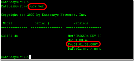
1. Find out what model of switch you are upgrading and what is current version of firmware running on the switch. Type "Show version" from the prompt.

- Model : C3G124-48
- Firmware : 01.01.02.0007

clip_image005
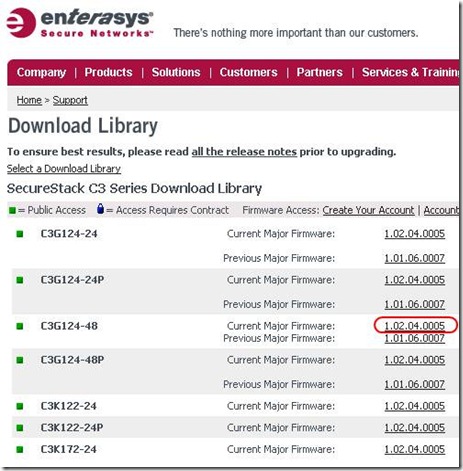
2. Go to the website "www.enterasys.com" and download proper firmware from the download library. and extract firmware to any folder your tftp server will use.

clip_image007

3. Assign IP address on the Enterasys switch in order to communicate with you computer which is running tftp server.
ex) computer 192.168.1.47, Enterasys switch is 192.168.1.8, default gateway .254

"set ip address 192.168.1.8 mask 255.255.255.0 gateway 192.168.1.254"


clip_image008
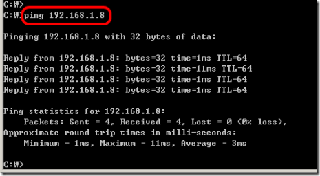
4. Ping the Enterasys switch from your computer.

clip_image009
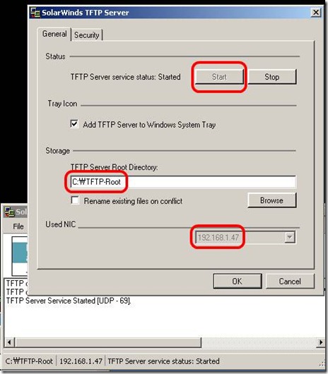
5. Execute tftp server. (If you don't have, just down one from solarwinds)

clip_image011
6. Copy firmware from tftp server

Enterasys(su)->copy tftp://192.168.1.47/c3-series_01.02.04.0005 system:image
- I will take time...to be done (few minutes)

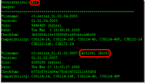
7. From the switch, make sure new firmware is uploaded and check which firmware version is on active.

clip_image012
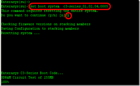
8. Type to "set boot system c3-series_01.02.04.0005" to booting up switch with new firmware(active).
B2(su)>>set boot system c3-series_01.02.04.0005
Do you want to replace ? (y/n) y
Automatically Enterasys switch will reboot.

clip_image013

9. Confirm now, new firmware is on active status.
The complete CLI reference manuals can be found at:
Enterasys C2 (Configuration Guide) :
http://www.penteknoloji.com.tr/destek/c2/1.pdf
Enterasys C3 (Configuration Guide): http://www.penteknoloji.com.tr/destek/c3/2.pdf

Saturday, December 24, 2011

Backup a Cisco Config Automatically – Time (Kron Method)

In order to get a router to copy the running-config to startup-config, for example every Sunday at 23:00, complete these steps:

1 - Create a kron policy list—This is the script that lists what commands the router should run at the scheduled time.

Router#enable
Router#configure terminal
Router(config)#kron policy-list Backup
Router(config-kron-policy)#cli show startup-config | redirect tftp://192.168.1.252/test.cfg
Router(config-kron-policy)#exit

cli—Specifies EXEC CLI commands within a Command Scheduler policy list.
policy-list—Specifies the policy list associated with a Command Scheduler occurrence.

Note: The reason why write was used rather than copy running-config startup-config is because kron does not support interactive prompts and the copy running-config startup-config command requires interaction. It is important to remember this when you create commands. Also, note that kron does not support configuration commands.


2 - Create a kron occurrence—This informs the router when and how often the policy should run.

Router(config)#kron occurrence SaveConfigSchedule at 23:00 Sun recurring
Router(config-kron-occurrence)#policy-list Backup

SaveConfigSchedule—This is the name of occurrence. Length of occurrence-name is from 1 to 31 characters. If the occurrence-name is new, an occurrence structure will be created. If the occurrence-name is not new, the existing occurrence will be edited.

at—Identifies that the occurrence is to run at a specified calendar date and time.
recurring—Identifies that the occurrence is to run on a recurring basis.


3 - Verify the kron configuration by using the show command.

Router#show kron schedule
Kron Occurrence Schedule
SaveConfigSchedule inactive, will run again in 1 days 12:37:47 at 23:00 on Sun

inactive—Means that kron is not running the command(s) at present.
active—Means that kron is running the current command(s).


Router#show running-configuration
...
kron occurrence SaveConfigSchedule at 23:00 Sun recurring
policy-list Backup
!
kron policy-list Backup
cli show startup-config | redirect tftp://192.168.1.252/test.cfg
...


Note: You can use this to schedule other things, just change the the policy-list, to what you want.

Based Onhttp://www.cisco.com/en/US/products/sw/iosswrel/ps1835/products_tech_note09186a008020260d.shtml