Showing posts with label remote. Show all posts

Sunday, November 1, 2015

Cisco - Port Mirror (SPAN / RSPAN / ERSPAN)

Introduction:

Switch port Analyzer (SPAN) is an efficient, high performance traffic monitoring system. It duplicated network traffic to one or more monitor interfaces as it transverse the switch. SPAN is used for troubleshooting connectivity issues and calculating network utilization and performance, among many others. There are three types of SPANs supported on Cisco products, which are illustrated in below diagram.

Types of SPAN:

SPAN1.jpgSPAN2.pngSPAN3.jpg

SPAN

SPAN1.jpg

Local SPAN: Mirrors traffic from one or more interface on the switch to one or more interfaces on the same switch.
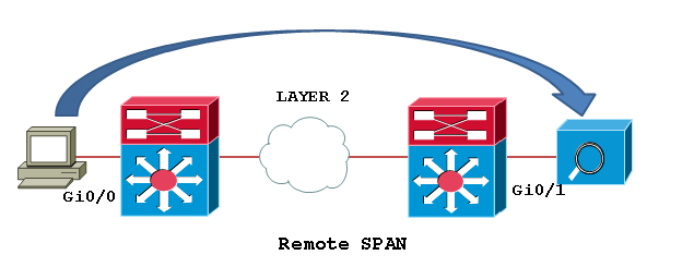
Remote SPAN (RSPAN): An extension of SPAN called remote SPAN or RSPAN. RSPAN allows you to monitor traffic from source ports distributed over multiple switches, which means that you can centralize your network capture devices. RSPAN works by mirroring the traffic from the source ports of an RSPAN session onto a VLAN that is dedicated for the RSPAN session. This VLAN is then trunked to other switches, allowing the RSPAN session traffic to be transported across multiple switches. On the switch that contains the destination port for the session, traffic from the RSPAN session VLAN is simply mirrored out the destination port.
Encapsulated remote SPAN (ERSPAN): encapsulated Remote SPAN (ERSPAN), as the name says, brings generic routing encapsulation (GRE) for all captured traffic and allows it to be extended across Layer 3 domains.

ERSPAN is a Cisco proprietary feature and is available only to Catalyst 6500, 7600, Nexus, and ASR 1000 platforms to date. The ASR 1000 supports ERSPAN source (monitoring) only on Fast Ethernet, Gigabit Ethernet, and port-channel interfaces.

Configuration Example:
Configuring Local SPAN: Local SPAN configures using “monitor session” command specifying source and destination on the same switch.

Switch1# configure terminal
Switch1(config)# monitor session 1 source interface fastEthernet0/2
Switch1(config)# monitor session 1 destination interface fastEthernet0/24
Switch1(config)#end

Local SPAN configuration syntax on Cisco IOS release 12.2(33)SXH and beyond as shown below.

monitor session 1 type local
source int fa0/2
destination int fa0/24


RSPAN

SPAN2.png

Step1: In order to configure RSPAN you need to have an RSPAN VLAN, those VLANs have special properties and can’t be assigned to any access ports. To create a VLAN for RSPAN on Cisco IOS, you must create the VLAN via the config-vlan configuration mode, as opposed to using the older VLAN database configuration mode. During the process of defining VLAN parameters, you must specify that the new VLAN is an RSPAN VLAN by configuring the remote-span VLAN configuration command.

Switch1# configure terminal
Switch1(config)# vlan 200
Switch1(config-vlan)# remote-span
Switch1(config-vlan)# end
Switch1# show vlan remote-span

Switch2# configure terminal
Switch2(config)# vlan 200
Switch2(config-vlan)# remote-span
Switch2(config-vlan)# end
Switch2# show vlan remote-span
Remote SPAN VLANs

Step2: Then configure the RSPAN on Source switch: Unlike SPAN, where the source and destination ports exist on the same switch, the source and destination ports for an RSPAN session reside on different switches. This requires a separate RSPAN source session to be configured, as well as a separate RSPAN destination session to be configured.

Switch1# configure terminal
Switch1(config)# monitor session 1 source interface fastEthernet0/2 rx
Switch1(config)# monitor session 1 destination remote vlan 200
reflector-port fastEthernet0/24
Switch1(config)# exit

Switch1# show monitor
Session 1
---------
Type                 : Remote Source Session
Source Ports     :
   Rx                 : Fa0/2
Reflector Port    : Fa0/24
Dest RSPAN VLAN  : 200

Step3: Configure the RSPAN on destination switch:
Switch2# configure terminal
Switch2(config)# monitor session 1 source remote vlan 200
Switch2(config)# monitor session 1 destination interface fastEthernet0/3
Switch2(config)# exit

The RSPAN VLAN should be allowed in ALL trunks between the involved switches (Source and Destination switches in this case); if you have enabled "pruning" in your network, remove the RSPAN VLAN from the pruning, with the command: “switchport trunk pruning vlan remove <RSPAN VLAN ID>” under the interface configure as trunk.

ERSPAN

SPAN3.jpg

In this example we will capture received traffic on the ASR 1002 (GigabitEthernet0/1/0) and send to Catalyst 6509 Gig2/2/1. This traffic will simply be captured, encapsulated in GRE by ASR 1002 natively by the QFP chipset and routed over to the Catalyst 6509. A sniffing station on the 6500 attached to GE2/2/1 will see the complete Ethernet frame (L2 to L7) information.
Configuring source interface, direction of traffic, and ERSPAN session ID on the ASR 1002.

ASR1002(config)# monitor session 1 type erspan-source
ASR1002(config-mon-erspan-src)# source interface gig0/1/0 rx
ASR1002(config-mon-erspan-src)# no shutdown
ASR1002(config-mon-erspan-src)# destination
ASR1002(config-mon-erspan-src-dst)# erspan-id 101
ASR1002(config-mon-erspan-src-dst)# ip address 10.1.1.1
ASR1002(config-mon-erspan-src-dst)# origin ip address 172.16.1.1

Configuring Catalyst 6509 to receive traffic from the source session on the ASR 1002

SW6509(config)# monitor session 2 type erspan-destination
SW6509(config-mon-erspan-dst)# destination interface gigabitEthernet2/2/1
SW6509(config-mon-erspan-dst)# no shutdown
SW6509(config-mon-erspan-dst)# source
SW6509(config-mon-erspan-dst-src)# erspan-id 101
SW6509(config-mon-erspan-dst-src)# ip address 10.1.1.1

You can use the show monitor session command to verify the configuration:

ASR1002#sh monitor session 1
Session 1
---------
Type                             : ERSPAN Source Session
Status                           : Admin Enabled
Source Ports                  :
RX Only                         : Gi0/1/0
Destination IP Address   : 10.1.1.1
MTU                              : 1464
Destination ERSPAN ID  : 101
Origin IP Address           : 172.16.1.1

To monitor the statistics of monitored traffic, you need to use "show platform hardware qfp active feature erspan state" command:

ASR1002#show platform hardware qfp active feature erspan state
ERSPAN State:
Status                : Active
Complexes         : 1
CPPs                 : 1
Capabilites          :
Max sessions      : 1024
Max outputs        : 128
Encaps type        : ERSPAN type-II
GRE protocol       : 0x88BE
MTU                    : 1464
IP TOS                : 0
IP TTL                 : 255
COS                   : 0
System Statistics:
DROP src session replica :                  0 /                 0
DROP term session replica:                 0 /                 0
DROP receive malformed   :                 0 /                 0
DROP receive invalid ID  :                    0 /                 0
DROP recycle queue full  :                   0 /                 0
DROP no GPM memory       :               0 /                 0
DROP no channel memory   :               0 /                 0
Client Debug Config:
Enabled: Info, Warn
Data Path Debug Config:
0x00000000
ASR1002#

Note:  10.1.1.1 is SW6509’s loopback. 172.16.1.1 Is ASR1002's loopback. ip address in destination session and ip address in source session should match. If they don't- that is causing the drops you see.

Taken From:

Sunday, August 30, 2015

Linux – SSH Reverse Tunnel to Bypass NAT

Have you ever wanted to reach a server via some application, for example ssh, but you couldn’t because the remote computer (LinuxB) was beind NAT, and you didn’t had access to the router (CPE2-NAT) to add a port forwarding:Top_Prob

but if you add another server with a Public IP (LinuxM) in the midlle you can set up a Reverse SSH Tunel between the destination (LinuxB) and the server in the middle (LinuxM) that will forward conection to a local port on LinuxM to the destination port  on LinuxB via the established ssh session that has the reverse/remote tunel configured.

Top_Solution

To test the Reverse SSH Tunel to bypass NAT I’m going to do a proof of concept (POC), with some linux (Ubuntu) machines with private addressing, the cenario looks like this:

Topologia_POC1


Linux_M – Middleman
===========================================================

## Hostname ##
sudo nano /etc/hostname
LinuxM
hostname LinuxM
hostname

sudo nano /etc/hosts
127.0.1.1       LinuxM


## Interfaces ##
sudo ifdown eth0                                                                 
sudo ifconfig eth0 192.168.1.254 netmask 255.255.255.0
sudo ifup eth0                                      

sudo ifdown eth1                                                                 
sudo ifconfig eth1 172.16.1.254 netmask 255.255.255.0
sudo ifup eth1


## IP Forwarding (Routing) ##
sudo  sysctl -w net.ipv4.ip_forward=1


## Activate Gateway Ports ##
sudo nano /etc/ssh/sshd_config
GatewayPorts yes
sudo service ssh stop
sudo service ssh start

#####################################################
# When you forward a TCP port (either locally or
# remotely), by default SSH only listens for
# connections to the forwarded port on the loopback
# address (localhost, 127.0.0.1). This means only
# other programs running on the same host as the
# listening side of the forwarding can connect to
# the forwarded port. This is a security feature,
# since there is no authentication applied to such
# connections. Also, such a forwarded connection is
# potentially insecure, since a portion of it is
# carried over the network in a plain TCP connection
# and not protected by SSH.
#####################################################


Linux_B – Destination
===========================================================

## Hostname ##
sudo nano /etc/hostname
LinuxB
hostname LinuxB
hostname

sudo nano /etc/hosts
127.0.1.1       LinuxB


## Interface ##
sudo ifdown eth0                                                                 
sudo ifconfig eth0 172.16.1.1 netmask 255.255.255.0
sudo ifup eth0


## Route (default) ##
sudo route add default gw 172.16.1.254 eth0


## Reverse/Remote SSH Tunnel ##
ssh -R 10002:localhost:22 lubuntu@172.16.1.254

######################################################
# This sets up the reverse/remote ssh tunnel
# between the destination (LinuxB) and the server
# in the middle (LinuxM) that will forward connection
# on the local port 10002 on LinuxM to the
# destination port 22 LinuxB via the established
# ssh session that has the reverse/remote tunel
# configured.
#
# After this command you will have the reverse/remote
# ssh thunnel configured and the bash/CLI of LinuxM.
#
# YOU MUST MAINTAIN THE BASH/CLI OF LinuxM ON LinuxB
# VIA SSH, FOR THE FORWARDING/TUNNELING TO WORK
#####################################################

At this point you have this:

Topologia_POC2

the reverse/remote ssh tunnel wating for a connection on LinuxM on port 10002 to forward LinuxB on port 22 (ssh)


Linux_A – Client
===========================================================

## Hostname ##
sudo nano /etc/hostname
LinuxA
hostname LinuxA
hostname

sudo nano /etc/hosts
127.0.1.1       LinuxA

 
## Interface ##
sudo ifdown eth0                                                                 
sudo ifconfig eth0 192.168.1.1 netmask 255.255.255.0
sudo ifup eth0


## Route (default) ##
sudo route add default gw 192.168.1.254 eth0   


## Connect LinuxM (will forward to LinuxB) ##
## Gateway Ports = ON on LinuxM                ##

ssh lubuntu@192.168.1.254 -p 10002

or

## Connect LinuxM (will not forward to LinuxB) ##
## Gateway Ports = OFF on LinuxM                      ##

ssh lubuntu@192.168.1.254         
ssh lubuntu@localhost -p 10002

######################################################
# Assuming the "Gateway Ports" is OFF, then the
# reverse/remote ssh tunnel will only be accessible
# on LinuxM locally
#
# So in the above commands we first connect via SSH
# to LinuxM, and from there connect local ports of the
# reverse/remote ssh tunnel so that it will forward
# the connection on the local port 10002 of LinuxM
# to the destination port 22 LinuxB
#####################################################

At this point you have this (Gateway Ports = ON):

Topologia_POC3 and you should be in the bash/CLI of LinuxB Sorriso


Related Links:


Friday, April 3, 2015

Arduino – EPLUG: Ethernet Controlled Power Plug

When I started  preparing for my CCNP SWITCH exam I bought some switches and set them up in my basement. After a couple of labs I realized I did a lot of trips to the basement to start / stop / restart the equipments. That’s when I started searching for remote controlled PDU, like this:

image

these are great but are very expensive for personal use (normally used in datacenters).

I already had an Arduino, so I started searching for a relay and cheap Ethernet NIC (the one on the arduino store was way to expensive), and I found the components below.

I put the components together and started programing the EPLUG program.

EPLUG is basically a small telnet Command Line Interface (CLI) that you can use to control multiple relays atached to Power Plugs. With this you can turn ON and OFF just about any electronic appliance you own from any device with telnet (PC, SmartPhone, Tablet, etc), using your Home Network or the Internet.
 
EPLUG was built as a framework that can be used for other projects. You can easily change the commands syntax by changing the text on the command patterns and add new commands by adding a new "else if(..){...}" statements on the "loop()" function.


Components

Relay Model: SRD-05VDC-SL-C

clip_image002

This relay board uses opto-couplers / opto-isolators to drive the relays, these isolate your Arduino from the relays, protecting it from voltage spikes. For more information check these videos:

Ethernet NIC Model: HR911105A

Shield Version

image

Breakout Board Version

ENC28J60_1

when i bought these components i did some basic tutorials on wich we are going to build upon, so you should check them out for more details or to test each component individually:


EPLUG Prototype

The complete build looks like this:

2015.04.04_Diagrama_Final

for the prototype I replaced the POWER CORD with an LED for testing:

image

my prototype looked like this:

image

The next step is to add the IP stack (uIP) for the Ethernet NIC (HR911105A).

You basically download the uIP IP stack here:

extract it, and put it on the arduino libraries folder

image


EPLUG as a Framework

The EPLUG program a simple and flexible Command Line Interface (CLI):

image

it receives the command on the function:

  • rcv_cmd(cmd, cmd_len)

 and matches them against the predefined patterns:

image

using the following functions:

  • cmd_equals (pattern,command) - exact match
  • cmd_startswith_l (pattern,command) - partial match, allow the commands to have a option (in this case the pin number)

and when it finds a match it executes an the function/actions for the corresponding command, as you can see below:

image

the structure above makes EPLUG very flexible, so that it’s easy to:

  • Change the current commands text
  • Add more commands (just add an else if (..){...} line)

my goal was to build EPLUG as a Framework for future projects.

For example if you want to do a program to set LEDs ON/OFF LEDs, you just need to change the patterns and the action functions and in 10 minutes or less your program is done.


Available Pins for Relays

There are some pins that that you should not use:

image

so you should only use the following pins:

  • Pin 2
  • Pin 3
  • Pin 4
  • Pin 5
  • Pin 6
  • Pin 7
  • Pin 8 I used this PIN
  • Pin 9

you can basically plug up to 8 relays to an Arduino UNO and controll them with the EPLUG program.


Loading EPLUG

Get the EPLUG code here:

Open the EPLUG code on the Arduino IDE:

image

To upload the program to Arduino just press:

image

after compiling and uploading the IDE show the program size, and it should be 25.xxx bytes.

Problem: I found out that, for some reason, if the program is a bit over 26.000 bytes the Ethernet NIC doesn’t work properly. The maximum on the Arduino UNO is 32.256 bytes so this shouldn`t happen.


Testing EPLUG

First you need to find the IP of the Arduino NIC and make sure it’s on the correct network (your LAN network), you can do that here:

image

now telnet to it:

image

press ENTER to start the CLI and show the options:

image

to set the “relay” (for now the LED) on you type:

image

you should get something like this:

Prototype1

Problem: After some time (1-3 min) the LED goes off for no aparent reason. After some research I found that this behavior is the the Arduino’s In System Programer (ISP) checking  if you want to reprogram Arduino from your PC (basically resets Arduino). The solution is very simple, you just don’t power the Arduino from your PC, you use a power supply.

to show the “relay” (LED) current state, you type:

image

to show all the “relays” (LEDs) current state, you type:

image

to set off the “relay” (LED), you type:

image

to show info about EPLUG, you type:

image

to close the telnet session, you type:

image


Putting It All Together

Now we can replace the LED with the POWER CORD, and use/test EPLUG in the real world.

2015.04.04_Diagrama_Final

In this diagram the POWER CORD starts OFF, if you want it to start ON just change the wire on the relay from NO (normally open) to NC (normally closed).

My build looked like this:

REAL1

image

image

now you can test/use it in the real world, check out my test video:

EPLUG Test

Next Steps

  • Add an internal USB power supply
  • Make it a lot smaller/cheaper (microntroller + breakout board)
  • Make a version with GSM aka GPLUG (SMS or GPRS)
  • Make a version with Radio modules aka RPLUG
  • Map relays to numbers different from the PINs
  • Save the pins state to a non-volatile memory (EEPROM)
  • Add a current sensor

Check out my makers community at:

Saturday, November 8, 2014

Wake on Lan - Linux

HowTo: Wake Up Computers Using Linux Command [ Wake-on-LAN ( WOL ) ] by NIXCRAFT on APRIL 3, 2012

Wake-on-LAN (WOL) is an Ethernet networking standard that allows a server to be turned on by a network message. You need to send 'magic packets' to wake-on-lan enabled ethernet adapters and motherboards, in order to switch on the called systems. Make sure you connect the NIC (eth0 or eth1) with the motherboard, and enable the WOL function in the BIOS. This is a quick guide to enable WOL under RHEL / Fedora / CentOS / Debian / Ubuntu Linux.

Client Software

You need to use software to send WoL magic packets. You will find various tools for all modern oses, including MS-Windows, Apple OS X, Linux, and many smart phones.
Linux Install etherwake Under Debian / Ubuntu Linux
etherwake command can be used to send a Wake-On-LAN "Magic Packet" under Linux operating systems. Type the following command to install the same under Debian / Ubuntu Linux desktop:

$ sudo apt-get install etherwake

[sudo] password for vivek:
The following NEW packages will be installed:
  etherwake wakeonlan{a}
0 packages upgraded, 2 newly installed, 0 to remove and 11 not upgraded.
Need to get 20.9 kB of archives. After unpacking 98.3 kB will be used.
Do you want to continue? [Y/n/?] y
Get:1
http://mirror.anl.gov/debian/ squeeze/main etherwake amd64 1.09-3 [9,564 B]
Get:2
http://mirror.anl.gov/debian/ squeeze/main wakeonlan all 0.41-10 [11.4 kB]
Fetched 20.9 kB in 2s (10.3 kB/s)
Selecting previously deselected package etherwake.
(Reading database ... 195338 files and directories currently installed.)
Unpacking etherwake (from .../etherwake_1.09-3_amd64.deb) ...
Selecting previously deselected package wakeonlan.
Unpacking wakeonlan (from .../wakeonlan_0.41-10_all.deb) ...
Processing triggers for man-db ...
Setting up etherwake (1.09-3) ...
Setting up wakeonlan (0.41-10) ...

Note: Red Hat Linux and friends user should use net-tools package which is installed by default.

How Do I Send WOL Magic Packets Under Linux?

Type the following command:
# wakeonlan MAC-Address-Here
OR
# etherwake MAC-Address-Here
# etherwake -D MAC-Address-Here

RHEL / Centos / Fedora Linux user, try:
# ether-wake MAC-Address-Here
If your MAC address were xx:yy:zz:11:22:33, you would type:
# wakeonlan xx:yy:zz:11:22:33
OR
# etherwake xx:yy:zz:11:22:33

Where, xx:yy:zz:11:22:33 is remote servers mac address. You can obtained mac address using combination of ping and arp command - 'ping -c 4 server3 && arp -n'.

How Do I Verify That Remote Linux Server Supports Wake-on-LAN (WOL)?

First, reboot the remote server and go to BIOS > Power Management > "Wake On LAN". Turn it on. Next, save and close the bios. After activating Wake On LAN in hardware (BIOS) it is also necessary to activate it using ethtool. The ethtool will configure eth0 to respond to the magic packet:

# ethtool -s eth0 wol g

Where,
1. -s eth0: Your NIC. Feel free to replace eth0 with your actual network interface device name.
2. wol g: Sets Wake-on-LAN options using MagicPacket.

Type the following command to see current status of wol for eth0:
# ethtool eth0
Settings for eth0:
    Supported ports: [ ]
    Supported link modes:
    Supports auto-negotiation: No
    Advertised link modes:  Not reported
    Advertised auto-negotiation: No
    Speed: 100Mb/s
    Duplex: Full
    Port: MII
    PHYAD: 1
    Transceiver: internal
    Auto-negotiation: off
        Supports Wake-on: g
       Wake-on: g

    Link detected: yes


If you are using RHEL / SL / Fedora / CentOS Linux, edit /etc/sysconfig/network-scripts/ifcfg-eth0:

# vi /etc/sysconfig/network-scripts/ifcfg-eth0
Add / modify the following line:
 
ETHTOOL_OPTS="wol g"

OR
ETHTOOL_OPTS="wol g autoneg off speed 100 duplex full "

 
Save and close the file. If you are using Debian / Ubuntu Linux, edit /etc/network/interfaces:

# vi /etc/network/interfaces
Append the following to eth0:

auto eth0
iface eth0 inet static
address 192.168.1.1
netmask 255.255.255.0
gateway 192.168.1.254
        post-up /sbin/ethtool -s eth0 wol g
        post-down /sbin/ethtool -s eth0 wol g
 

post-up and post-down execute a comand or a script when the interface comes up and when it goes down. Here we used it for  ethtool, but you can use it for anything you want.


Recommend readings
- man pages - ethtool, ether-wake / etherwake, arp, wakeonlan
- Wake-on-LAN

Taken From: http://www.cyberciti.biz/tips/linux-send-wake-on-lan-wol-magic-packets.html

Thursday, August 23, 2012

Stream Videos and Music Over the Network With VLC

clip_image002

VLC includes a fairly easy-to-use streaming feature that can stream music and videos over a local network or the Internet. You can tune into the stream using VLC or other media players.

Use VLC’s web interface as a remote control to control the stream from elsewhere. Bear in mind that you may not have the bandwidth to stream high-definition videos over the Internet, though.

Broadcasting a Stream

To start broadcasting a network stream, click the Media menu in VLC and select Stream.

clip_image004

In the Open Media dialog, select the media you want to stream. You can select one or more files on the Files tab, select a CD or DVD on the Disc tab, or even capture video from a specific device on the Capture Device tab. For example, you could stream your desktop by selecting Desktop on the Capture Device tab.

Click the Stream button after selecting your media.

clip_image006

The Stream Output window will appear. The first pane just lists the media source you selected – click Next to continue.

clip_image008

On the Destination Setup pane, you’ll need to choose a destination for your stream. For example, you can select HTTP to listen for connections – other computers can connect to your computer and watch the stream. You can also select UDP to broadcast to a specific IP address or range of IP addresses.

After selecting your destination, click the Add button. You may also want to activate the Display locally check box – if you do, you’ll see and hear the media being streamed on your local computer, so you’ll know it’s playing correctly.

clip_image010

After adding a destination, you’ll be able to customize its settings. With the HTTP destination, you could specify a custom path – but the default one will work fine.

You can also tweak the transcoding settings – by transcoding to a lower quality, VLC can save network bandwidth.

clip_image012

Click Next to continue to the Option Setup pane – you probably don’t need to tweak any of the advanced options here. To start streaming, click the Stream button.

clip_image014

If you selected the Display locally option, the media will start playing locally on your computer.

If you have a firewall enabled, ensure that VLC is an allowed program or no computers will be able to connect. If you’re trying to stream over the Internet, you may also need toforward ports on your router.

Connecting to a Stream

To tune in to a stream, click the Media menu in VLC on another computer and select Open Network Stream.

clip_image016

Assuming you used HTTP, enter an address like http://IP.Address:8080. See this postif you need help finding the other system’s IP address.

(If you specified a custom path for your HTTP stream in the Path box, you’ll need to specify the custom path here. For example, if you specified /path as your custom path, you’d enter http://IP.Address:8080/path in the box here.)

clip_image018

After clicking Play, the stream should start playing. To control playback remotely, trysetting up VLC’s web interface. If you encounter an error, make sure VLC isn’t being blocked by a firewall on the streaming system.

clip_image020

Taken From: http://www.howtogeek.com/118075/how-to-stream-videos-and-music-over-the-network-using-vlc/