Showing posts with label switch. Show all posts

Tuesday, January 3, 2017

Finding Your Public IP with Telnet (CLI)

Her I’m going to show you a little trick off a way to get you public IP when you just have a command line interface.

This can be done in any equipment with telnet like a:

  • Router
  • Switch
  • Linux Server
  • etc


How To Do It – Site: Check IP

The webpage:

gives out you public IP on a Browser, so what we are going to do is to open the Web Page on the HTTP Port (Port 80), and get a response from the webpage with you Public IP.

This Web Page does not need you to send HTML to pretend that your telnet is a Web Browser (like the IP Echo Website bellow)

To do it:

telnet checkip.dyndns.org 80

or

telnet 216.146.38.70 80

if you don’t have DNS configured, and then do as soon as it connects press:

  • ENTER (one or two times)

and it will give you the output bellow.

image


How To Do It – Site: IP Echo 

The webpage:

gives out you public IP on a Browser, so what we are going to do is to open the Web Page on the HTTP Port (Port 80), and then send some HTML code to pretend that your telnet is a Web Browser to get the HTML response from the webpage with you Public IP.

To do it:

telnet ipecho.net 80

or

telnet 146.255.36.1 80

if you don’t have DNS configured, and then paste the following HTML code

GET / HTTP/1.1
Host: ipecho.net
User-Agent: Mozilla/4.0 (compatible; MSIE 7.0; Windows NT 5.1)

and press Enter, and you get this:

01

rigth here you can see you IP.


See Public IP on a Browser

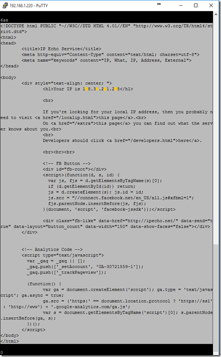
In both methods/sites if you want, you can see the IP in a more pretty way, just copy the HTML code the Web Page returned (this output is from the IP Echo site):

02

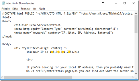
to a text file with the “.html” extension in the computer you are using, I named mine index.html

03

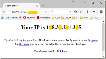
save it and double click in the index.html which will open on your default browser, and show the HTML you copied from the command line:

04

Sunday, September 18, 2016

Cisco - Upgrade Switches From Tar (Bin+Html)

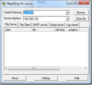
To upgrade a Cisco Switch from a .tar (IOS and Html - Management Web Page), just start TFTP64:

image

and use the command:

  • archive download-sw xxxxxxxxxx

on the switch command line, this will download and install the .tar, and set it to boot next time.

I normally use is the my “Main Command” this should work in most cases, but you have other options like the ones shown in “Command Options”, that you can use “as is”, or by combining them like the “Main Command”.


Main Command

Download & Install - Overwrite & Different Feauture Set
============================================
Download from TFTP server and unpack tar
and install it (IOS and Html - Management Web Page)
even if the current and the new image have diferent
feature sets (ex: ipbase vs ipservices)

archive download-sw /overwrite /allow-feature-upgrade tftp://192.168.1.230/c3560-ipservicesk9-tar.150-2.SE.tar

OPTIONS USED
/allow-feature-upgrade - update/downgrade to
                                    different feature set
                         
/overwrite                   - overwrite everything in
                                    the flash with the new
                                    IOS tar image


Command Options

Download & Install
============================================
Download from TFTP server and unpack tar and
install it (IOS and Html - Management Web Page)

archive download-sw tftp://192.168.1.230/c3560-ipservicesk9-tar.150-2.SE.tar


Download & Install - Overwrite
============================================
Download from TFTP server and unpack tar and
install it (IOS and Html - Management Web Page)
and overwrite everything in the flash with the
new downloaded IOS tar image

archive download-sw /overwrite tftp://192.168.1.230/c3560-ipservicesk9-tar.150-2.SE.tar

 OPTIONS USED
/overwrite - overwrite everything in the flash
                    with the new IOS tar image

 
Download & Install - Different Feauture Set
============================================
Download from TFTP server and unpack tar
and install it (IOS and Html - Management Web Page)
even if the current and the new image have diferent
feature sets (ex: ipbase vs ipservices)

archive download-sw /allow-feature-upgrade tftp://192.168.1.230/c3560-ipservicesk9-tar.150-2.SE.tar

OPTIONS USED
/allow-feature-upgrade - update/downgrade to different feature set


Download & Install - Image Only
============================================
Download from TFTP server and unpack tar
and install it only the IOS (.bin) and deletes
the Html files (Management Web Page)

archive download-sw /imageonly  tftp://192.168.1.230/c3560-ipservicesk9-tar.150-2.SE.tar

 OPTIONS USED
 /imageonly - Install only the IOS (.bin) image and
                      delete the Html files (Management Web Page)
 
 
Download & Install - Safe
============================================
Download from TFTP server and unpack tar
and install it (IOS and Html - Management Web Page).

Waits for new IOS to be downloaded successfully
before deleting the old IOS

archive download-sw /safe tftp://192.168.1.230/c3560-ipservicesk9-tar.150-2.SE.tar

OPTIONS USED
/safe - waits for the new IOS to be downloaded
           successfully before deleting the old IOS
        

Base On: https://cyruslab.net/2012/06/03/maintenance-ios-upgradedowngrade-with-archive-download-sw-command/

Thursday, August 20, 2015

Cisco - Router / Switch as an HTTP Server

You can use your Cisco router / switch as a Web server, Cisco IOS routers have HTTP interface since IOS 11.2, in IOS 12.2(15)T it was enhanced with HTTP 1.1 Web server that offers Secure Socket Layer (SSL) Version 3.

Let’s test it out, I actually did this on a switch (cisco 3560)


First let’s check current root folder for the HTTP server, in order to get a reference to restore the HTTP root path later:

DSw1#show ip http server status
HTTP server status: Enabled
HTTP server port: 80
HTTP server authentication method: enable
HTTP server access class: 0
HTTP server base path: flash:/c3560-ipservicesk9-mz.150-1.SE/html
HTTP server help root:
Maximum number of concurrent server connections allowed: 16
Server idle time-out: 180 seconds
Server life time-out: 180 seconds
Maximum number of requests allowed on a connection: 25
HTTP server active session modules: ALL
HTTP secure server capability: Present
HTTP secure server status: Enabled
HTTP secure server port: 443
HTTP secure server ciphersuite: 3des-ede-cbc-sha des-cbc-sha rc4-128-md5 rc4-128-sha
HTTP secure server client authentication: Disabled
HTTP secure server trustpoint:
HTTP secure server active session modules: ALL

To transfer the web page we are going to use TFTP, for the server just run TFPT32 / TFTP64 in your computer, and point it to the folder where you have the web page you want to transfer to your router / switch.

1

On router / switch copy the web page from the TFTP server (your PC) to your router / switch:

DSw1#copy tftp://192.168.1.52/index.html flash://index.html
Destination filename [index.html]?
Accessing tftp://192.168.1.52/index.html...
Loading index.html from 192.168.1.52 (via Vlan99): !
[OK - 15772 bytes]

 
DSw1#show flash
Directory of flash:/
     2  -rwx       15772   Mar 1 1993 00:26:36 +00:00  index.html
      3  -rwx          1276   Mar 1 1993 00:00:40 +00:00  vlan.dat
  363  drwx         256   Mar 1 1993 00:39:23 +00:00  c3560-ipservicesk9-mz.150-1.SE
  487  -rwx        4189   Mar 1 1993 00:19:41 +00:00  config.text

Now in the golbal configuration mode lets enable the HTTP server, set the path to root folder of the HTTP server, and activate local authentication, and a local user and password (if you don’t already don’t have one)

ip http server
ip http path flash://
ip http authentication local

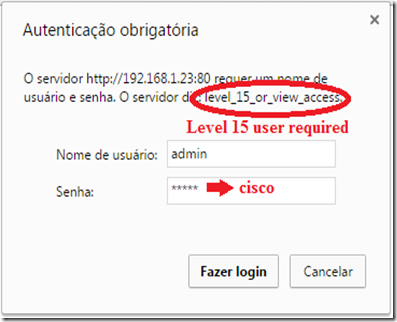
username admin privilege 15 password 0 cisco  (the user level must be 15)

you can also have HTTPS (secure) server using by adding the following command:

ip http secure-server

Here's a list of important commands you should know. These commands are in global configuration mode and have the format “ip http xxxxx”.

  • access-class: This restricts access to your Web server using an access list.
  • authentication: This sets the authentication for login to the Web server to either local, enable, or tacacs.
  • path: This establishes the root path where the Web server begins looking for files.
  • port: This allows you to change the port number for the Web server from 80 to another port.
  • server: This enables and disables the Web server.
  • secure-server: This enables and disables the SSL Web server.
          

Let’s check the new root folder for the HTTP server:
   
DSw1#show ip http server status
HTTP server status: Enabled
HTTP server port: 80
HTTP server authentication method: local
HTTP server access class: 0
HTTP server base path: flash:/
HTTP server help root:
Maximum number of concurrent server connections allowed: 16
Server idle time-out: 180 seconds
Server life time-out: 180 seconds
Maximum number of requests allowed on a connection: 25
HTTP server active session modules: ALL
HTTP secure server capability: Present
HTTP secure server status: Enabled
HTTP secure server port: 443
HTTP secure server ciphersuite: 3des-ede-cbc-sha des-cbc-sha rc4-128-md5 rc4-128-sha
HTTP secure server client authentication: Disabled
HTTP secure server trustpoint:
HTTP secure server active session modules: ALL


Now open your browser, and type:

http://<your_router_or_switch_ip_address>

03

you will be prompted for a local user and password, and you should get you web page shown:
    02

Based On: http://www.techrepublic.com/article/take-advantage-of-the-cisco-ios-web-server-on-your-router/

Saturday, June 6, 2015

Huawei - Switch: Basic QinQ Tunnel (aka 802.1Q Tunneling)

How to Configure Basic QinQ?

Posted on December 8, 2014


Networking Requirements

As shown in the below figure, there are two enterprises on the network, Enterprise 1 and Enterprise 2. Enterprise 1 has two office locations, and Enterprise 2 has 2 office locations. The office locations of the two enterprises access SwitchA and SwitchB of the ISP network. A non-Huawei device with the TPID value 0x9100 exists on the public network.

The requirements are as follows:

  • Enterprise 1 and Enterprise 2 plans their VLANs independently.
  • Traffic of the two branches is transparently transmitted on the public network. Users using the same services in the two branches are allowed to communicate and users using different services are isolated.

You can configure QinQ to meet the preceding requirements. VLAN 100 provided by the public network can be used to implement communication of Enterprise 1 in the two branches and VLAN 200 is used for Enterprise 2. You can set the TPID value in the outer VLAN on the interface that connects the non-Huawei device to implement communication between devices.

Note: This example can be applied to Huawei switches higher level than Quidway S2700 and with EI version.


Configuring basic QinQ

configuring-basic-qinq


Configuration Roadmap

The configuration roadmap is as follows:

  • Configure VLAN 100 and VLAN 200 on both SwitchA and SwitchB. Set the link type of the interface to QinQ and add the interfaces to VLAN. In this way, different outer VLAN tags are added to different services.
  • Add interfaces connecting to the public network on SwitchA and SwitchB to VLAN 100 and VLAN 200 to permit packets from these VLANs to pass through.
  • Set the TPID values in the outer VLAN tag on interfaces connecting to the public network on SwitchA and SwitchB to implement communication between the device with devices from other vendors.

Procedure


Create VLANs.

# Create VLAN 100 and VLAN 200 on SwitchA.
<HUAWEI> system-view
[HUAWEI] sysname SwitchA
[SwitchA] vlan batch 100 200

# Create VLAN 100 and VLAN 200 on SwitchB.
<HUAWEI> system-view
[HUAWEI] sysname SwitchB
[SwitchB] vlan batch 100 200


Set the link type of the interface to QinQ.

# Configure GE0/0/1 and GE0/0/2 of SwitchA as QinQ interfaces. Set the VLAN of GE0/0/1 to VLAN 100 and the VLAN of GE0/0/2 to VLAN 200. The configuration of SwitchB is similar to the configuration of SwitchA, and the configuration details are not mentioned here.
[SwitchA] interface gigabitethernet 0/0/1
[SwitchA-GigabitEthernet0/0/1] port link-type dot1q-tunnel
[SwitchA-GigabitEthernet0/0/1] port default vlan 100
[SwitchA-GigabitEthernet0/0/1] quit

[SwitchA] interface gigabitethernet 0/0/2
[SwitchA-GigabitEthernet0/0/2] port link-type dot1q-tunnel
[SwitchA-GigabitEthernet0/0/2] port default vlan 200
[SwitchA-GigabitEthernet0/0/2] quit

Configure the interface connecting to the public network on the switch.

# Add GE0/0/3 of SwitchA to VLAN 100 and VLAN 200. The configuration of SwitchB is similar to the configuration of SwitchA, and the configuration details are not mentioned here.
[SwitchA] interface gigabitethernet 0/0/3
[SwitchA-GigabitEthernet0/0/3] port link-type trunk
[SwitchA-GigabitEthernet0/0/3] port trunk allow-pass vlan 100 200
[SwitchA-GigabitEthernet0/0/3] quit

Configure the TPID value for an outer VLAN tag

# Set the TPID value of an outer VLAN tag to 0x9100 on SwitchA.
[SwitchA] interface gigabitethernet 0/0/3
[SwitchA-GigabitEthernet0/0/3] qinq protocol 9100

# Set the TPID value of an outer VLAN tag to 0x9100 on SwitchB.
[SwitchB] interface gigabitethernet 0/0/3
[SwitchB-GigabitEthernet0/0/3] qinq protocol 9100

Verify the configuration.

In Enterprise 1, ping a PC of a VLAN in a branch from a PC of the same VLAN in another branch. If the two PCs can ping each other, internal users of Enterprise 1 can communicate.

In Enterprise 2, ping a PC of a VLAN in a branch from a PC of the same VLAN in another branch. If the two PCs can ping each other, internal users of Enterprise 2 can communicate.

Ping a PC in a VLAN of Enterprise 2 in a branch from a PC in the same VLAN of Enterprise 1 in either branch. If the two PCs cannot ping each other, users in Enterprise 1 and Enterprise 2 are isolated.


Configuration Files

# Configuration file of SwitchA
sysname SwitchA
#
vlan batch 100 200
#
interface GigabitEthernet0/0/1
port link-type dot1q-tunnel
port default vlan 100
#
interface GigabitEthernet0/0/2
port link-type dot1q-tunnel
port default vlan 200
#
interface GigabitEthernet0/0/3
qinq protocol 9100
port link-type trunk
port trunk allow-pass vlan 100 200
#
return


#Configuration file of SwitchB
sysname SwitchB
#
vlan batch 100 200
#
interface GigabitEthernet0/0/1
port link-type dot1q-tunnel
port default vlan 100
#
interface GigabitEthernet0/0/2
port link-type dot1q-tunnel
port default vlan 200
#
interface GigabitEthernet0/0/3
qinq protocol 9100
port link-type trunk
port trunk allow-pass vlan 100 200
#
return

The more information about technical support you can consult with our engineer – Bill, and his e-mail address is as below:

bill@huanetwork.com

Taken From: http://www.huanetwork.com/blog/how-to-configure-basic-qinq/

Sunday, August 3, 2014

Spanning Tree – PVST / PVST+/ MST – Bridge ID and Root Selection

Spanning Tree Protocol: Bridge ID, Priority, System ID Extension & Root Bridge Election Process

Written by Arani Mukherjee. Posted in Spanning Tree Protocol (STP)

In this article we will examine the Spanning Tree Bridge ID structure, explain why it has increments of 4096, how VLAN information is embedded (for Per-VLAN Spanning Tree & multiple STP instances) via the System ID Extension and finally explain how the Spanning Tree Protocol Root Bridge Election occurs.

Understanding Bridge ID, Bridge Priority & System ID Extension

In our earlier article we discussed about the Spanning Tree Protocol, Rapid STP port costs and port states. Before STP decides which path is the best to the Root Bridge, it needs to first decide which switch has to be elected as the Root Bridge, which is where the Bridge ID comes into play. Readers interested can also read our STP Principles, Redundant Network Links & Broadcast Storms article.

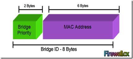
Every switch has an identity when they are part of a network. This identity is called the Bridge ID or BID. It is an 8 byte field which is divided into two parts. The first part is a 2-byte Bridge Priority field (which can be configured) while the second part is the 6-byte MAC address of the switch. While the Bridge Priority is configurable, the MAC address is unique amongst all switches and the sum of these two ensures a unique Bridge ID.

clip_image001

The above Bridge ID assumes there is one Spanning Tree instance for the entire network. This is also called Common Spanning-Tree (CST).

As networks begun to grow and become more complex, VLANs were introduced, allowing the creation of multiple logical and physical networks. It was then necessary to run multiple instances of STP in order to accommodate each network - VLAN. These multiple instances are called Multiple Spanning Tree (MST), Per-VLAN Spanning Tree (PVST) and Per-VLAN Spanning Tree Plus (PVST+).

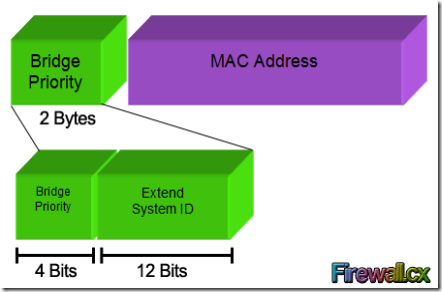
In order to accommodate the additional VLAN information, the Extended System ID field was introduced, borrowing 12 bits from the original Bridge Priority:

clip_image002

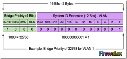
The Bridge Priority value and the Extended System ID extension together make up a 16 bit (2-byte) value. The Bridge Priority making up the left most bits, is a value of 0 to 61440. The Extended System ID is a value of 1 to 4095 corresponding to the respective VLAN participating in STP. The Bridge Priority increments in blocks of 4096 to allow the System ID Extension to squeeze in between each increment. This is clearly shown in the below analysis:clip_image003 We should note that the Bridge Priority Field can only be set in increments of 4096. This means that possible values are: 4096, 8192, 12288, 16384, 20480, 24576, 28672, 32768 etc. By default, Cisco’s Per-VLAN Spanning-Tree Plus (PVST+) adds this System ID Extension (sys-id-ext) to the Bridge Priority.

The two values (Bridge Priority + System ID Extension) together make up the Bridge ID used to elect the Root Bridge.

The Root Bridge Election Process

The election process uses several STP messages sent between switches which help each switch to decide, who is the Root Bridge. These messages are called Hello BPDU where BPDU stands for Bridge Protocol Data Unit. It is important to understand the information these BPDUs carry as it will help understand the election process itself.

Each BPDU carries several fields in it. The following table defines each field:

Field

Description

Root Bridge ID or Root BID

BID of the switch that the sender of this BPDU believes to be the root switch

Sender’s Bridge ID

BID of the switch sending this Hello BPDU

Cost to the Root Bridge

The STP cost between this switch and the current root

Timer values on Root Bridge

Hello Timer, Max Age Timer, Forward Delay Timer

For the purpose of this exercise, we will only concentrate on the first three fields.

Now, the election process itself is very simple. The switch with the lowest BID becomes the Root Bridge. Since the BID starts with the Bridge Priority field, essentially, the switch with the lowest Bridge Priority field becomes the Root Bridge. If there is a tie between two switches having the same priority value, then the switch with the lowest MAC address becomes the Root Bridge.

The STP Root Bridge election process starts with each switch advertising themselves as the Root Bridge and constructing the Hello BPDU accordingly. So each switch lists its own BID as the Root BID. The Sender Bridge ID is ofcourse the same as the Root BID, as it is again its own BID. With in BPDU, the Cost field is listed with a value of 0, because there is no cost between itself. The switches send out the Hello BPDU constructed as above, onto the network. They will keep on maintaining their status as Root Bridge by default, until they receive a Hello BPDU which carries a lower BID. This Hello BPDU then becomes a superior BPDU. Now the switch receiving this superior BPDU makes changes to the Hello BPDU it has been sending out. It changes the value of the Root BID to reflect the Root BID from the superior Hello BPDU. This process continues till every switch agrees on which switch has the lower BID, and hence deserves to be the Root Bridge.

Root Bridge Election Example

Let's look at this process using a three switch combination within a network. For the sake of simplicity, the MAC address of each switch has been changed to a simple value:

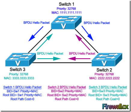
clip_image004

· Switch 1 (SW1). Has a priority of 32768 and MAC address of 1111.1111.1111. So its BID becomes 32768.1111.1111.1111. When SW1 creates its own BPDU, it sets both BID and Root BID to 32768.1111.1111.1111.

· Switch 2 (SW2). Has a priority of 32768 and MAC address of 2222.2222.2222. So its BID becomes 32768.2222.2222.2222. When SW2 creates its own BPDU, it sets both BID and Root BID to 32768.2222.2222.2222.

· Switch 3 (SW3). Has a priority of 32768 and MAC address of 3333.3333.3333. So its BID becomes 32768.3333.3333.3333. When SW3 creates its own BPDU, it sets both BID and Root BID to 32768.3333.3333.3333.

Now, the election process commences with the advertisement of the individual Hello BPDU's from each switch, as indicated by the arrows in our diagram. These BPDUs originate from each switch and end up at the other switches. Let's take up one switch at a time to see how it reacts to the BPDUs it receives from the other switches.

Switch 1 (SW1): It had sent out its own Hello BPDU with both BID and Root BID set to 32768.1111.1111.1111. When it receives the Hello BPDU from SW2, it checks for the Root BID value which is 32768.2222.2222.2222. SW1 discards the BPDU sent by SW2, as it still is the switch with the lowest BID. Same situation happens when it receives the Hello BPDU from SW3. SW1 is still the switch with the lowest BID. So it discards the Hello BPDU received from SW3 and keeps on advertising itself as the Root Bridge.

Switch 2 (SW2): Just like SW1, SW2 generates and sends its own Hello BPDU with both BID and Root BID set to 32768.2222.2222.2222. When it receives the Hello BPDU from SW1, it checks for the Root BID value which SW1 has set to 32768.1111.1111.1111. This being lower than SW2's own BID, makes the Hello BPDU received from SW1, a superior BPDU. So in its own BPDU, SW2 changes the value of the Root BID from 32768.2222.2222.2222, to 32768.1111.1111.1111, and starts advertising this revised Hello BPDU. SW2 now considers SW1 as the Root Bridge. Now, when it receives the Hello BPDU from SW3, it will obviously discard the BPDU as it is not superior in Root BID value. So for SW2, SW1 remains as Root Bridge, even after receiving the Hello BPDU from SW3.

Switch 3 (SW3): SW3 will send out its own Hello BPDU with both BID and Root BID set to 32768.3333.3333.3333. Depending on which Hello BPDU it receives first i.e. from SW1 or SW2, it will end up changing the Root BID value in its Hello BPDU because both SW1 & SW2 have lower MAC addresses. So if it received the Hello BPDU from SW2 first, then it will change the Root BID from 32768.3333.3333.3333 to 32768.2222.2222.2222 and consider SW2 as new Root Bridge. Once it receives the Hello BPDU from SW1, this BPDU supersedes the BPDU sent by SW2. So SW3 changes the Root BID from 32768.2222.2222.2222 to 32768.1111.1111.1111 and now considers SW1 as new Root Bridge.

At this point, all switches have received each other's BPDU and have agreed that SW1 has the lowerst BID address and is therefore the rightful Root Bridge of the network. Both SW2, and SW3 now agree that SW1 is Root Bridge, and start organizing their respective links into Root Ports and Designated Ports.

What if we wanted Switch 3 to be the Root Bridge?

In most real-life cases, we need to configure the Root Bridge to ensure that no matter the switch that joins the network, our initial Root Bridge will remain. To achieve this, we simply configure the Bridge Priority so that it is always smaller than the default value of 32768.

In our example, if we wanted Switch 3 to become the new Root Bridge, we would set its Bridge Priority to 4096. By doing so, we change its BID to 4096.3333.3333.3333 making it the lowest amongst our network switches.

Configuring a new BID in a production network is not recommended unless every caution has been taken to ensure network downtime is eliminated. When the BID of a switch changes to make it a Root Bridge, the whole network (switches) will react upon this and begin recomputing the new information. Depending on where the new Root Bridge is located, switch uplinks and redundant links might be blocked.

This article analysed the Spanning Tree Protocol Bridge ID structure and its importance. We saw how the Bridge Priority and System ID Extension fields play a primary role in the Root Bridge election within a network.

Taken From: http://www.firewall.cx/networking-topics/protocols/spanning-tree-protocol/1054-spanning-tree-protocol-root-bridge-election.html

Spanning Tree – STP / RSTP - Port Costs and States

Spanning Tree Protocol, Rapid STP Port Costs - Port States

Written by Arani Mukherjee. Posted in Spanning Tree Protocol (STP)

Spanning Tree Protocol, Rapid STP port costs and port states are an essential part of the STP algorithm that affect how STP decides to forward or block a port leading to the Root Bridge.

In our previous article that covers Understand STP Principles, Redundant Network Links & Broadcast Storms we encountered some key issues related to switching that causes degradation in network performance.

Those issues were broadly categorised as follows:

· Broadcast storm

· Unstable MAC Table in switches

· Multiple duplicate frames arriving at hosts

In order to avoid the above situations, Spanning Tree Protocol or STP is implemented. The aim of this protocol and its deployment is to provide a single path of communication between each Ethernet segment (e.g a link between two switches). Since the issues discussed in our previous article, and STP itself only relates to switching, our discussion will only refer to switches. It is worth noting that both bridges and switches make use of the STP protocol.

To create a single path between each Ethernet segment, for to and fro communication, STP decides on the state of each Ethernet interface. An interface can only be in two states, Forwarding state or Blocking state. STP employs its algorithm and puts certain interfaces in a Forwarding state. All other interfaces not put in a forwarding state are placed in a Blocking state.

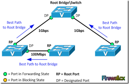
Now before we start looking into what criteria STP uses to put a port in Forwarding or Blocking state, let’s understand certain terminologies using the network diagram below:

clip_image001

Root Bridge: A switch with all its ports placed in Forwarding state is a root bridge. The Root Bridge is often called Root Switch.

Another way to think of the Root Bridge is as the Master Switch (for loop avoidance matters), for which only one active path must exist from all other switches, effectively avoiding any possible network loops.

Root Port: For a non–root switch, the port that connects this switch to the root switch, with the least cost, is called the root port.

Designated Port: A non – root port, which is forwarding away from the root switch, and has the lowest cost in that Ethernet segment, is called the designated port.

Cost: A port cost is defined by the speed at which the port operates. The cost of a port is inversely related to the associated bandwidth and therefore a port with a low cost value (greater bandwidth-speed) is more preferable than a port with high cost value (lower bandwidth-speed).

Note: The process of the Root Bridge election, Designated and Root Ports is covered in great detail in our Spanning Tree Protocol: Bridge ID, Priority, System ID Extension & Root Bridge Election Process articles.

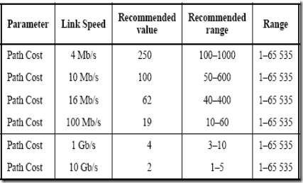
The table below was published by the IEEE group in 1998 and represented the cost against bandwidth:

clip_image002

The original STP Cost-Bandwidth table - Year 1998

The cost value (column marked “Range”) supported a 16-bit value (1 – 65535) while the root path cost was assigned a 32bit value embedded within the Bridge Protocol Data Unit (BPDU) field. BPDU's are special STP packets that contain all necessary information about the network's Spanning Tree topology.

In 2004, the revised 802.1D had its 16- bit path cost increased to a 32-bit value, providing more granularity:

clip_image003

STP uses the following criteria to decide whether to place a port in a Forwarding state or Blocking state

1. STP elects a Root Bridge, and then puts all its working interfaces in a Forwarding state

2. All other switches are now non–root switches. STP now looks at all the Root Ports from these switches, and finds the one with the Least Cost. Once this is found, STP places that interface in a Forwarding state.

3. Now STP finds all the Designated ports on the non–root switches, and places them in a Forwarding state.

4. Then STP places all other ports in a Blocking state.

It is absolutely essential to understand that the process of the Root Bridge and non-root switches election along with the port selection is performed only on working interfaces. Any failed/down interface i.e. no cables connected, or an interface which has been shutdown administratively, is parked into an STP Disabled state. Such ports are not considered during STP algorithm deployment.

Now let’s summarise what has been established previously:

Port Description

STP State

Important Observation

All ports on root switch

Forwarding

Root switch is always the designation switch on all Ethernet segment

Root ports on non – root switches

Forwarding

These are the ports that non – root switches use to reach the root switch

Every LAN’s designation port

Forwarding

The non – root port, that forwards away from the root switch, with lowest cost

All other working ports

Blocking

These ports are not used for forwarding, and any frames received on these interfaces are not forwarded as well.

The following table shows the available Port states for the original STP (802.1D) and newer Rapid STP (802.1w) designed to provide faster convergenceto topology changes. We should note that the three states Disabled, Blocking & Listening from STP (802.1D) have merged into one state, Discarding, for Rapid STP (802.1w):

STP (802.1D) Port State

RSTP (802.1w) Port State

Is Port Included in Active Topology?

Is Port Learning MAC Addresses?

Disabled

Discarding

No

No

Blocking

Discarding

No

No

Listening

Discarding

Yes

No

Learning

Learning

Yes

Yes

Forwarding

Forwarding

Yes

Yes

Support of Rapid STP (RSTP) in Cisco Catalyst Switches

This table shows the support of RSTP in Cisco Catalyst switches, and the minimum software required for that support. As a general rule of thumb, all newer Catalyst switches provide support for RTSP.

Catalyst Platform

MST w/ RSTP

RPVST+ (also known as PVRST+)

Catalyst 2900 XL / 3500 XL

Not available.

Not available.

Catalyst 2940

12.1(20)EA2

12.1(20)EA2

Catalyst 2950/2955/3550

12.1(9)EA1

12.1(13)EA1

Catalyst 2970/3750

12.1(14)EA1

12.1(14)EA1

Catalyst 3560

12.1(19)EA1

12.1(19)EA1

Catalyst 3750 Metro

12.1(14)AX

12.1(14)AX

Catalyst 2948G-L3/4908G-L3

Not available.

Not available.

Catalyst 4000/2948G/2980G (CatOS)

7.1

7.5

Catalyst 4000/4500 (IOS)

12.1(12c)EW

12.1(19)EW

Catalyst 5000/5500

Not available.

Not available.

Catalyst 6000/6500

7.1

7.5

Catalyst 6000/6500 (IOS)

12.1(11b)EX, 12.1(13)E, 12.2(14)SX

12.1(13)E

Catalyst 8500

Not available.

Not available.

In this article we covered Spanning Tree Protocol, Rapid STP port costs and port states. In our next article, we will start looking at how STP deploys the criteria. So, we will understand how STP decides which switch will be the Root Bridge , how it elects the Root Ports and Designated Ports. We will also investigate how STP reacts to any changes to the network topology and incorporates the changes in its algorithm.

Back to Spanning Tree Protocol Section

Taken From: http://www.firewall.cx/networking-topics/protocols/spanning-tree-protocol/1045-spanning-tree-protocol-port-costs-states.html

Spanning Tree – Principles

Spanning Tree Protocol – Understand STP Principles, Redundant Network Links & Broadcast Storms

Written by Arani Mukherjee. Posted in Spanning Tree Protocol (STP)

One of the most used terms in network is LAN (Local Area Network). It’s a form of network that we encounter in our daily lives, at home, at work, study, and in various other areas of life. Unless working specially in the field of Wide Area Networks (WAN), you will come across a LAN pretty much everyday. A key protocol used to maintain efficiency within a LAN is the Spanning Tree Protocol (STP), which is standardized as IEEE 802.1D. Without this protocol our LANs would rapidly become congested, with frames looping throughout the network infinitely, making network devices unstable. This protocol is implemented on switches, as switches deal with network data at the frame level. But before going ahead with a full blown explanation of what STP is, it is important to understand the ‘problem’ that STP prevents and how it improves a LAN’s performance. Let’s go through some salient features of a LAN first.

One of the most important devices within a LAN is a switch. All standard switches are Layer 2 devices i.e. they work at the level of frames. A frame is the unit of transmission in a link layer protocol and consists of a link-layer header followed by a packet. Without going into too much detail, a switch communicates in terms of frames. Users interested learning more about frames, can visit our Ethernet Frame Formats section where they'll find plenty of useful information and 3D representations of the various Ethernet frames. Apart from the higher layer data encapsulated by the frame, it carries two other important pieces of information, the Source MAC Address and the Destination MAC Address. It’s important to make a note of this as it becomes vital in our understanding of how a switch works and for STP itself.

How Does a Switch Work?

It must be noted that, before starting on this tutorial, it is best to have an understanding of how a switch works. If not then all is not lost. Users can always look up existing switch principles covered under the Switches & Bridges article.

Understanding of the following topics is essential for STP:

· How a switch finds MAC Addresses of new hosts

· How a switch populates its MAC Address tables

· How a switch deals with an incoming frame when it doesn’t know which outgoing interface to switch it to (due to no entry for a destination MAC Address in the switching table)

If the above fundamental principles are clear, learning about STP becomes simple.

Within permissible limits it might be said that STP is introduced within the LAN to prevent complications and network related problems caused by the way a switch functions. The flaw does not lie with how a switch works, it lies with the repercussions and manifestations of traffic because of it. Now let us run through some of the major issues encountered within a LAN.

Problems with Switches & Redundant Links

Just like our lives, LANs becomes big and complicated and cater to a huge number of devices. To provide interconnectivity and redundancy, sometimes switches are connected between themselves to ensure data streams are always maintained between network hosts. In an ideal world, a simple network would only have a router, a switch, and ‘n’ number of hosts connected to that switch, depending on how big the switch is. But just like Utopia, this ideal world doesn’t exist and networks have multiple switches, and sometimes these switches have interconnections. It’s done to provide redundant paths to various parts of the network to which these switches provide connectivity.

But by virtue of how a switch functions, there can be a few rather alarming issues cropping up very quickly when switches have more than one way of connecting various parts of the network. To visualise this concept, here’s a setup that has two hosts connected via two switches. For the sake of simplicity the router has been left out of this equation. Since STP is all about effective switching, let’s not involve ourselves in routing. The switching layout is, then, as follows:

To simplify this layout, please consider the following

· There are two switches, SW1 and SW2

· There are two hosts, PC1 and PC2, connected to SW1 and SW2 respectively

· MAC Address of PC1 is PC1-MAC1 and that of PC2 is PC2-MAC2

· SW1 and SW2 are connected to each other via 2 links, LINK 1 and LINK 2. These are redundant links

· For LINK1, the interface used on SW1 is SW1-MAC1, and the interface used on SW2 is SW2-MAC1

· For LINK2, the interface used on SW1 is SW1-MAC2, and the interface used on SW2 is SW2-MAC2

Now let’s look at a condition where both switches have an empty MAC address table. PC1 sends out a frame whose destination is PC2. This frame reaches SW1. Right now SW1 does not know which interface to use to forward this frame to PC2, so it does a broadcast. By virtue of frame forwarding, the source address of this frame now changes. Since this broadcast will go out through both LINK 1 and 2, the outgoing broadcast frames will have different source addresses.

Let us consider the frame from SW1 going out on LINK 1. Its destination address still reads PC2-MAC2. But its source address now reads SW1-MAC1. When this frame reaches SW2, SW2 does not know which interface to use to forward this frame to PC2-MAC2, so it does a broadcast. By virtue of a broadcast from a switch, this frame will not go out on LINK 1 again. This broadcasted frame goes out to PC2 and also goes out on LINK 2. Once PC2 receives this broadcast, it acknowledges receipt and SW2 learns the interface to use to forward a frame whose destination MAC Address says PC2-MAC2. But what about the broadcast frame that went out on LINK 2? This now reaches SW1, and its destination MAC Address still reads PC2-MAC2. SW1, for the second time, does not know which interface to use to forward this frame. So guess what it does? It does a broadcast again, causing PC1 to receive a frame it sent out in the first case.

So you see, an innocent frame that was destined for just one host on the other end of this simplified network, ended up with the host that sent it out in the first place. This is what is known as a broadcast storm. Now this process will keep on going till the network becomes congested with multiple duplicate frames, thus reducing its performance.

This is not the only issue on this LAN. What happens in the background is that the MAC table within both switches becomes extremely unstable. This is caused by the effect of the frame with the same destination MAC Address approaching the two switches with different source MAC Address. Hence the MAC table on each switch keeps getting updated without achieving any stable state. Not to mention the fact that due to this broadcast storm the hosts keep receiving multiple duplicate frames.

So to sum up, the issues encountered in the above situation are now made clear:

· Broadcast storm

· Unstable MAC Table in switches

· Multiple duplicate frames arriving at hosts

STP is aimed at resolving all the above issues. This is discussed in the next tutorial, Spanning Tree Protocol, Rapid STP Port Costs - Port States, where we will start discovering the working principle of this protocol, along with some key features and associated terms.

Back To Spanning Tree Protocol Section

Taken From: http://www.firewall.cx/networking-topics/protocols/spanning-tree-protocol/1042-spanning-tree-protocol-fundamentals.html

Thursday, April 3, 2014

HP ProCurve Switch - Reset and Basic Configuration

clip_image001

Reset switch to factory defaults

If I’m not using brand new switch, I normally like to reset it back to factory defaults before doing anything.
Use a pointy object (like paper clip) and press “Reset” and “Clear” buttons on the front of the switch at the same time.
Release “Reset” button. When “Self Test” LED start to blink, release “Clear” button too. Now the switch should do it test routines. After that it should be back on factory defaults.

IP-Address

HP ProCurve Switch 2524# configure
HP ProCurve Switch 2524(config)# vlan 1
HP ProCurve Switch 2524(vlan-1)# ip address 10.0.0.1 255.255.255.0
HP ProCurve Switch 2524(vlan-1)# wr mem
HP ProCurve Switch 2524(vlan-1)# exit
HP ProCurve Switch 2524(config)# exit
HP ProCurve Switch 2524#

Configure VLANs

HP ProCurve Switch 2524# configure
HP ProCurve Switch 2524(config)# vlan 1
HP ProCurve Switch 2524(vlan-1)# name "Default"
HP ProCurve Switch 2524(vlan-1)# untag 2-6
HP ProCurve Switch 2524(vlan-1)# vlan 10
HP ProCurve Switch 2524(vlan-10)# name "First"
HP ProCurve Switch 2524(vlan-10)# untag 7-12
HP ProCurve Switch 2524(vlan-10)# vlan 20
HP ProCurve Switch 2524(vlan-20)# name "Second"
HP ProCurve Switch 2524(vlan-20)# untag 13-18
HP ProCurve Switch 2524(vlan-20)# exit
HP ProCurve Switch 2524(config)# exit
HP ProCurve Switch 2524#

Set up trunk ports

HP ProCurve Switch 2524# config
HP ProCurve Switch 2524(config)# trunk 23-24 trk1
HP ProCurve Switch 2524(config)# vlan 10
HP ProCurve Switch 2524(vlan-10)# tagged trk1
HP ProCurve Switch 2524(vlan-10)# vlan 20
HP ProCurve Switch 2524(vlan-20)# tagged trk1
HP ProCurve Switch 2524(vlan-20)# wr mem
HP ProCurve Switch 2524(vlan-20)# exit
HP ProCurve Switch 2524(config)# exit
HP ProCurve Switch 2524#

Disable all (but trunk) ports

HP ProCurve Switch 2524# configure
HP ProCurve Switch 2524(config)# int 2-22 disable
HP ProCurve Switch 2524(config)# wr mem
HP ProCurve Switch 2524(config)# exit
HP ProCurve Switch 2524#

Enable only necessary ports

HP ProCurve Switch 2524# configure
HP ProCurve Switch 2524(config)# int 2-4 enable
HP ProCurve Switch 2524(config)# int 13-15 enable
HP ProCurve Switch 2524(config)# wr mem
HP ProCurve Switch 2524(config)# exit
HP ProCurve Switch 2524#

Set up speed etc.

HP ProCurve Switch 2524# configure
HP ProCurve Switch 2524(config)# int 2-4 speed-duplex 100-full
HP ProCurve Switch 2524(config)# int 13-15 speed-duplex auto
HP ProCurve Switch 2524(config)# wr mem
HP ProCurve Switch 2524(config)# exit
HP ProCurve Switch 2524#

Set time and date

Time and date on hh:mm and mm:dd:yyyy format

HP ProCurve Switch 2524# configure
HP ProCurve Switch 2524(config)# time 10:05
Mon Jan 1 10:05:28 1990
HP ProCurve Switch 2524(config)# time 08/24/2010
Tue Aug 24 10:05:41 2010
HP ProCurve Switch 2524(config)# wr mem
HP ProCurve Switch 2524(config)# exit
HP ProCurve Switch 2524#

Set hostname

HP ProCurve Switch 2524# configure
HP ProCurve Switch 2524(config)# hostname "ServerRoom1"
ServerRoom1(config)# wr mem
ServerRoom1(config)# exit
ServerRoom1#

Backup settings

After running “sh run” copy/paste all between line which start with “hostname” to “ServerRoom1#” example to notepad and save that file.

ServerRoom1# sh run
ServerRoom1#

Restore settings from backup

All you have to do is copy/paste all (except the first “Running configuration:” line) to notepad on “Backup settings” part to “HP ProCurve Switch 2524#”.
If you have set operator and/or manager passwords, don’t copy/paste the lines which start with password.

HP ProCurve Switch 2524# configure
HP ProCurve Switch 2524(config)#

Set manager and operator password

ServerRoom1# configure
ServerRoom1(config)# password all
New password for Operator: ********
Please retype new password for Operator: ********
New password for Manager: ********
Please retype new password for Manager: ********
ServerRoom1(config)#

Update firmware using tftp server

If you are using windows machine and need tftp server software, you should try 3CDaemon. It’s free, portable, and it works like a dream =)

Download newest firmware from HP’s website: Software for switches.
For my switch HP ProCurve 2524gl, newest firmware was F.05.72. I downloaded 2300_2500-Software-F0572.zip package and extracted it to “2300_2500-Software-F0572″ folder.

Now I have directory “2300_2500-Software-F0572″ with 2300_2500-RelNotes-F0572-59903102.pdf (Release Notes). I also have F_05_72.swi file and this .swi file is the firmware which you are going to use to update your switch.

ServerRoom1# configure
ServerRoom1(config)# copy tftp flash 10.0.0.100 F_05_72.swi
Device will be rebooted, do you want to continue [y/n]? y
00126K

After F_05.72.swi is copied to the switch, you should get this kind of line. When eve everything goes ok your switch will reboot itself:

Validating and Writing System Software to FLASH...

Update firmware using xmodem over serial connection

I normally use Microsoft Hyperterminal when I’m doing this because it’s pretty easy to use xmodem to upload files with hyperterminal

Download newest firmware from HP’s website: Software for switches For my switch HP ProCurve 2524gl newest firmware was F.05.72 so I downloaded 2300_2500-Software-F0572.zip package and extracted it to “2300_2500-Software-F0572″.

Now I have directory “2300_2500-Software-F0572″ with 2300_2500-RelNotes-F0572-59903102.pdf (Release Notes) and F_05_72.swi file and this .swi file is the firmware which you are going to use to update your switch)

HP ProCurve Switch 2524# configure
HP ProCurve Switch 2524(config)# copy xmodem flash
The Primary OS Image will be deleted, continue [y/n]? y
Press 'Enter' and start XMODEM on your host...

After hitting ‘Enter’, start uploading using hyperterminal from menu: “Transfer” => “Send File…” then click “Browse…” and find that F_05_72.swi file and choose Xmodem (Not “1K Xmodem”) protocol. Then hit “Send” button. When everything is done you should see this kind of message and after that switch should boot:

Validating and Writing System Software to FLASH...

[note]This configuration was done with HP ProCurve 2524 (J4813A) but most of this command should work with other procurve switches too.[/note]

Related posts:

  1. HP ProCurve CLI CheatSheet
  2. How to reset Cisco Catalyst 2948G-L3 Switch
  3. Raspberry Pi: Get GPS Working with Kismet
  4. Raspberry Pi: Wireless Network

Taken From: http://blog.petrilopia.net/info/configuring-hp-procurve-switch/

Monday, January 6, 2014

Private VLANs - Trunks and SVIs (Cisco)

Private VLANs on Trunks and SVIs

By stretch | Thursday, October 28, 2010 at 1:41 a.m. UTC

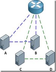
This article examines the function of private VLANs across 802.1Q trunk links (not to be confused with configuring private VLAN trunk ports, which are supported only on the Catalyst 4500 and 6500 series) and how they can be mapped to SVIs for multilayer switching. For a review of private VLAN fundamentals, check outBasic Private VLAN Configuration. We'll be using the example topology below as a reference.

clip_image002

Our private VLAN configuration on S1 and S2 looks like this (if you're following along in a lab, note that the community VLANs 101 and 102 must be createdbefore being associated with the primary VLAN 100):

vlan 100

private-vlan primary

private-vlan association 101-102

vlan 101

private-vlan community

vlan 102

private-vlan community

Here are the physical interface configurations per switch for your reference:

S1

interface FastEthernet0/1

switchport private-vlan mapping 100 101-102

switchport mode private-vlan promiscuous

!

interface FastEthernet0/3

switchport private-vlan host-association 100 101

switchport mode private-vlan host

!

interface FastEthernet0/5

switchport private-vlan host-association 100 102

switchport mode private-vlan host

!

interface FastEthernet0/13

switchport trunk encapsulation dot1q

switchport mode trunk

S2

interface GigabitEthernet0/4

switchport private-vlan host-association 100 101

switchport mode private-vlan host

!

interface GigabitEthernet0/6

switchport private-vlan host-association 100 102

switchport mode private-vlan host

!

interface GigabitEthernet0/13

switchport trunk encapsulation dot1q

switchport mode trunk

Note that there is nothing special about the trunk configuration; both ends are configured as typical 802.1Q trunk interfaces.

Trunking

With the configurations above applied, the router is able to communicate with all hosts, and all hosts are able to communicate with the router and with the other host in their respective community private VLANs (e.g. host A can reach the router and host B, but not host C or D).

clip_image004

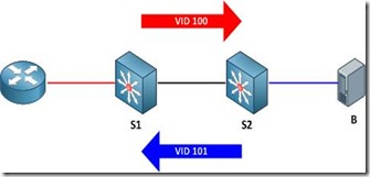
Of course, good network engineers aren't satisfied simply knowing that something works: we want to know how it works. This functionality is actually achieved by bending some rules about VLAN assignments. Traditionally, you expect return traffic originating within a VLAN to come back over the trunk tagged with that same VLAN ID. This is not always the case with private VLANs.

When the router sends a frame to one of the hosts on S2, the frame is tagged as belonging to the primary VLAN 100 when it traverses the trunk, because the router is attached to a promiscuous port. Frames originating from the hosts, however, are tagged with their appropriate secondary VLAN IDs. A frame from host B back to the router, for example, is tagged as VLAN 101 when traversing the trunk link.

clip_image006

To summarize:

· Frames originating from a promiscuous port are tagged with the primary VLAN ID

· Frames originating from a host port are tagged with the secondary (isolated or community) VLAN ID

And of course, here's a packet capture to help drive the idea home.

SVIs

What if we wanted to remove the router from our topology and do all inter-VLAN routing locally on our multilayer switch S1? No problem, we just need to create the primary VLAN SVI (switched virtual interface, also commonly referred to as a VLAN interface) and apply to it a mapping for our secondary VLANs. First we'll shut down the interface connected to the router and enable multilayer switching.

S1(config)# interface f0/1

S1(config-if)# shutdown

S1(config-if)# exit

S1(config)# ip routing

Next, we'll create the SVI for VLAN 100, assign it the IP address which was previously assigned to the router, and map our secondary VLANs.

S1(config)# interface vlan100

S1(config-if)# ip address 192.168.0.1 255.255.255.0

S1(config-if)# private-vlan mapping 101-102

S1(config-if)#

%PV-6-PV_MSG: Created a private vlan mapping, Primary 100, Secondary 101

%PV-6-PV_MSG: Created a private vlan mapping, Primary 100, Secondary 102

S1 now functions in place of the external router; all hosts can reach its routed Vlan100 interface but are still restricted to communicating with hosts in their secondary VLAN.

clip_image007

About the Author

Jeremy Stretch is a network engineer living in the Raleigh-Durham, North Carolina area. He is known for his blog and cheat sheets here at Packet Life. You can reach him by email or follow him on Twitter.

Taken From: http://packetlife.net/blog/2010/oct/28/private-vlans-trunks-and-svis/

Thursday, March 15, 2012

Enterasys Switches Crash Course

[ Login & Password ]

If admin / siemens doesn't work, try admin/none
default, no pwd, just enter
user : admin, rw, ro


C2(SU)-> set system login 'username' {super-user|read-write|read-only}{enale|disable}
C2(SU)-> clear system login 'username'
C2(SU)-> show system login
for rw and ro = set password
for admin = set system login
C2(SU)-> set password rw
C2(SU)-> set system password length 7


[ Assign IP address ]

C2(SU)-> set ip address x.x.x.x mask x.x.x.x gateway x.x.x.x
C2(SU)-> clear ip address
[ Webview ]

Default : enable
C2(SU)-> show webview : to see status of webview (default enable)
C2(SU)-> set webview enable : to enable webview
- login : http://172.16.2.10
C2(SU)-> show webview
WebView is Enabled


[ Set time ]
C2(SU)-> set time 7:50:00
C2(SU)-> set summertime enable

[ Set prompt ]
C2(SU)-> set prompt "switch 1"

[ Set system contact ]
C2(SU)-> set system name "Enterasys-C2.1"
C2(SU)-> set system location "Main Bldg 2nd Floor"
C2(SU)-> set system contact "ipBalance Admin (            888-999-0000      )Mr.admin@ipBalance.com This e-mail address is being protected from spambots. You need JavaScript enabled to view it "

[ Save configuration ]
C2(SU)-> save config

[ Configure ]
C2(SU)-> configure configs/Jan1_2004.cfg

[ Set command ]
C2(SU)-> set switch description 1 : describe switch name or location
C2(SU)-> set ip address {x.x.x.x} mask {255.255.255.0} gateway {x.x.x.x}
C2(SU)-> clear ip address
C2(SU)-> set time [mm/dd/yyyy][hh:mm:ss]
C2(SU)-> set logout 10 : closing session idle in 10 min
C2(SU)-> set port [enable|diable]
C2(SU)-> set port duplex
C2(SU)-> set cdp state disable fe.1.2
C2(SU)-> set cdp state disable fe.1.3
C2(SU)-> set vlan create 2
C2(SU)-> set vlan create 3
C2(SU)-> set vlan name 1 Management
C2(SU)-> set vlan egress 1 fe.1.1 tagged
C2(SU)-> set vlan egress 1 fe.1.22 untagged
C2(SU)-> set vlan egress 2 fe.1.1 tagged
C2(SU)-> set vlan egress 2 fe.1.2-14 untagged
C2(SU)-> set port alias fe.1.1 'To Computer room N1.1 Port 2'
C2(SU)-> set port vlan fe.1.14 2

[ show ]
C2(SU)-> show config port
C2(SU)-> show switch
C2(SU)-> show switch status 1
C2(SU)-> show system
C2(SU)-> show system hardware : to get serial#, MAC, Firmware version etc
C2(SU)-> show system utilization {cpu|storage}
C2(SU)-> show time
C2(SU)-> show console
C2(SU)-> show telnet
C2(SU)-> show system login : user login account info
C2(SU)-> show system lockout
C2(SU)-> show ip address
C2(SU)-> show ip protocol : shown "system IP address acquisition method: dhcp
C2(SU)-> show config port
C2(SU)-> show cdp
C2(SU)-> show port fe.1.14 (ex, show port *.*.*)
C2(SU)-> show port status fe.1.14 : shown on status of information for fe.1.14
C2(SU)-> show port counters fe.1.14
C2(SU)-> show port negotiation fe.1.14
C2(SU)-> show port broadcast fe.1.14
C2(SU)-> show spantree stats
C2(SU)-> show boot system

[ Lag ]
C2(SU)-> show lacp lag 0.1
C2(SU)-> set lacp enable
C2(SU)-> set lacp asyspri 1000
C2(SU)-> set lacp aadminkey lag.0.1 2000
C2(SU)-> set lacp static lag.0.6 fe.1.6
C2(SU)-> set lacp singleportlag enable
C2(SU)-> set port lacp fe.3.16 aadminkey 3555

[ Clear ]
C2(SU)-> clear config
C2(SU)-> clear vlan 3
C2(SU)-> clear vlan name 9
C2(SU)-> clear port vlan fe.1.3,fe.1.11
C2(SU)-> clear vlan egress 1 fe2.1
C2(SU)-> clear VNRAM

[ Reset ]
C2(SU)-> reset or reset 1 : reload switch 1

[ Configuration example ]
C2(SU)-> dir
C2(SU)-> show configuration outfile configs/
C2(SU)-> copy configs/ tftp://192.168.77.101/
using notepad, modify config
C2(SU)-> copy tftp://192.168.77.101/jan11_2006.cfg configs/jan11_2006.cfg
C2(SU)-> dir
C2(SU)-> configure configs/  : unit will reboot onto the modified config file
C2(SU)-> configure configs/Jan11_2006.cfg  :  to execute the"jan11_2006.cfg" configurationn file
C2(SU)-> delete configs/jan11_2006.cfg
C2(SU)-> clear config all
C2(SU)-> clear NVRAM
C2(SU)-> show snmp persistmode manual : manual save config
C2(SU)-> save config

[ Login & Password ]

If admin / siemens doesn't work, try admin/none
default, no pwd, just enter
user : admin, rw, ro

A2(SU)-> set system login 'username' {super-user|read-write|read-only}{enale|disable}
A2(SU)-> clear system login 'username'
A2(SU)-> show system login
for rw and ro = set password
for admin = set system login
A2(SU)-> set password rw
A2(SU)-> set system password length 7

[ Assign IP address ]
A2(SU)-> set ip address x.x.x.x mask x.x.x.x gateway x.x.x.x
A2(SU)-> clear ip address

[ Webview ]
Default : enable
A2(SU)-> show webview : to see status of webview (default enable)
A2(SU)-> set webview enable : to enable webview
- login : http://172.16.2.10
A2(SU)-> show webview
WebView is Enabled
[ Set time ]
A2(SU)-> set time 7:50:00
A2(SU)-> set summertime enable
[ Set prompt ]
A2(SU)-> set prompt "switch 1"
[ Set system contact ]
A2(SU)-> set system name "Enterasys-A2.1"
A2(SU)-> set system location "Main Bldg 2nd Floor"
A2(SU)-> set system contact "ipBalance Admin (            888-999-0000      ) Mr.admin@ipBalance.com "
 
[ Save configuration ]

A2(SU)-> save config

[ Configure ]
A2(SU)-> configure configs/Jan1_2004.cfg
[ Set command ]
A2(SU)-> set switch description 1 : describe switch name or location
A2(SU)-> set ip address {x.x.x.x} mask {255.255.255.0} gateway {x.x.x.x}
A2(SU)-> clear ip address
A2(SU)-> set time [mm/dd/yyyy][hh:mm:ss]
A2(SU)-> set logout 10 : closing session idle in 10 min
A2(SU)-> set port [enable|diable]
A2(SU)-> set port duplex
A2(SU)-> set cdp state disable fe.1.2
A2(SU)-> set cdp state disable fe.1.3
A2(SU)-> set vlan create 2
A2(SU)-> set vlan create 3
A2(SU)-> set vlan name 1 Management
A2(SU)-> set vlan egress 1 fe.1.1 tagged
A2(SU)-> set vlan egress 1 fe.1.22 untagged
A2(SU)-> set vlan egress 2 fe.1.1 tagged
A2(SU)-> set vlan egress 2 fe.1.2-14 untagged
A2(SU)-> set port alias fe.1.1 'To Computer room N1.1 Port 2'
A2(SU)-> set port vlan fe.1.14 2
[ show ]
A2(SU)-> show config port  :
A2(SU)-> show switch
A2(SU)-> show switch status 1
A2(SU)-> show system
A2(SU)-> show system hardware : to get serial#, MAC, Firmware version etc
A2(SU)-> show system utilization {cpu|storage}
A2(SU)-> show time
A2(SU)-> show console
A2(SU)-> show telnet
A2(SU)-> show system login : user login account info
A2(SU)-> show system lockout
A2(SU)-> show ip address
A2(SU)-> show ip protocol : shown "system IP address acquisition method: dhcp
A2(SU)-> show config port
A2(SU)-> show cdp
A2(SU)-> show port fe.1.14 (ex, show port *.*.*)
A2(SU)-> show port status fe.1.14 : shown on status of information for fe.1.14
A2(SU)-> show port counters fe.1.14
A2(SU)-> show port negotiation fe.1.14
A2(SU)-> show port broadcast fe.1.14
A2(SU)-> show spantree stats
A2(SU)-> show boot system
[ Lag ]
A2(SU)->
show lacp lag 0.1
A2(SU)-> set lacp enable
A2(SU)-> set lacp asyspri 1000
A2(SU)-> set lacp aadminkey lag.0.1 2000
A2(SU)-> set lacp static lag.0.6 fe.1.6
A2(SU)-> set lacp singleportlag enable
A2(SU)-> set port lacp fe.3.16 aadminkey 3555
[ Clear ]
A2(SU)-> clear config
A2(SU)-> clear vlan 3
A2(SU)-> clear vlan name 9
A2(SU)-> clear port vlan fe.1.3,fe.1.11
A2(SU)-> clear vlan egress 1 fe2.1
A2(SU)-> clear VNRAM
[ Reset ]
A2(SU)-> reset or reset 1 : reload switch 1

[ Configuration example ]
A2(SU)-> dir
A2(SU)-> show configuration outfile configs/
A2(SU)-> copy configs/ tftp://192.168.77.101/
using notepad, modify config
A2(SU)-> copy tftp://192.168.77.101/jan11_2006.cfg configs/jan11_2006.cfg
A2(SU)-> dir
A2(SU)-> configure configs/  : unit will reboot onto the modified config file
A2(SU)-> configure configs/Jan11_2006.cfg  :  to execute the"jan11_2006.cfg" configurationn file
A2(SU)-> delete configs/jan11_2006.cfg
A2(SU)-> clear config all
A2(SU)-> clear NVRAM
A2(SU)-> show snmp persistmode manual : manual save config
A2(SU)-> save config

[ Default Login & Password ]
Here is default  login passwords of the most Enterasys Switches.
A-Series, B-Series and C-Series Enterasys Switches.
User : admin
Password : [empty]
Try below commends to see current login

Enterasys_A2(SU)-> show system login
Password history size: 0 
Password aging        : disabled  
Username     Access           State  
admin          super-user      enabled 
ro               read-Only       enabled 
rw              read-write       enabled
To add user 'Chris' as a super-user
  Enterasys_A2(SU)-> set system login chris super-user enable
  Enterasys_A2(SU)-> show system login

Password history size: 0
Password aging        : disabled
Username     Access           State
admin       super-user          enabled
ro            read-Only           enabled
rw           read-write           enabled
chris         super-user           enabled
To delete user 'chris' from list

  Enterasys_A2(SU)-> clear system login chris

If you want to change password length 7
  Enterasys_A2(SU)-> set system password length 7

[ Syslog Server ]
While I was testing Splunk, I need to add more devices to Splunk index pages. This example shows how to configure Enterasys Switch to forward syslog message to the server. It's simple and easy to setup.
In this example, server's IP is 192.168.77.13 and UDP port 514 is used. Severity level is 8.

  Enterasys(su)>set logging server 1 ip-addr 192.168.77.12 port 514 severity 8 state enable

To verify

 
  Enterasys(su)>show logging server

IP Address    Facility   Severity      Description  Port  Status 
--------------------------------------------------------------- 1 192.168.77.12    local4    debugging(8)     default     514   enable
If you want to change default value to facility local 5 and severity 5, configure below.

Enterasys(su)>set logging default facility local 5 severity 5
To see currently logging severity levels for all applications on your devices, type below commands

Enterasys(su)>show logging application all

        Application   Current Severity Level
---------------------------------------------
89      CLIWEB                   6
90      SNMP                     6
91      STP                      6
92      Driver                   6
93      System                   6
94      Stacking                 6
112     UPN                      6
118     Router                   6
1(emergencies)  2(alerts)       3(critical)
4(errors)       5(warnings)     6(notifications)
7(information)  8(debugging)

[ Port Mirroring ]
source port 1/13
destinaion port 1/10

Console(Config)#interface Ethernet 1/1
Console(Config-if)#port monitor Ethernet 1/4
Console(Config-if)#

[ Upgrade Firmware ]
As you know Enterasys was named Cabletron company long long time ago. I guess more than decade Cabletron was one of strong vendor on switches market at that time. Due to I had really good experience with Cabletron product, I trust Enterasys's product line. Actually, I installed many Enterasys switches since 2005. Today, I just want to share a tip to upgrade firmware on Enterasys switches. Compare to generic 3rd party switch vendors, Enterasys release new firmware more often. Well, some of people might say due to all lot of bugs, but I like to say "Diligent and effort" (too much?).There are detailed documents from vendor, but this guide would be easier for beginner. Well, lets see what the steps to complete upgrading firmware are.
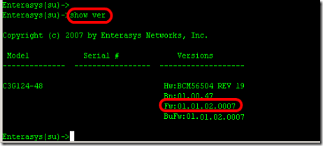
1. Find out what model of switch you are upgrading and what is current version of firmware running on the switch. Type "Show version" from the prompt.

- Model : C3G124-48
- Firmware : 01.01.02.0007

clip_image005
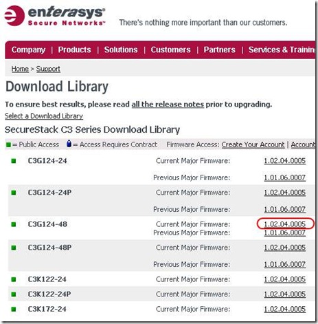
2. Go to the website "www.enterasys.com" and download proper firmware from the download library. and extract firmware to any folder your tftp server will use.

clip_image007

3. Assign IP address on the Enterasys switch in order to communicate with you computer which is running tftp server.
ex) computer 192.168.1.47, Enterasys switch is 192.168.1.8, default gateway .254

"set ip address 192.168.1.8 mask 255.255.255.0 gateway 192.168.1.254"


clip_image008
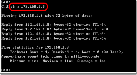
4. Ping the Enterasys switch from your computer.

clip_image009
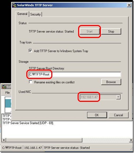
5. Execute tftp server. (If you don't have, just down one from solarwinds)

clip_image011
6. Copy firmware from tftp server

Enterasys(su)->copy tftp://192.168.1.47/c3-series_01.02.04.0005 system:image
- I will take time...to be done (few minutes)

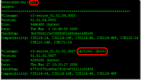
7. From the switch, make sure new firmware is uploaded and check which firmware version is on active.

clip_image012
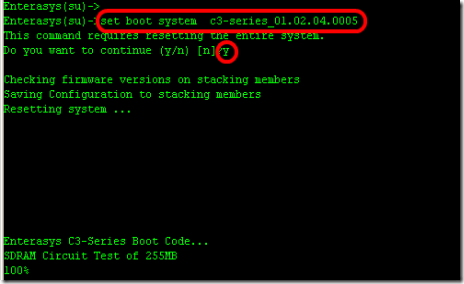
8. Type to "set boot system c3-series_01.02.04.0005" to booting up switch with new firmware(active).
B2(su)>>set boot system c3-series_01.02.04.0005
Do you want to replace ? (y/n) y
Automatically Enterasys switch will reboot.

clip_image013

9. Confirm now, new firmware is on active status.
The complete CLI reference manuals can be found at:

Enterasys C2 (Configuration Guide) :
http://www.penteknoloji.com.tr/destek/c2/1.pdf
Enterasys C3 (Configuration Guide): http://www.penteknoloji.com.tr/destek/c3/2.pdf