Showing posts with label cisco. Show all posts

Saturday, August 17, 2013

Cisco VLC Multicast Streaming Demo – PIM Sparse Mode

Topology

[Multicast-realdemo.jpg]

Howto

Configurations

This is the how to for this lab: here
R1
!
ip multicast-routing
!
!
interface Loopback0
ip address 1.1.1.1 255.255.255.255
ip pim sparse-mode
!
interface FastEthernet1/0
description wan
ip address 10.0.12.1 255.255.255.0
ip pim sparse-mode
duplex auto
speed auto
!
interface FastEthernet2/0
description lan
ip address 192.168.1.1 255.255.255.0
ip pim sparse-mode
duplex auto
speed auto
!
router ospf 1
router-id 1.1.1.1
log-adjacency-changes
network 1.1.1.1 0.0.0.0 area 1
network 10.0.12.0 0.0.0.255 area 0
network 10.0.13.0 0.0.0.255 area 0
network 192.168.1.0 0.0.0.255 area 1
!
!Define this router as a RP
ip pim rp-candidate Loopback0
!


R2

ip multicast-routing
!
interface Loopback0
ip address 2.2.2.2 255.255.255.255
ip pim sparse-mode
!
!
interface FastEthernet1/0
description wan
ip address 10.0.12.2 255.255.255.0
ip pim sparse-mode
duplex auto
speed auto
!
interface FastEthernet1/1
description lan
ip address 192.168.2.2 255.255.255.0
ip pim sparse-mode
duplex auto
speed auto
!
router ospf 1
router-id 2.2.2.2
log-adjacency-changes
network 2.2.2.2 0.0.0.0 area 2
network 10.0.12.0 0.0.0.255 area 0
network 192.168.2.0 0.0.0.255 area 2
!
!Define router as a Bootstrap Router Candidate
ip pim bsr-candidate Loopback0 0

!

Note:
ip pim bsr-candidate and ip pim rp-candidate can both be added to the same router if you wish. Therefore in this lab we could of defines both on R1 and left R2 with only ip pim sparseon its interfaces.
Here are the batch files used in VLC:
StartMulticast.bat:

"C:\Program Files\VideoLAN\VLC\vlc.exe" -vvv test.m4v :sout=#transcode{vcodec=h264,vb=800,scale=1,acodec=mp4a,ab=128,channels=2,samplerate=44100}:std{access=udp,mux=ts,dst=239.0.0.1:1234} --ttl 12

StartVideo.bat

call "C:\Program Files\VideoLAN\VLC\vlc.exe" -vvv udp://@239.0.0.1:1234

Taken From: http://roggyblog.blogspot.pt/2009/10/multicast-lab-with-vlc-howto.html

For info on setting up VLC via the graphical interface check out this post: http://myhowtosandprojects.blogspot.pt/2013/08/vlc-multicast-streaming.html

Saturday, August 10, 2013

Cisco IOS on UNIX (IOU) - Installing and Running (Lite)

Cisco IOS on UNIX (IOU) is a fully working version of IOS that runs as a user mode UNIX/LINUX process. IOU is built as a native system image and run just like any other program. IOU supports all platform independent protocols and features.

With regard to functionality, it is very similar to GNS3 but it does not require nearly the resources that several virtual routers running under dynamips does.
IOU allows you to build out a network topology on a single PC without the need for physical routers. This is useful for validating network designs, proof-of-concept testing, and certification self-study.

Legal Warnings

If you are not an authorized Cisco employee (or trusted partner), usage of Cisco IOU is prohibited. From an old, internal-only Cisco web page:
Cisco IOS on Unix is a tool intended for internal use only. Distribution of IOU images to customers or external persons, or discussion of IOU with customers or external persons, is prohibited. Don’t do it or we’ll have to come and kill you.
Cisco IOU, just like IOS, is copyrighted software that belongs to cisco Systems, Inc. Distribution of copyrighted software is a federal crime in the United States. I cannot speak regarding the laws of other countries.
In addition, any requests for Cisco IOU images in the comments section of this blog will be deleted, regardless if distribution is legal in your country.
 
Installing and Running IOU

Checking the Distro
$ cat /etc/issue
Ubuntu 11.04 \n \l


Checking the CPU
$ uname -a
Linux ltsp180 2.6.38-13-generic #55-Ubuntu SMP Tue Jan 24
15:34:24 UTC 2012 x86_64 x86_64 x86_64 GNU/Linux


Installing 32 bit Libs on a 64 bit Distro
$ sudo apt-get install ia32-libs

Installing BBE
$ sudo apt-get install bbe

OR

http://packages.ubuntu.com/
- Your distro | Editors | BBE

Download the file (bbe\_0.2.2-1\_i386.deb)
And install it manually

$ sudo dpkg -i bbe_0.2.2-1_i386.deb

Installing and Linking the "libcrypto" Library
You either do not have libssl installed or your version is much newer than what Cisco has linked against when building the IOU images.
First, ensure that libssl is installed. On Debian and Ubuntu:

$ sudo apt-get install libssl0.9.8
Next, youll need to make a symbolic link pointing to the "libcrypto.so.4" file that IOU is looking for.

On 32-bit distros:
$ sudo ln -s /usr/lib/libcrypto.so.0.9.8 /usr/lib/libcrypto.so.4

On 64-bit distros:
$ sudo ln -s /usr/lib32/libcrypto.so.0.9.8 /usr/lib32/libcrypto.so.4

NETMAP File
The network topology map, or NETMAP, file describes the topology of your virtual network. It is used for controlling the layout of the virtual cabling. If you have used dynagen, this is the equivalent of the .net file.

NETMAP
----------------

100:0/0 200:0/1

The above netmap file means that you are connecting port 0/0 of router 100, to port 0/1 of router 200:

[Router 100]--Ethernet 0/0------Ethernet 0/1--[Router 200]

Checking the Hostname For the "iourc" File
$ hostname -s
chaos


The "iourc" File
iourc
-------------------------
[license]
chaos = 4C5556554353434F;


The IOURC file is a configuration file for Cisco IOU. Cisco IOU looks in this file for your license key at startup.

Note: The method below for patching the IOU image for your machine's hostname, implies that, the license is "4C5556554353434F" and the only change is the hostname.

Giving Execution Permitions to the IOU Image
$ chmod +x i86*

Executing the IOU Image For Router 100 - Non Patched
$ ./i86bi_linux-adventerprisek9-ms.151-4.M 100
***************************************************************
IOS On Unix - Cisco Systems confidential, internal use only
Under no circumstances is this software to be provided to any
non Cisco staff or customers. To do so is likely to result
in disciplinary action. Please refer to the IOU Usage policy at
wwwin-iou.cisco.com for more information.
***************************************************************
IOU License Error: invalid license
License for key 7f030f required on host ?chaos?.
Obtain a license for this key and host from the following location:
http://wwwin-enged.cisco.com/ios/iou/license/index.html
Place in your iourc file as follows (see also the web page
for further details on iourc file format and location)
[license]
chaos = <16 char license>;
This attempt didn't work because the IOU image hasn't been patched for your hostname

Patching IOU Image For Key "4C5556554353434F"

$ for F in i86bi_linux-*;do bbe -b "/\xfc\xff\x83\xc4\x0c\x85\xc0\x75\x14\x8b/:10"
-e "r 7 \x90\x90" -o $F.x $F;mv $F.x $F;done;chmod +x ./i86bi_linux-*

Note: This works for the following IOU images (didn’t worked for Layer 2 Images):

  • i86bi_linux-adventerprisek9-ms
  • i86bi_linux-ipbase-ms
For the i86bi_linuxl2-upk9-ms, you need to use something like IOUGEN.

Executing the IOU Image For Router 100 - Patched IOU
$ ./i86bi_linux-adventerprisek9-ms 100
***************************************************************
IOS On Unix - Cisco Systems confidential, internal use only
Under no circumstances is this software to be provided to any
non Cisco staff or customers. To do so is likely to result
in disciplinary action. Please refer to the IOU Usage policy at
wwwin-iou.cisco.com for more information.
***************************************************************
Port 0 is not connected to anything
Restricted Rights Legend
Use, duplication, or disclosure by the Government is
subject to restrictions as set forth in subparagraph
(c) of the Commercial Computer Software - Restricted
Rights clause at FAR sec. 52.227-19 and subparagraph
(c) (1) (ii) of the Rights in Technical Data and Computer
Software clause at DFARS sec. 252.227-7013.
cisco Systems, Inc.
170 West Tasman Drive
San Jose, California 95134-1706
Cisco IOS Software, Linux Software (I86BI_LINUX-ADVENTERPRISEK9-M),
Version 15.1(4)M, DEVELOPMENT TEST SOFTWARE
Technical Support: http://www.cisco.com/techsupport
Copyright (c) 1986-2011 by Cisco Systems, Inc.
Compiled Fri 25-Mar-11 16:44 by prod_rel_team
This product contains cryptographic features and is subject to United
States and local country laws governing import, export, transfer and
use. Delivery of Cisco cryptographic products does not imply
third-party authority to import, export, distribute or use encryption.
Importers, exporters, distributors and users are responsible for
compliance with U.S. and local country laws. By using this product you
agree to comply with applicable laws and regulations. If you are unable
to comply with U.S. and local laws, return this product immediately.
A summary of U.S. laws governing Cisco cryptographic products may be found at:
http://www.cisco.com/wwl/export/crypto/tool/stqrg.html
If you require further assistance please contact us by sending email to
export@cisco.com.
Warning: the compile-time code checksum does not appear to be present.
Linux Unix (Intel-x86) processor with 140260K bytes of memory.
Processor board ID 2048042
8 Ethernet interfaces
8 Serial interfaces
64K bytes of NVRAM.

Executing the IOU Image For Router 200 - Patched IOU
$ ./i86bi_linux-adventerprisek9-ms 200
***************************************************************
IOS On Unix - Cisco Systems confidential, internal use only
Under no circumstances is this software to be provided to any
non Cisco staff or customers. To do so is likely to result
in disciplinary action. Please refer to the IOU Usage policy at
wwwin-iou.cisco.com for more information.
***************************************************************
Port 0 is not connected to anything
Restricted Rights Legend
Use, duplication, or disclosure by the Government is
subject to restrictions as set forth in subparagraph
(c) of the Commercial Computer Software - Restricted
Rights clause at FAR sec. 52.227-19 and subparagraph
(c) (1) (ii) of the Rights in Technical Data and Computer
Software clause at DFARS sec. 252.227-7013.
cisco Systems, Inc.
170 West Tasman Drive
San Jose, California 95134-1706
Cisco IOS Software, Linux Software (I86BI_LINUX-ADVENTERPRISEK9-M),
Version 15.1(4)M, DEVELOPMENT TEST SOFTWARE
Technical Support: http://www.cisco.com/techsupport
Copyright (c) 1986-2011 by Cisco Systems, Inc.
Compiled Fri 25-Mar-11 16:44 by prod_rel_team
This product contains cryptographic features and is subject to United
States and local country laws governing import, export, transfer and
use. Delivery of Cisco cryptographic products does not imply
third-party authority to import, export, distribute or use encryption.
Importers, exporters, distributors and users are responsible for
compliance with U.S. and local country laws. By using this product you
agree to comply with applicable laws and regulations. If you are unable
to comply with U.S. and local laws, return this product immediately.
A summary of U.S. laws governing Cisco cryptographic products may be found at:
http://www.cisco.com/wwl/export/crypto/tool/stqrg.html
If you require further assistance please contact us by sending email to
export@cisco.com.
Warning: the compile-time code checksum does not appear to be present.
Linux Unix (Intel-x86) processor with 140260K bytes of memory.
Processor board ID 2048042
8 Ethernet interfaces
8 Serial interfaces
64K bytes of NVRAM.
If you dont need/want to have access to the equipments via network (telnet) this is enough, for you, add a couple more equipments and connections to the NETMAP file you are good to go.

IOU Image Options
./i86bi_linux-adventerprisek9-ms
Usage: <image> [options] <application id>
<image>: unix-js-m | unix-is-m | unix-i-m | ...
<application id>: instance identifier (0 < id <= 1024)
Options:
-e <n> Number of Ethernet interfaces (default 2)
-s <n> Number of Serial interfaces (default 2)
-n <n> Size of nvram in Kb (default 16KB)
-b <string> IOS debug string
-c <name> Configuration file name
-d Generate debug information
-t Netio message trace
-q Suppress informational messages
-h Display this help
-C Turn off use of host clock
-m <n> Megabytes of router memory (default 128MB)
-L Disable local console, use remote console
-u <n> UDP port base for distributed networks
-R Ignore options from the IOURC file
-U Disable unix: file system location
-W Disable watchdog timer
-N Ignore the NETMAP file

NVRAM Files
The IOU instances on the above example created the following files:
  • nvram_00100 -->Router 100
  • nvram_00200 -->Router 200

as you migth recall the nvram, is the were the startup-config is stored so these files are more or less the startup config for router 100 and 200.

If you type:
$ cat nvram_00100
????
!
version 12.4
service timestamps debug datetime msec
service timestamps log datetime msec
no service password-encryption
!
hostname Router100
!
boot-start-marker
boot-end-marker
<...>
you can see the startup-config, plus a bit off jiberish.

TSHOOT - Cisco IOU Error Messages

  • What does ``UNIX ERR:tcgetattr:Invalid argument''mean? Im not sure, honestly, but it doesnt seem to hurt anything or cause any loss of functionality. It appears that it can be safely ignored.
  • i86bi_linux_adventerprisek9-ms: No such file or directory Youre probably running a 64-bit version of Linux. On Debian and Ubuntu, installing the ia32-libs package will fix this for you (for other distros, youre on your own):

$ sudo apt-get install ia32-libs

  • i86bi_linux_adventerprisek9-ms: error while loading shared libraries You either do not have libssl installed or your version is much newer than what Cisco has linked against when building the IOU images.
First, ensure that libssl is installed. On Debian and Ubuntu:
$ sudo apt-get install libssl0.9.8
Next, youll need to make a symbolic link pointing to the libcrypto.so.4 file that IOU is looking for.

On 32-bit hosts:
$ sudo ln -s /usr/lib/libcrypto.so.0.9.8 /usr/lib/libcrypto.so.4

On 64-bit hosts:
$ sudo ln -s /usr/lib32/libcrypto.so.0.9.8 /usr/lib32/libcrypto.so.4
  • Im getting a host not found in iourc file error message. Use the correct hostname in your IOURC file. See above.
  • How can I Add an NM-16ESW module? You cant.
  • Oh, come on! There Must be Some Way to add ATM or NM-16ESW modules! Nope.
  • Wrapper-linux: No such file or directory error message.
Provide the correct path to the IOU image as the -m option. If it is in the current directory, refer to it as ./i86bi_linux-adventerprisek9-ms, for example.
  • Ive tried everything and I cant get it to work. What should I do? Use GNS3 instead.
  • Will you send me a copy ? No. In addition, if you post any comments below asking for or offering IOU images, they will be deleted whenever I see them.


Wrapping the IOU Image Execution for Telnet Access

Wrapper - What it is And How It Works
When you start up an IOU router from the command-line, it will stay in the foreground and youll be connected to the console. This may not always be the desired behavior, especially if you wish to telnet to the console from another host on the network (similar to dynamips).
The wrapper program can be used to redirect a TCP port to the console of the router so that you can do exactly this.

How do I use the Wrapper
$ ./wrapper
Usage: ./wrapper [-v] -m<image name> -p<port number> -- [iou options] <router ID>
where <port number> is in the range <1024-65550>
all options after the '--' are passed to iou
[-v] Display version

For example, instead of just running ./imagename <application id>, you would use something like this:

$ ./wrapper -m ./imagename -p 2000 -- -e0 -s1 -m 64 100

This would instruct the wrapper to startup the IOU image named ./imagename and listen on TCP port 2000. Any options after the double-hyphen (-) are passed off to the IOU image so, in this case, our IOU instance would start up with zero Ethernet interfaces (-e0), one serial interface (-s1), which actually means four serial interfaces in newer images, due to a feature called “Wide Port Adapters'', and 64 MB of RAM (-m 64).

The “Application ID”, which we'll use to refer to this instance in the NETMAP file (see above), is 100.
The wrapper is most useful in a shell script to start up and background a number of IOU instances at once. For a complete example showing a NETMAP file and a corresponding shell script to startup all IOU instances, see my article iou2net.pl, an IOUlive replacement:

  • http://evilrouters.net/2011/09/22/iou2net-pl-ioulive-replacement-netmap-startup-script/

Stopping the IOU's When Using the Wrapper
If you are using the wrapper and have background the IOU instances, you'll need to find the process ID of the instance you want to stop and use the kill command.
To see all of your running IOU instances, use this command:
$ ps -ef | grep [w]rapper

Find the instance you want to stop and pass the corresponding process IDs to the kill command.
To stop all running IOU instances in a single fell swoop, use the following:
$ ps -ef | grep [w]rapper | awk '{ print $2 }' | xargs kill

Executing the IOU Image For Router 100 - via Wrapper
$ ./wrapper-linux -m ./i86bi_linux-adventerprisek9-ms -p 2100
-- -e3 -s3 -m 128 -n 16 100 > /dev/null 2>&1 &


Command Dissected:
-m ./i86bi_linux-adventerprisek9-ms - Wrapped IOU Image
-p 2005 - Wrapper's telnet port for remote access
-- - IOU image options
-e3 - 3 ethernet interfaces (in some IOU is 3x4)
-s3 - 3 ethernet interfaces (in some IOU is 3x4)
-m 128 - Megabytes of router memory (default 128MB)
-n 64 - Size of nvram in Kb (default 16KB)
100 - IOU router id on the NETMAP file > /dev/null 2>&1 - Redirecting the STDOUT and STDERR into the null file (blackhole)
& - Running the wrapper in background

$ telnet localhost 2100
Trying 127.0.0.1?
Connected to localhost.
Escape character is ?^]?.
?- System Configuration Dialog ?-
Would you like to enter the initial configuration dialog? [yes/no]:
% Please answer ?yes? or ?no?.

Executing the IOU Image For Router 200 - via Wrapper
$ ./wrapper-linux -m ./i86bi_linux-adventerprisek9-ms -p 2200 -- -e3 -s3 -m 128 -n 16 200 > /dev/null 2>&1 &

Command Dissected:
-m ./i86bi_linux-adventerprisek9-ms - Wrapped IOU Image
-p 2005 - Wrapper's telnet port for remote access
-- - IOU image options
-e3 - 3 ethernet interfaces (in some IOU is 3x4)
-s3 - 3 ethernet interfaces (in some IOU is 3x4)
-m 128 - Megabytes of router memory (default 128MB)
-n 64 - Size of nvram in Kb (default 16KB)
100 - IOU router id on the NETMAP file > /dev/null 2>&1 - Redirecting the STDOUT and STDERR into the null file (blackhole)
& - Running the wrapper in background

$ telnet localhost 2100
Trying 127.0.0.1?
Connected to localhost.
Escape character is ?^]?.
?- System Configuration Dialog ?-
Would you like to enter the initial configuration dialog? [yes/no]:
% Please answer ?yes? or ?no?.

Note: This example is same as the one above but via wrapper and some IOU options.


Connecting IOU to the Real World

The are several options: 


Graphical Interfaces

There are at least two that I know about:


Now IOU is supported on GNS3, check out how to set it up here:


Based On:

Saturday, July 27, 2013

Cisco IPsec Configuration

by Priscilla Oppenheimer

This example annotates the configuration of two Cisco routers configured to send encrypted traffic across an IPsec tunnel. Following the annotations are some explanations of Cisco show commands that are useful when troubleshooting IPsec. The two routers are connected via Frame Relay. Each router also has a Fast Ethernet interface where end nodes reside, as shown in the following figure. The end nodes' traffic will be encrypted when traversing the IPsec tunnel.
clip_image001
R1 Annotated Configuration
R1's configuration is shown below. Annotations start with !---- and are in blue.
R1#show run
Building configuration...
Current configuration : 1907 bytes
!
version 12.4
service timestamps debug datetime msec
service timestamps log datetime msec
no service password-encryption
!
hostname R1
!
boot-start-marker
boot-end-marker
!
no aaa new-model
!
ip cef
!

!---- The IPsec configuration starts with configuring the Internet Security Association and Key Management Protocol (ISAKMP). ISAKMP is a framework for authentication and key exchange. Cisco uses Internet Key Exchange (IKE) which is derived from ISAKMP. IKE establishes a shared security policy and authenticated keys for IPsec to use.
First we create Policy 1. Then we say that we'll use MD5 to hash the IKE exchange, though we could use SHA (the Cisco default). We'll use DES to encrypt IKE, though we could use AES. (Because DES is the default it doesn't show in the configuration.)
We could use a Certificate Authority (CA) for authentication, but for our example we will manually enter a pre-shared key into each router. We will use "MyKey" for the key.
We also provide the address of our peer, 10.102.0.2. ----!

crypto isakmp policy 1
hash md5
authentication pre-share
crypto isakmp key MyKey address 10.102.0.2
!
!---- Next, we create an IPsec transform set that we call MySet. We specify the authentication protocol for the IPsec Authentication Header (AH) and we specify the encryption protocol for the IPsec Encapsulating Security Payload (ESP). These don't have to be the same proocols that IKE uses. In fact, we'll use SHA for authentication and AES-256 for encryption.----!
crypto ipsec transform-set MySet ah-sha-hmac esp-aes 256
!
!---- You can't expect Cisco to make anything easy! So next we create a crypto map, called MyMap, with sequence number 1. (A crypto map can be a collection of entries, each with a different sequence number, though we'll just use one entry.) The ipsec-isakmp argument tells the router that this map is an IPsec map. We tell the router about its peer (10.102.0.2) yet again and we set the security-association (SA) lifetime.

We will use 190 seconds for the SA lifetime because Cisco examples use 190. It seems too short but there's a tradeoff. If you make it too long you risk attackers being more successful. If you make it too short, the routers have to do more work to renegotiate the SA more often. The default is based on a global command that affects all maps and is 3600 seconds (one hour).
Our crypto map points to our MySet transform set. It also references access-list 101, which is later in the configuration and specifies which traffic will be encrypted. ----!

crypto map MyMap 1 ipsec-isakmp
set peer 10.102.0.2
set security-association lifetime seconds 190
set transform-set MySet
match address 101
!
interface FastEthernet0/0
ip address 10.1.0.1 255.255.0.0
!
interface Serial1/0
no ip address
encapsulation frame-relay
serial restart-delay 0
!
!---- Here we apply our crypto map to the interface that will be sending the encrypted traffic. The interface is a Frame Relay sub-interface with DLCI 102 that connects to our peer at the other end. Our address is 10.102.0.1. (Our peer is 10.102.0.2 as we've already seen.) ----!

interface Serial1/0.102 point-to-point
ip address 10.102.0.1 255.255.0.0
frame-relay interface-dlci 102  
crypto map MyMap
!
router ospf 100
log-adjacency-changes
network 10.0.0.0 0.255.255.255 area 0
!
no ip http server
no ip http secure-server
!

!---- Access list 101 specifies which traffic will use IPsec. Note that access-list 101 is referenced in the crypto map statement for MyMap above. ----!

access-list 101 permit ip 10.0.0.0 0.255.255.255 10.0.0.0 0.255.255.255
!
line con 0
logging synchronous
stopbits 1
line aux 0
stopbits 1
line vty 0 4
login
!
end
R1#   
R2 Annotated Configuration
R2's configuration is shown below. Annotations start with !---- and are in blue. Notice that R2 needs fewer annotations. It needs to match R1 so they will act like nice peers and not fight with each other.

R2#show run
Building configuration...
Current configuration : 1894 bytes
!
version 12.4
service timestamps debug datetime msec
service timestamps log datetime msec
no service password-encryption
!
hostname R2
!
boot-start-marker
boot-end-marker
!
no aaa new-model
!
ip cef
!
!---- Here we configure ISAKMP (IKE) as we did on R1. Note that for R2, we use 10.102.0.1 (R1) for our peer. ----!


crypto isakmp policy 1
hash md5
authentication pre-share
crypto isakmp key MyKey address 10.102.0.1
!

!---- Next, we create an IPsec transform like we did on R1.  ----!
crypto ipsec transform-set MySet ah-sha-hmac esp-aes 256
!

!---- Here's our map that points to our peer (R1) and references access list 101.  ----!


crypto map MyMap 1 ipsec-isakmp
set peer 10.102.0.1
set security-association lifetime seconds 190
set transform-set MySet
match address 101
!
interface FastEthernet0/0
ip address 10.2.0.1 255.255.0.0
!
interface Serial1/0
no ip address
encapsulation frame-relay
serial restart-delay 0
frame-relay lmi-type ansi
!
!---- Add the crypto map to the interface that connects back to R1.  ----!
interface Serial1/0.201 point-to-point
ip address 10.102.0.2 255.255.0.0
frame-relay interface-dlci 201  
crypto map MyMap
!
router ospf 100
log-adjacency-changes
network 10.0.0.0 0.255.255.255 area 0
!
no ip http server
no ip http secure-server
!

!---- As we did on R1, we define an access list to specify which traffic will use IPsec. The access-list is referenced in the crypto map statement for MyMap above. ----!

access-list 101 permit ip 10.0.0.0 0.255.255.255 10.0.0.0 0.255.255.255
!
line con 0
logging synchronous
stopbits 1
line aux 0
stopbits 1
line vty 0 4
login
!
!
end
R2# 
R2 Show Commands
Once you have configured the router peers, a variety of show commands will help you verify that the security associations are live and the traffic is being encrypted.

!---- The show crypto session command lets us verify that the IKE session is active. Notice that we're talking to our peer via UDP port 500, the port for IKE. ----!

R2#show crypto session
Crypto session current status
Interface: Serial1/0.201
Session status: UP-ACTIVE    
Peer: 10.102.0.1 port 500
  IKE SA: local 10.102.0.2/500 remote 10.102.0.1/500 Active
  IPSEC FLOW: permit ip 10.0.0.0/255.0.0.0 10.0.0.0/255.0.0.0
        Active SAs: 4, origin: crypto map

!---- The show crypto isakmp policy command tells us more than we ever wanted to know about our IKE session. ----!

R2#show crypto isakmp policy
Global IKE policy
Protection suite of priority 1
        encryption algorithm:   DES - Data Encryption Standard (56 bit keys).
        hash algorithm:         Message Digest 5
        authentication method:  Pre-Shared Key
        Diffie-Hellman group:   #1 (768 bit)
        lifetime:               86400 seconds, no volume limit
Default protection suite
        encryption algorithm:   DES - Data Encryption Standard (56 bit keys).
        hash algorithm:         Secure Hash Standard
        authentication method:  Rivest-Shamir-Adleman Signature
        Diffie-Hellman group:   #1 (768 bit)
        lifetime:               86400 seconds, no volume limit

!---- The show crypto map verifies our IPsec status. We aren't using Perfect Forward Secrecy (PFS) as we don't need that extra protection from evil-doers. ----!

R2#show crypto map
Crypto Map "MyMap" 1 ipsec-isakmp
        Peer = 10.102.0.1
        Extended IP access list 101
            access-list 101 permit ip 10.0.0.0 0.255.255.255 10.0.0.0 0.255.255.255
        Current peer: 10.102.0.1
        Security association lifetime: 4608000 kilobytes/190 seconds
        PFS (Y/N): N
        Transform sets={
                MySet,
        }
        Interfaces using crypto map MyMap:
                Serial1/0.201

!---- The show crypto ipsec transform-set verifies our IPsec status and shows that we're using tunnel mode (rather than transport mode). Tunnel mode is appropriate for a router-to-router configuration as opposed to an end node talking to another end node. ----!

R2#show crypto ipsec transform-set
Transform set MySet: { ah-sha-hmac  }
   will negotiate = { Tunnel,  },
   { esp-256-aes  }
   will negotiate = { Tunnel,  },

!---- The show crypto ipsec sa command shows identity information and packet counts and then displays information about all our security associations (SAs) . Notice that there's an inbound SA and an outbound SA for both authentication (AH) and encryption (ESP). The inbound and outbound Payload Compression Protocol (PCP) SAs aren't active, but the others are. They became active because a PC connected to R1's Fast Ethernet interface pinged a PC connected to R2's Fast Ethernet interface. Each SA is identified by a unique security parameter index (SPI). ----!

R2#show crypto ipsec sa               
interface: Serial1/0.201
    Crypto map tag: MyMap, local addr 10.102.0.2
   protected vrf: (none)
   local  ident (addr/mask/prot/port): (10.0.0.0/255.0.0.0/0/0)
   remote ident (addr/mask/prot/port): (10.0.0.0/255.0.0.0/0/0)
   current_peer 10.102.0.1 port 500
     PERMIT, flags={origin_is_acl,}
    #pkts encaps: 13, #pkts encrypt: 13, #pkts digest: 13
    #pkts decaps: 13, #pkts decrypt: 13, #pkts verify: 13
    #pkts compressed: 0, #pkts decompressed: 0
    #pkts not compressed: 0, #pkts compr. failed: 0
    #pkts not decompressed: 0, #pkts decompress failed: 0
    #send errors 2, #recv errors 0
     local crypto endpt.: 10.102.0.2, remote crypto endpt.: 10.102.0.1
     path mtu 1500, ip mtu 1500, ip mtu idb Serial1/0.201
     current outbound spi: 0x8590D11F(2240860447)
     inbound esp sas:
      spi: 0xFDC7B87B(4257724539)
        transform: esp-256-aes ,
        in use settings ={Tunnel, }
        conn id: 2004, flow_id: SW:4, crypto map: MyMap
        sa timing: remaining key lifetime (k/sec): (4565647/146)
        IV size: 16 bytes
        replay detection support: Y
        Status: ACTIVE
     inbound ah sas:
      spi: 0x11B79D1C(297245980)
        transform: ah-sha-hmac ,
        in use settings ={Tunnel, }
        conn id: 2004, flow_id: SW:4, crypto map: MyMap
        sa timing: remaining key lifetime (k/sec): (4565647/140)
        replay detection support: Y
        Status: ACTIVE
     inbound pcp sas:
     outbound esp sas:
      spi: 0x8590D11F(2240860447)
        transform: esp-256-aes ,
        in use settings ={Tunnel, }
        conn id: 2003, flow_id: SW:3, crypto map: MyMap
        sa timing: remaining key lifetime (k/sec): (4565647/134)
        IV size: 16 bytes
        replay detection support: Y
        Status: ACTIVE
     outbound ah sas:
      spi: 0xECA2A6B8(3970082488)
        transform: ah-sha-hmac ,
        in use settings ={Tunnel, }
        conn id: 2003, flow_id: SW:3, crypto map: MyMap
        sa timing: remaining key lifetime (k/sec): (4565647/132)
        replay detection support: Y
        Status: ACTIVE
     outbound pcp sas:

Taken From: http://www.priscilla.com/ipsecexample.htm

For more complex configurations check:
http://www.routeralley.com/ra/docs/ipsec_site2site_router.pdf

For more detail on IKE:
http://en.wikipedia.org/wiki/Internet_Key_Exchange


Sunday, October 21, 2012

Cisco Vlan Tunneling (Double Tagging / QinQ)

IEEE 802.1Q Tunneling

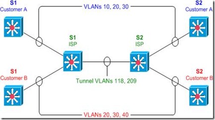
IEEE 802.1Q tunneling can be used to achieve simple layer two VPN connectivity between sites by encapsulating one 802.1Q trunk inside another. The topology below illustrates a common scenario where 802.1Q (or "QinQ") tunneling can be very useful.

clip_image002

A service provider has infrastructure connecting two sites at layer two, and desires to provide its customers transparent layer two connectivity. A less-than-ideal solution would be to assign each customer a range of VLANs it may use. However, this is very limiting, both in that it removes the customers' flexibility to choose their own VLAN numbers, and there may not be enough VLAN numbers (we can only use a maximum of 4,094 or so) available on large networks.

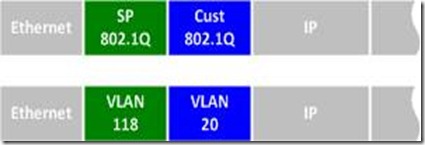
802.1Q tunneling solves both of these issues by assigning each customer a single VLAN number, chosen by the service provider. Within each customer VLAN exists a secondary 802.1Q trunk, which is controlled by the customer. Each customer packet traversing the service provider network is tagged twice: the inner-most 802.1Q header contains the customer-chosen VLAN ID, and the outer-most header contains the VLAN ID assigned to the customer by the service provider.

clip_image004

802.1Q Tunnel Configuration

Before we get started with the configuration, we must verify that all of our switches support the necessary maximum transmission unit (MTU), 1504 bytes. We can use the command show system mtu to check this, and the global configuration command system mtu to modify the device MTU if necessary (note that a reload will be required for the new MTU to take effect).

S1# show system mtu

System MTU size is 1500 bytes

S1# configure terminal

S1(config)# system mtu 1504

Changes to the System MTU will not take effect until the next reload is done.

Next, we'll configure our backbone trunk to carry the top-level VLANs for customers A and B, which have been assigned VLANs 118 and 209, respectively. We configure a normal 802.1Q trunk on both ISP switches. The last configuration line below restricts the trunk to carrying only VLANs 118 and 209; this is an optional step.

S1(config)# interface f0/13

S1(config-if)# switchport trunk encapsulation dot1q

S1(config-if)# switchport mode trunk

S1(config-if)# switchport trunk allowed vlan 118,209

S2(config)# interface f0/13

S2(config-if)# switchport trunk encapsulation dot1q

S2(config-if)# switchport mode trunk

S2(config-if)# switchport trunk allowed vlan 118,209

Now for the interesting bit: the customer-facing interfaces. We assign each interface to the appropriate upper-level (service provider) VLAN, and its operational mode to dot1q-tunnel. We'll also enable Layer two protocol tunneling to transparently carry CDP and other layer two protocols between the CPE devices.

S1(config)# interface f0/1

S1(config-if)# switchport access vlan 118

S1(config-if)# switchport mode dot1q-tunnel

S1(config-if)# l2protocol-tunnel

S1(config-if)# interface f0/3

S1(config-if)# switchport access vlan 209

S1(config-if)# switchport mode dot1q-tunnel

S1(config-if)# l2protocol-tunnel

S2(config)# interface f0/2

S2(config-if)# switchport access vlan 118

S2(config-if)# switchport mode dot1q-tunnel

S2(config-if)# l2protocol-tunnel

S2(config-if)# interface f0/4

S2(config-if)# switchport access vlan 209

S2(config-if)# switchport mode dot1q-tunnel

S2(config-if)# l2protocol-tunnel

We can use the command show dot1q-tunnel on the ISP switches to get a list of all interfaces configured as 802.1Q tunnels:

S1# show dot1q-tunnel

dot1q-tunnel mode LAN Port(s)

-----------------------------

Fa0/1

Fa0/3

Now that our tunnel configurations have been completed, each customer VLAN has transparent end-to-end connectivity between sites. This packet captureshows how customer traffic is double-encapsulated inside two 802.1Q headers along the ISP backbone. Any traffic left untagged by the customer (i.e., traffic in the native VLAN 1) is tagged only once, by the service provider.

Taken From: http://packetlife.net/blog/2010/jul/12/ieee-802-1q-tunneling/

Other:

Saturday, July 14, 2012

How to Get Free Cisco Books (Routers and Switches)

Recently I had a problem with a cisco 2960 switch, to solve it I needed to do a password recovery, so I tried the Ctlr + Break/Pause procedure that I had learned on the CCNA classes, and it didn’t work, so I went online serching for more information an found the following a online book (webpage):

“Catalyst 2960 and 2960-S Switch Software Configuration Guide”

This book has all the cisco 2960 possible commands and configurations for a particular IOS version, and you can download it freely in PDF.

In this book I found that for this particular equipment the recovery was done in a diferent way.

So I went on google and tried searching for other equipments:

Google: Cisco xxxx Software Configuration Guide

and found the same type off manual.

These manuals are a great source of information, in these you can see what the equipment can do, and how to do it, this is especially important if it’s done in a different way from the other equipments.

I highly recommend that you get these for every cisco equipment/IOS that you work with.

Monday, February 20, 2012

GNS3 - PIX Firewall Emulation

PIX Firewall Emulation

GNS3 is also capable of emulating PIX firewalls. Once again, you’ll need to provide your own PIX image. If you want to run more than a restricted license, you’ll also need to have a valid serial number and activation keys.

Configuring Qemuwrapper and Cisco PIX image

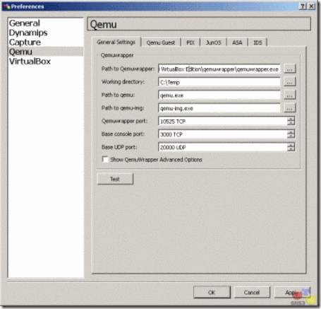
First, go to Preferences on the Edit menu in GNS3. Click on Qemu in the left pane. The default path to the Qemuwrapper should be fine. You may want to specify a different working directory. Note that Qemuwrapper is shipped with a compiled version of Pemu, therefore you do not need Qemu to emulate PIX.

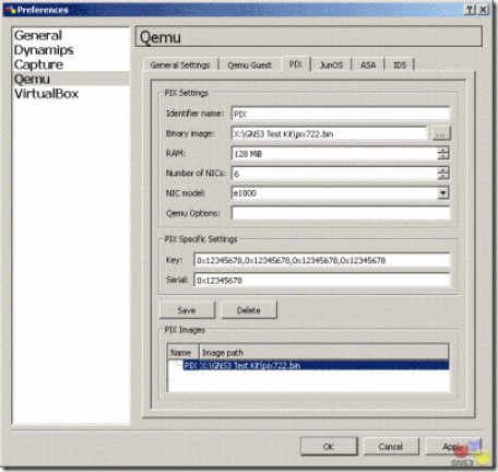
On PIX tab, use the button next to Binary image to specify the location of your PIX operating system image. You may also change other settings like RAM or the number of interfaces. Once you are finished with the settings, click on Save.

clip_image002clip_image004

You may use the default Key and Serial number, if necessary. This will provide a restricted license with limited features. You will need a valid serial number and activation keys to access additional features. The graphic below on the left is a restricted image. Failover, VPN-DES, and VPN-3DES-AES are disabled. You are also limited to 6 physical interfaces and 25 VLANs. The graphic below on the right is unrestricted. With an unrestricted license, these features are enabled along with support for additional interfaces and VLANs.

clip_image006

If you have a serial number and valid activation keys, you may move from a restricted license to an unrestricted license. Type in the activation keys separated by commas with no spaces. Use all lower case. Be sure your serial number is converted to hexadecimal. It is usually in decimal in a show version command. Use a calculator to convert from decimal to hexadecimal if necessary.

Using Cisco PIX

Click OK to return to the GNS3 main interface. Drag a PIX firewall icon from the Nodes Types pane into the workspace. Right-click FW1 and choose Start, then right-click on FW1 again and choose Console.

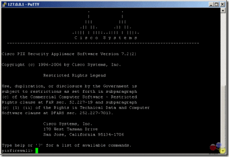
Once you console into your PIX firewall, issue a show version command. If the activation keys do not show up properly, then issue the following command from privileged mode (enable mode):

pixfirewall# activation-key 0x12345678 0x12345678 0x12345678 0x12345678

clip_image008

The command is issued on one line with spaces between the activation keys. Save the configuration using either the write command orcopy run start. Stop the device and restart it. Congratulations! Your PIX firewall is up and running.

Interfaces on the PIX are Ethernet interfaces. To connect to other devices, you’ll need to use either Ethernet or FastEthernet interfaces. You may not connect to a serial interface.

You may connect to other PIX firewalls, routers, and switches. You may not connect to a cloud. Consequently, to connect to a real network or to a Virtual PC, you’ll need to connect from the PIX to a switch, and then from the switch to your Cloud.

CPU usage with PIX

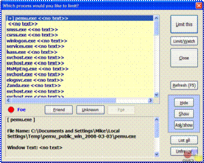
Just as with routers, CPU usage is an issue when emulating PIX firewalls on your computer. You will note that your CPU usage is most likely 100%. There are no idle-pc values available for PIX firewalls at this time. Instead, you may use third-party software to control your CPU usage. There are a variety of products on the market. The one that I use for Windows is called BES and is a free download.

Complete documentation is available on the Web site along with the program download. Once you start your PIX firewall, start BES. Click the Target button. Choose the pemu.exe process and click the Limit this button. A confirmation screen will appear.

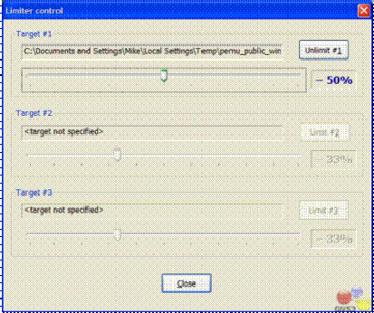
Click the Control button to control how much CPU limiting will be used. I’ve set mine to reduce CPU usage by 50%. If you are running multiple firewalls, you will want to limit each one. This program may also limit other processes running on your Windows computer.

clip_image010clip_image012

For Linux, use cpulimit. You may learn more about cpulimit at the following Web site: http://cpulimit.sf.net. On ubuntu you can use Synaptic Package Manager or Ubuntu Software Centre to download and install cpulimit.

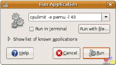
To run cpulimit, press F2 while holding the ALT key down (ALT+F2) in Ubuntu to open a Run Application box. Type the following in the box:

cpulimit –e pemu –l 40

clip_image014

This will limit the application pemu to 40% CPU usage.

Still in your Ubuntu, choose System Monitor under Administration on the System menu. Click the Resources tab. You should see that pemu process is running at 40% of your CPU usage.

Taken From: http://www.gns3.net/gns3-pix-firewall-emulation/

Tuesday, February 14, 2012

Cisco TSHOOT – Top 10 Show Commands

Cisco Router Tips
Top 10 'show' Commands by Tom Lancaster
clip_image002

One of the most important abilities a network administrator can have is the know-how to get information out of his network devices so he can find out what's going on with the network. In most networks, the staple of information gathering has been the "show" commands. Here are my top ten commands to know and love:

  1. show version: Start simple; this command gives uptime, info about your software and hardware and a few other details.
  2. show ip interface brief: This command is great for showing up/down status of your IP interfaces, as well as what the IP address is of each interface. It's mostly useful for displaying critical info about a lot of interfaces on one easy to read page.
  3. show interface: This is the more popular version of the command that shows detailed output of each interface. You'll usually want to specify a single interface or you'll have to hit 'page down' a lot. This command is useful because it shows traffic counters and also detailed info about duplex and other link-specific goodies.
  4. show ip interface: This often overlooked command is great for all the configuration options that are set. These include the switching mode, ACLs, header compression, ICMP redirection, accounting, NAT, policy routing, security level, etc. Basically, this command tells you how the interface is behaving.
  5. show ip route: This indispensable command shows your routing table, which is usually the primary purpose of the box. Get to know the options on this command.
  6. show arp: Can't ping a neighbor? Make sure you're getting an arp entry.
  7. show running-config: This is an easy one. It tells you how the box is configured right now. Also, "show startup-config" will tell you how the router will be configured after the next reboot.
  8. show port: Similar to the show interface command on routers, this command gives you the status of ports on a switch.
  9. show vlan: With the trend toward having lots of VLANs, check this command to make sure your ports are in the VLANs you think they are. Its output is very well designed.
  10. show tech-support: This command is great for collecting a lot of info. It basically runs a whole bunch of other show commands, and spits out dozens of pages of detailed output, designed to be sent to technical support. But, it's also useful for other purposes.

Taken From: http://www.thenetworkadministrator.com/ciscoroutertips.htm

Saturday, December 24, 2011

Backup a Cisco Config Automatically – Time (Kron Method)

In order to get a router to copy the running-config to startup-config, for example every Sunday at 23:00, complete these steps:

1 - Create a kron policy list—This is the script that lists what commands the router should run at the scheduled time.

Router#enable
Router#configure terminal
Router(config)#kron policy-list Backup
Router(config-kron-policy)#cli show startup-config | redirect tftp://192.168.1.252/test.cfg
Router(config-kron-policy)#exit

cli—Specifies EXEC CLI commands within a Command Scheduler policy list.
policy-list—Specifies the policy list associated with a Command Scheduler occurrence.

Note: The reason why write was used rather than copy running-config startup-config is because kron does not support interactive prompts and the copy running-config startup-config command requires interaction. It is important to remember this when you create commands. Also, note that kron does not support configuration commands.


2 - Create a kron occurrence—This informs the router when and how often the policy should run.

Router(config)#kron occurrence SaveConfigSchedule at 23:00 Sun recurring
Router(config-kron-occurrence)#policy-list Backup

SaveConfigSchedule—This is the name of occurrence. Length of occurrence-name is from 1 to 31 characters. If the occurrence-name is new, an occurrence structure will be created. If the occurrence-name is not new, the existing occurrence will be edited.

at—Identifies that the occurrence is to run at a specified calendar date and time.
recurring—Identifies that the occurrence is to run on a recurring basis.


3 - Verify the kron configuration by using the show command.

Router#show kron schedule
Kron Occurrence Schedule
SaveConfigSchedule inactive, will run again in 1 days 12:37:47 at 23:00 on Sun

inactive—Means that kron is not running the command(s) at present.
active—Means that kron is running the current command(s).


Router#show running-configuration
...
kron occurrence SaveConfigSchedule at 23:00 Sun recurring
policy-list Backup
!
kron policy-list Backup
cli show startup-config | redirect tftp://192.168.1.252/test.cfg
...


Note: You can use this to schedule other things, just change the the policy-list, to what you want.

Based Onhttp://www.cisco.com/en/US/products/sw/iosswrel/ps1835/products_tech_note09186a008020260d.shtml

Friday, December 23, 2011

Backup a Cisco Config Automatically – Changes ( Archive Method )

Cisco IOS has the ability to save it’s configuration when you run the write memory command.
Here is how:

R1#enable
R1#configure terminal
R1(config)#archive
R1(config-archive)#path tftp://172.16.10.61/sw3725/sw3725.cfg
R1(config-archive)#write-memory
R1(config-archive)#exit
R1(config)#exit

The “write-memory” option means that when the running-config is saved to the startup-config a copy will also be saved on the tftp server, thus backing up the startup-config every time it’s changed.

In this example, we’ve configured the switch to save to the configuration file to the sw3725 sub-directory of a ttp server.
To test the setup, run the “write memory” command.

R1#enable
R1#write memory

or
R1#copy running-config startup-config

Looking on the sw3725 on the tftp server, we see a configuration file was uploaded:

sw3725.cfg-1

if you save the running-config a couple more times you wil get something like this:

sw3725.cfg-1
sw3725.cfg-2
sw3725.cfg-3

like you see the number at the end of the file name is incremented, every time you save the running-config

Based On: http://www.rainingpackets.com/configuring-cisco-ios-automatically-save-running-configuration-tftp-server-save

More Info at:

Tuesday, November 22, 2011

TDR test in Cisco Devices - Cable Testing

I love finding stuff like this. In the course of my daily Internet browsing, today I came across this post from a while back on the CCNP Recertification blog. It turns out a number of Cisco switches (apparently the 3560/3750, and some 4500 and 6500 modules) have a TDR (Time Domain Reflectometer) embedded in each interface. How cool is that?

Cisco's documentation shows the simple but very handy two-part command syntax.

   Switch# test cable-diagnostics tdr interface g0/1

TDR test started on interface Gi0/1

A TDR test can take a few seconds to run on an interface

Use 'show cable-diagnostics tdr' to read the TDR results.
   Switch# show cable-diagnostics tdr int g0/1


TDR test last run on: March 01 00:09:06

Interface Speed Local pair Pair length Remote pair Pair status
--------- ----- ---------- ------------------ ----------- -----
Gi0/1 auto Pair A 20 +/- 4 meters N/A Open

Pair B 20 +/- 4 meters N/A Open

Pair C 21 +/- 4 meters N/A Open

Pair D 20 +/- 4 meters N/A Open
This output shows a cable approximately 20 meters in length connected to interface G0/1, with nothing attached to the far end. If you're like me, your first thought is "very cool, but is it accurate?" I grabbed a couple spare cables of various lengths and set about an unscientific benchmark. I measured each cable in three manners: by hand, with my Fluke TDR, and with a Catalyst 3560G-24PS-S. My observed results are below.

Cable Length Fluke 3560 ----------------------------------------------

A 69 ft 69 ft 20 +/- 4m (~66 ft)

B 21 ft 21 ft 6 +/- 4m (~20 ft)

C 83 ft 83 ft 25 +/- 4m (~82 ft)

As you can see, the 3560 is impressively accurate, even without its allowed 4m variance. My next consideration was whether a TDR test would disrupt interface operation. Trying it on a live port while running a constant ping yielded no observable effect, not even a brief disconnection pop-up. This is clearly a very handy tool. I only wish Cisco would do more to publicize cool features like this.
Taken From: http://packetlife.net/blog/2008/mar/28/investigating-ciscos-built-in-tdr/

Thursday, May 3, 2007

How to wire Ethernet and Console Cable (Cisco - Roll Over)

Cables form layer 1 of the network — the physical layer. Properly connecting cables is fundamental to healthy network communication. Faulty connections could interrupt service or cause packets to be dropped. Without a clear understanding of cabling, you won’t be able to troubleshoot or design your LAN or WAN. Additionally, knowledge of cable types is important for certification tests like the Cisco CCNA/CCENT.


Cabling basics for network admins

  • Your cable works at layer 1 — Physical of the OSI Model. Also at that layer are the 1’s and 0’s that traverse the cable as an electrical or light signal (depending on what type of cabling you are using).
  • Unshielded twisted pair (UTP) copper cable is used for many functions in network cabling: Ethernet, Serial, ISDN, Console, and more.
  • While you could put different ends on a UTP cable, typically it will have a RJ45 end with 8 pins.
  • With a normal Ethernet cable, the wires run straight through, from one end to the other. Straight-through cables are used to connect a PC to a switch, as in Figure A-1 and Figure A-2. Where each one uses one off the cabling standards, the T568B and T568B
 Figure A-1 - Straight-Through Cable 


Figure A-2 - Straight-Through Cable 

Graphic Courtesy of Cisco Systems
  • With a crossover cable (Figure B), the source and destination of the UTP wires are crossed. This allows you to use it to connect a PC to PC, switch to switch, or router to router.
  • In a crossover cable we use both off the cabling standads, T568A and T568B, one in each end, if one end uses T568B the other uses T568A, and vice-versa.


Figure B - Cross Over Cable 


Graphic Courtesy of Cisco Systems
Now, how is cabling for Cisco routers and switches different?


Cisco console and AUX port cabling
There are a few differences between Cisco cabling and other network device cabling. Two things immediately come to mind:
  • Cisco routers, switches, and firewalls use a special “rolled” cable for console and auxiliary port access.
  • Cisco offers intelligent serial cabling.
One of the most confusing things to Cisco newcomers is the concept of the console cable. Other SMB and home-networking devices don’t usually have a console port. With those devices, they receive a DHCP IP address and then you can configure them over the network from there. With Cisco devices, there is no IP address on the device, and you must first use the console port and console cable to configure the router, switch, or firewall OOB (out of band).
The Cisco console cable is a special cable. It isn’t wired like an Ethernet cable. However, if you didn’t have a console cable, you could cut off the end of a straight-through Ethernet cable, change the pin out, and recrimp it to make it a console cable.
Below, you can see the pin out of a console cable. The console cable is a “rolled” cable, because if you look at the pins from one end to the other, it is as if the end was rolled over (the order is flipped), as in Figure C.

Figure C - Console Cable (Rolled Cable)

Graphic Courtesy of Cisco Systems
Traditionally Cisco console cables were RJ45-RJ45 and then you would use a RJ45-DB9 adaptor to connect it to your PC’s serial port (COM port). Today, new Cisco devices come with console cables that have a DB9 adaptor integrated/molded to the cable on one end (Figure D). Keep in mind that the data moving across the console cable is serial data (not Ethernet).

Figure D - RJ45-DB9 adaptor


Graphic Courtesy of Cisco Systems
For those equipements tha don't have an integrated DB9 ports, here how you can make your own DB9 adapter:


Click on the images to enlarge
While what I said above concerning console cables is true for most Cisco devices, there are variations on the console cable. For more detailed information about Cisco console and AUX port cabling (including the pin-out for a console cable so that you can make your own), see this Cisco document Cisco Cabling Guide for Console and AUX Ports.

David Davis has worked in the IT industry for 15+ years and holds several certifications, including CCIE, CCNA, CCNP, MCSE, CISSP, VCP. He has authored hundreds of articles and numerous IT training videos. Today, David is the Director of Infrastructure at Train Signal.com. Train Signal, Inc. is the global leader in video training for IT Professionals and end users.

Taken From: http://blogs.techrepublic.com.com/networking/?p=649
and added some stuff about the cabling standards (like here)


Another good reference for building ethernet cables is:
http://www.ertyu.org/steven_nikkel/ethernetcables.html