Make your own Power Over Ethernet Injector set for $2 in Parts
Ever need to install a network hub, camera, or other device in a location that did not have a locally available power outlet? Need to ‘extend’ the power cord?
In this tutorial, we’ll be building a very cheap Power Over Ethernet Injector out of $2 in parts. This will let you place your power supply for your device near the ethernet hub, where power is plentiful, and place the device itself hundreds of feet away.
Caveat: There is a Power Over Ethernet (POE) standard, which we’re ignoring, as this particular injector setup is for legacy products that do not offer POE support.
The standart states the minumum power supply should be:
- 44V DC / 350mA = 15.4 Watts
so for standart compatibility (802.3af - PSE Mid-Span) you would have to use a 48V DC power supply with equal or more than 350mA.
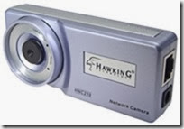
In my case, I’m making it for my wired network camera, a Hawking HNC-210, which is generally alwayssituated farther away from the power outlet. It comes with a fairly short (6′) power cable, which is an odd product design consideration. Since you’d generally put a camera at eye-level or higher, this cable is really too short for most installs.
Parts List: $1.80 US:
- 1. RJ-45 pass-thru connector 80¢
- 2. 2.1mm power jack and plug 50¢
- 3. spare (short) working ethernet cable 50¢
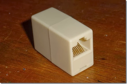
The first item we need is an ethernet (RJ-45) pass-thru connector, for patching 2 ethernet cables end to end. It is available at many local retailers/computer shops. I grabbed a few at BG Micro for 80¢ a piece. The nice thing about these is you’re getting 2 pre-wired RJ-45 connectors for very cheap.
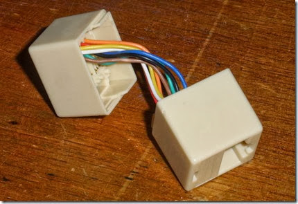
A bit of man-handling to pry the two halves apart, and we have 2 halves of our POE injector. Simply cut all 8 wires at the half way point. You can tell which wire goes to which pin by looking at the inside of the now disassembled connector. Take notes of which wire goes to which pin, using a regular ethernet cable as a reference. There are 8 wires, which we need to be grouped. 4 wires are for ethernet, 2 wires for Positive Power, and 2 wires for Negative Power (Ground).
You’ll need to strip and tin all the ends of each tiny wire on both pieces. We’re basically hand-wiring connections for power and ethernet in each connector. Use the wiring table later in this article to make the connections. While you’re here, why not put some shrink tubing over each wire to protect them from cross-connection later.
I need more Power, Scotty!
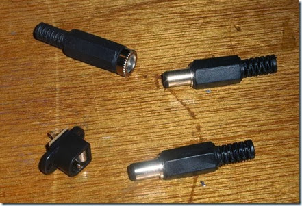
Next up in the arsenal, we need the power jacks to pass the power from the AC wall wart to the camera. I checked the camera, and it used a standard 2.1mm power jack. I picked up 2 example jacks from an electronics supplier.
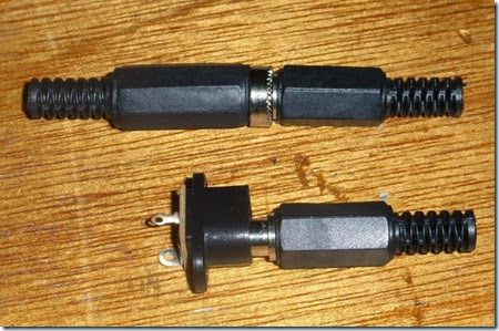
The top set is an inline jack and plug, which costs $1.20 for the set. The bottom set is an panel mount jack and plug, which costs considerably less, at only 50¢ for the set. First, check to make sure they work together.
I soldered 2 wires to the power plug that were equal length to the ethernet dongle I already had on hand. I slipped some shrink tubing over it, then made the connections.
With the Power Connections, polarity doesn’t matter as much as making sure you don’t flip the circuit with your cable build. If you decide blue is tip and brown is ground, stick with it at both ends of the injectors – not following this is a sure way of destroying the device you’re powering.
In my case, I connected the tip of the power plug to BOTH the 2 blue wires, and the shield to BOTH the 2 brown wires. On the other side, I connected the same to the tiny panel-mount power jack. I then used hot-melt glue to mount the panel mount to the remaining plastic frame.
Why connect to both wires? In case one wire fails in a regular ethernet cable, it’ll still work. Plus, there is less voltage loss with the larger combined wire. The total voltage loss is negligible for most installs. If you find your device isn’t working properly, check to see if the cable is too long, and the voltage is too low to power the device.
Next up the complex ethernet wiring….
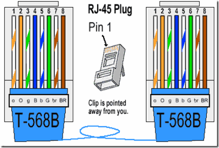
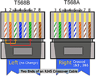
Common straight-through ethernet cables only use 4 wires out of the 8 inside the sheathing. The common wiring in illustrated below.
Take your short working ethernet cord and cut it in half. You’ll want 2 short 8″ pieces, with the working ethernet RJ-45 ends still attached. Strip off an inch at the cut end, and expose the 8 wires inside. Cut the blue and brown sets of wires off. These are unused in this application – these ‘dongles’ will be the ethernet in and out connections.
So the ethernet wires (in most cases, you should check) that we’ll be using to pass the ethernet traffic is the 2 orange wires and the 2 green wires, which fall on pins 1, 2, 3 and 6. Simply connect the pin 1 on the ethernet dongle to pin 1 on the ethernet connector jack, and so on through the other 7 wires on both sides.
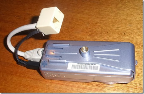
Finished Power Over Ethernet Injector and Splitter
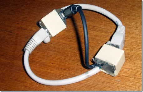
I covered open connections with shrink tubing, then tucked all wires inside the tiny connector cases. I then used hot-melt glue to seal up the open ends of the connectors, and now I have a matched pair of Power Over Ethernet Injectors!
Installed at the Camera End
Simply attach one end of your 100+ foot long ethernet cable to this end, place your camera anywhere, with only one cable feeding to it.
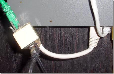
Installed at Hub/Switch End
At the other end, at the switch/hub (also suitably close to a power outlet), simply plug it into an available port, plug in the power supply, then the camera feed line.
Shield your eyes! Cable Porn! Shocking double-69 cable-on-cable action!
Based On: http://underdesign.wordpress.com/2010/04/07/make-your-own-power-over-ethernet-injector/
PoE Standart Details: http://www.ieee.li/pdf/viewgraphs/introduction_to_poe_ieee802.3af_802.3at.pdf
