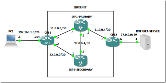
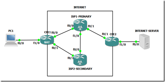
In the past I had the need to implement failover between two connections to the Internet on the same router, at the time I implemented it using EEM Scripts which wasn’t the most elegant solution, so here I’m going to show you a a better solution to do this.
Implementing the failover mechanism at first glance seems easier with one router than with two, but that is not the case, with two routers you can have them configured normally with the adition of VRRP/HSRP to do the failover between the routers.
With only one router you are going to have two aditional problems:
- Changing the route from the primary to the secondary Internet access
- Changing the NAT overload to the Interface towards the Secondary ISP / WAN (this was the part that I implemented with EEM scripts)
the first you can easily solve with a floating static route (secondary route) and a track / ip sla (to remove the primary route when the connectivity to the primary ISP is lost).
The second one is harder, you can have two NAT rules with two interfaces towards the two ISPs:
ip nat inside source 130 interface FastEthernet0/0 overloadip nat inside source 131 interface FastEthernet1/0 overload
but selecting the one as the active one is the tricky part.
Even if the interface towards the primary ISP were to fail and become shutdown, the NAT rule remains active.
The cenario bellow has two different ISPs for for the WAN accesses, but its the sames as having two different connectivities via the same ISP (eg. Primary via Fiber Optic | Secondary via 4G)
Cenario
Logical View
Fisical View
You can download the lab fully implemented here:
it was implemented on GNS3 v1.2.1.
Configuration
PC1
====================================================
enable
conf t
hostname PC1
interface FastEthernet0/0
description *** Link to CPE1 ***
ip address 192.168.1.1 255.255.255.0
no shutdown
ip route 0.0.0.0 0.0.0.0 192.168.1.254 name DefaultGW
do write
CPE1
====================================================
enable
conf t
hostname CPE1
interface FastEthernet0/0
description *** Link to ISP1 ***
ip address 11.0.0.2 255.255.255.252
ip nat outside
no shutdown
interface FastEthernet0/1
description *** Link to ISP2 ***
ip address 22.0.0.2 255.255.255.252
ip nat outside
no shutdown
interface FastEthernet1/0
no switchport
description *** Link to PC1 ***
ip address 192.168.1.254 255.255.255.0
ip nat inside
no shutdown
!-- Select the Route - via ISP1 or ISP2 -------------------
!!!!!!!!!!!!!!!!!!!!!!!!!!!!!!!!!!!!!!!!!!!!!!!!!!!!!!!!!!!!!!!!!!!!!!!!!!!!!!!!!!!!!!!!!!!!!!!!
! The first route makes all the traffic flow via
! ISP1, but this is conditioned to track 10, that
! detects the connectivity to ISP1.
! If track 10 fails the route is removed from the
! routing table.
!
!
! The second route has an higher administrative
! distance (worst), and as long as the first rule
! is available this rule is never inserted on
! the routing table (aka floating static route)
!
! If the first route disapears because the track
! failed then the second route is inserted in the
! routing table, and all traffic will flow via ISP2
!!!!!!!!!!!!!!!!!!!!!!!!!!!!!!!!!!!!!!!!!!!!!!!!!!!!!!!!!!!!!!!!!!!!!!!!!!!!!!!!!!!!!!!!!!!!!!!!
ip route 0.0.0.0 0.0.0.0 11.0.0.1 track 10 name Default-Primary
ip route 0.0.0.0 0.0.0.0 22.0.0.1 250 name Default-Secondary
ip sla 10
icmp-echo 11.0.0.1 source-interface FastEthernet0/0
frequency 5
ip sla schedule 10 life forever start-time now
track 10 ip sla 10 reachability
!show track brief
!show track 10
!-- Change the NAT Interface to Reflect the Active Route --
!!!!!!!!!!!!!!!!!!!!!!!!!!!!!!!!!!!!!!!!!!!!!!!!!!!!!!!!!!!!!!!!!!!!!!!!!!!!!!!!!!!!!!!!!!!!!!!!
! Changing the routes isn't enough, we also
! need to change the NAT rule, because each route
! implies a different exit interface.
!
! To select which NAT rule will be used for each
! route, we used route maps instead of an ACL
! to identify traffic (active the rule).
!
! These route maps match the LAN traffic, plus
! the current next hop to forward the traffic thus
! selecting the correct NAT rule for the current
! active route.
!!!!!!!!!!!!!!!!!!!!!!!!!!!!!!!!!!!!!!!!!!!!!!!!!!!!!!!!!!!!!!!!!!!!!!!!!!!!!!!!!!!!!!!!!!!!!!!!
ip nat inside source route-map RM-ISP1-PRIMARY interface FastEthernet0/0 overload
ip nat inside source route-map RM-ISP2-PRIMARY interface FastEthernet0/1 overload
access-list 130 remark *** Traffic for The Internet (NAT) ***
access-list 130 permit ip 192.168.1.0 0.0.0.255 any
route-map RM-ISP1-PRIMARY permit 10
match ip address 130
match interface FastEthernet0/0 !--> Match the exit interface of the route
route-map RM-ISP2-PRIMARY permit 10
match ip address 130
match interface FastEthernet0/1 !--> Match the exit interface of the route
!show route-map
!-- Simulate a Failure Along The Way ----------------------
!!!!!!!!!!!!!!!!!!!!!!!!!!!!!!!!!!!!!!!!!!!!!!!!!!!!!!!!!!!!!!!!!!!!!!!!!!!!!!!!!!!!!!!!!!!!!!!!
! To simulate the failure to see the topology
! changing to the secondary access, we are going
! to use a route to force the track/ip sla to fail.
!
! This route will force all the connectivity test
! traffic destined for ISP1(11.0.0.1) to go to NULL
! which is a black hole. Like this ISP1 will never
! get the icmp echos requests from the ip sla test
! or respond to it, thus simulating a connectivity
! failure towards ISP1
!
! NOTE: It takes a couple of seconds to change
!!!!!!!!!!!!!!!!!!!!!!!!!!!!!!!!!!!!!!!!!!!!!!!!!!!!!!!!!!!!!!!!!!!!!!!!!!!!!!!!!!!!!!!!!!!!!!!!
!-- Failure Sim + Debug/Tshoot --
do debug ip nat
ping 77.0.0.1
show ip route
!S* 0.0.0.0/0 [1/0] via 11.0.0.1
ip route 11.0.0.1 255.255.255.255 NULL0 name FailureSim
ping 77.0.0.1
show ip route
!S* 0.0.0.0/0 [250/0] via 22.0.0.1
! Both Pings will work but notice that the default
! route is diferent (diferent next hop)
!-- Restore to Normal Operation --
no ip route 11.0.0.1 255.255.255.255 NULL0 name FailureSim
do no debug all
ISP1-PRIMARY
====================================================
enable
conf t
hostname ISP1-PRIMARY
interface FastEthernet0/0
description *** Link to CPE1 ***
ip address 11.0.0.1 255.255.255.252
no shutdown
interface FastEthernet0/1
description *** Link to CPE2 ***
ip address 11.0.0.5 255.255.255.252
no shutdown
interface FastEthernet1/0
no switchport
description *** Link to ISP2 ***
ip address 22.0.0.6 255.255.255.252
no shutdown
ip route 77.0.0.0 255.255.255.248 11.0.0.6 name PublicIPs
ip route 22.0.0.0 255.255.255.252 22.0.0.5 name NatedLAN-viaIPS2
do write
ISP2-SECONDARY
====================================================
enable
conf t
hostname ISP2-SECONDARY
interface FastEthernet0/1
description *** Link to CPE1 ***
ip address 22.0.0.1 255.255.255.252
no shutdown
interface FastEthernet0/0
description *** Link to ISP1 ***
ip address 22.0.0.5 255.255.255.252
no shutdown
ip route 0.0.0.0 0.0.0.0 22.0.0.6 name Default
do write
CPE2
====================================================
enable
conf t
hostname CPE2
interface FastEthernet0/1
description *** Link to ISP1 ***
ip address 11.0.0.6 255.255.255.248
no shutdown
interface FastEthernet1/0
description *** Link to Internet Server ***
no switchport
ip address 77.0.0.6 255.255.255.248
ip route 0.0.0.0 0.0.0.0 11.0.0.5 name Default
do write
INTERNET SERVER
====================================================
enable
conf t
hostname INTERNET-SERVER
interface FastEthernet0/0
description *** Link to CPE1 ***
ip address 77.0.0.1 255.255.255.248
no shutdown
ip route 0.0.0.0 0.0.0.0 77.0.0.6 name Default
do write


3 comments:
IMPRESSED WITH SUCH A GOOD CONTENT!!
VERY INTERESTING
GREAT WORK
Fiber optic network cabling
fiber optic solutions in dubai
great post , thank u for your blog visit us fiber optic solutions in dubai
Fiber optic network cabling
THANKS FOR SHARING SUCH A AMAZING WORK
GREAT PIECE OF WORK!!!
structured cabling companies in dubai
Post a Comment