Spanning Tree Protocol, Rapid STP Port Costs - Port States
Written by Arani Mukherjee. Posted in Spanning Tree Protocol (STP)
Spanning Tree Protocol, Rapid STP port costs and port states are an essential part of the STP algorithm that affect how STP decides to forward or block a port leading to the Root Bridge.
In our previous article that covers Understand STP Principles, Redundant Network Links & Broadcast Storms we encountered some key issues related to switching that causes degradation in network performance.
Those issues were broadly categorised as follows:
· Broadcast storm
· Unstable MAC Table in switches
· Multiple duplicate frames arriving at hosts
In order to avoid the above situations, Spanning Tree Protocol or STP is implemented. The aim of this protocol and its deployment is to provide a single path of communication between each Ethernet segment (e.g a link between two switches). Since the issues discussed in our previous article, and STP itself only relates to switching, our discussion will only refer to switches. It is worth noting that both bridges and switches make use of the STP protocol.
To create a single path between each Ethernet segment, for to and fro communication, STP decides on the state of each Ethernet interface. An interface can only be in two states, Forwarding state or Blocking state. STP employs its algorithm and puts certain interfaces in a Forwarding state. All other interfaces not put in a forwarding state are placed in a Blocking state.
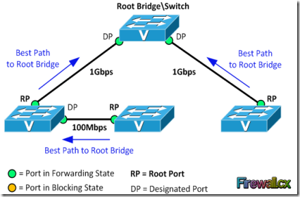
Now before we start looking into what criteria STP uses to put a port in Forwarding or Blocking state, let’s understand certain terminologies using the network diagram below:
Root Bridge: A switch with all its ports placed in Forwarding state is a root bridge. The Root Bridge is often called Root Switch.
Another way to think of the Root Bridge is as the Master Switch (for loop avoidance matters), for which only one active path must exist from all other switches, effectively avoiding any possible network loops.
Root Port: For a non–root switch, the port that connects this switch to the root switch, with the least cost, is called the root port.
Designated Port: A non – root port, which is forwarding away from the root switch, and has the lowest cost in that Ethernet segment, is called the designated port.
Cost: A port cost is defined by the speed at which the port operates. The cost of a port is inversely related to the associated bandwidth and therefore a port with a low cost value (greater bandwidth-speed) is more preferable than a port with high cost value (lower bandwidth-speed).
Note: The process of the Root Bridge election, Designated and Root Ports is covered in great detail in our Spanning Tree Protocol: Bridge ID, Priority, System ID Extension & Root Bridge Election Process articles.
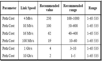
The table below was published by the IEEE group in 1998 and represented the cost against bandwidth:
The original STP Cost-Bandwidth table - Year 1998
The cost value (column marked “Range”) supported a 16-bit value (1 – 65535) while the root path cost was assigned a 32bit value embedded within the Bridge Protocol Data Unit (BPDU) field. BPDU's are special STP packets that contain all necessary information about the network's Spanning Tree topology.
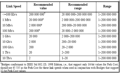
In 2004, the revised 802.1D had its 16- bit path cost increased to a 32-bit value, providing more granularity:
STP uses the following criteria to decide whether to place a port in a Forwarding state or Blocking state
1. STP elects a Root Bridge, and then puts all its working interfaces in a Forwarding state
2. All other switches are now non–root switches. STP now looks at all the Root Ports from these switches, and finds the one with the Least Cost. Once this is found, STP places that interface in a Forwarding state.
3. Now STP finds all the Designated ports on the non–root switches, and places them in a Forwarding state.
4. Then STP places all other ports in a Blocking state.
It is absolutely essential to understand that the process of the Root Bridge and non-root switches election along with the port selection is performed only on working interfaces. Any failed/down interface i.e. no cables connected, or an interface which has been shutdown administratively, is parked into an STP Disabled state. Such ports are not considered during STP algorithm deployment.
Now let’s summarise what has been established previously:
| Port Description | STP State | Important Observation |
| All ports on root switch | Forwarding | Root switch is always the designation switch on all Ethernet segment |
| Root ports on non – root switches | Forwarding | These are the ports that non – root switches use to reach the root switch |
| Every LAN’s designation port | Forwarding | The non – root port, that forwards away from the root switch, with lowest cost |
| All other working ports | Blocking | These ports are not used for forwarding, and any frames received on these interfaces are not forwarded as well. |
The following table shows the available Port states for the original STP (802.1D) and newer Rapid STP (802.1w) designed to provide faster convergenceto topology changes. We should note that the three states Disabled, Blocking & Listening from STP (802.1D) have merged into one state, Discarding, for Rapid STP (802.1w):
| STP (802.1D) Port State | RSTP (802.1w) Port State | Is Port Included in Active Topology? | Is Port Learning MAC Addresses? |
| Disabled | Discarding | No | No |
| Blocking | Discarding | No | No |
| Listening | Discarding | Yes | No |
| Learning | Learning | Yes | Yes |
| Forwarding | Forwarding | Yes | Yes |
Support of Rapid STP (RSTP) in Cisco Catalyst Switches
This table shows the support of RSTP in Cisco Catalyst switches, and the minimum software required for that support. As a general rule of thumb, all newer Catalyst switches provide support for RTSP.
| Catalyst Platform | MST w/ RSTP | RPVST+ (also known as PVRST+) |
| Catalyst 2900 XL / 3500 XL | Not available. | Not available. |
| Catalyst 2940 | 12.1(20)EA2 | 12.1(20)EA2 |
| Catalyst 2950/2955/3550 | 12.1(9)EA1 | 12.1(13)EA1 |
| Catalyst 2970/3750 | 12.1(14)EA1 | 12.1(14)EA1 |
| Catalyst 3560 | 12.1(19)EA1 | 12.1(19)EA1 |
| Catalyst 3750 Metro | 12.1(14)AX | 12.1(14)AX |
| Catalyst 2948G-L3/4908G-L3 | Not available. | Not available. |
| Catalyst 4000/2948G/2980G (CatOS) | 7.1 | 7.5 |
| Catalyst 4000/4500 (IOS) | 12.1(12c)EW | 12.1(19)EW |
| Catalyst 5000/5500 | Not available. | Not available. |
| Catalyst 6000/6500 | 7.1 | 7.5 |
| Catalyst 6000/6500 (IOS) | 12.1(11b)EX, 12.1(13)E, 12.2(14)SX | 12.1(13)E |
| Catalyst 8500 | Not available. | Not available. |
In this article we covered Spanning Tree Protocol, Rapid STP port costs and port states. In our next article, we will start looking at how STP deploys the criteria. So, we will understand how STP decides which switch will be the Root Bridge , how it elects the Root Ports and Designated Ports. We will also investigate how STP reacts to any changes to the network topology and incorporates the changes in its algorithm.


1 comment:
good blog...
structured cabling companies
structured cabling solutions
Post a Comment