Sunday, October 28, 2012

Shrink Your Arduino Projects (ATtiny)

Ever since I started making projects with the Arduino, I’ve had a desire to shrink them down to a single, small circuit board. One of my first projects, a customizable SLR intervalometer, was packed in a phonebook-sized cardboard box and used the Arduino Deumilanove connected to a breadboard with jumper wires. I brought the box out to Central Park at 5am to make a timelapse of the sunrise, but when I got to the park, I spent 20 minutes fixing the connections between the Arduino, the breadboard, and the components. Since then, I’ve explored a few different ways of shrinking projects down and making them more robust. For the intervalometer, I designed a circuit board that had female header pins to seat an Arduino Nano. It was a huge improvement on the design, but I knew I could do a lot better.

I tried to teach myself AVR programming, but ran into a lot of snags along the way. By the time I got an LED to blink, I had invested hours in the project (a stark contrast to my first Arduino experience) and was feeling quite discouraged. I also tried using PICAXE chips. While it was much easier to get started with these chips than with AVR programming, I felt like I was abandoning all my years of C programming to learn a form of BASIC that’s an entirely different animal from when I used it as a kid.

Blinking an LED with an ATTiny Chip
When I came across the Programming an ATtiny w/ Arduino Tutorial below, I was elated. They walk you through the process of using the Arduino IDE and programming language to program 8 pin ATtiny45 or ATtiny85 chips. Not only that, but they also walk you through using an Arduino board to act as the programmer, or ISP. I had everything I needed, except for the chips, so I eagerly awaited my rush shipment of ATtinies.

I followed the tutorial and found that it was actually rather easy to program these little chips using the Arduino code and IDE. I tried out the basic digital and analog I/O functions and they all worked as expected. I did a little experimentation with a few other functions with some success, so your milage may vary. To test it all out, I even made a cute little blinky toy within about an hour. I’m now thinking about revisiting my intervalometer project and shrinking it down from a cardboard box to a mini Altoids tin!

Watch the video here

Programming an ATtiny w/ Arduino Tutorial

This tutorial shows you how to program an ATtiny45 or ATtiny85 microcontroller using the Arduino software and hardware. The ATtiny45 and ATtiny85 are small (8-leg), cheap ($2-3) microcontrollers that are convenient for running simple programs.

This tutorial is obsolete! See the updated version of this tutorial (with support for Arduino 1.0).

They are almost identical, except that the ATtiny85 has twice the memory of the ATtiny45 and can therefore hold more complex programs. We like to use both of them with paper circuits and other craft electronics. To program them, we’ll use a port of the Arduino core libraries created by Alessandro Saporetti and slightly modified by HLT.

Materials and Tools

For this tutorial, you’ll need:

  • Arduino Uno or Duemilanove (w/ an ATmega328, not an older board with an ATmega168)
  • ATtiny45 or ATtiny85 (8-pin DIP package)
  • a 10 uF capacitor (e.g. from Sparkfun or from Digi-Key)
  • a breadboard
  • jumper wires
  • For more information, see our list of materials and parts and our list of prototyping supplies.

    Software

    You’ll need the Arduino software (version 0022) and a plugin to add support for the ATtiny45/85. Installation instructions for the Arduino software are available for Windows and for Mac OS X.

    Download: Arduino software, attiny45_85.zip

    The ATtiny45 / ATtiny85 Microcontroller

    Here’s the pinout of the ATtiny45 and ATtiny85:

    clip_image002

    Installing ATtiny45 / ATtiny85 support in Arduino

    · Download: attiny45_85.zip

    · Locate your Arduino sketchbook folder (you can find its location in the preferences dialog in the Arduino software)

    · Create a new sub-folder called “hardware” in the sketchbook folder.

    · Copy the attiny45_85 folder from the attiny45_85.zip to the hardware folder.

    · Restart the Arduino development environment.

    Turning the Arduino board into a programmer

    We’re going to use the Arduino board to program the ATtiny45 or ATtiny85. First,
    we’ll need to turn the Arduino board into an “in-system programmer” (ISP). To this:

  • Run the Arduino development environment.
  • Open the ArduinoISP sketch from the examples menu.
  • Select the board and serial port that correspond to your Arduino board.
  • Upload the ArduinoISP sketch.
  • Connecting the Arduino board and the ATtiny

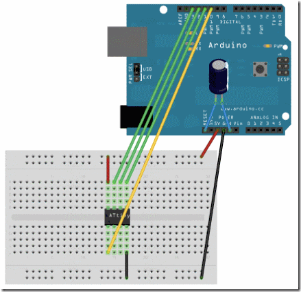
    We’ll connect the Arduino board to the ATtiny as shown in the following diagram. Use the dot in the corner of the ATtiny to orient it properly. We’ll also connect a 10 uF capacitor between reset and ground on the Arduino board as shown in the diagram (the stripe on the capacitor that’s marked with a negative sign (-) should go to ground). The capacitor prevents the Arduino board from resetting (which starts the bootloader), thus ensuring that the Arduino IDE talks to the ArduinoISP (not the bootloader) during the upload of sketches. (The capacitor is needed if you’re using an Arduino Uno, and might also be necessary for an Arduino Duemilanove.)

    clip_image004

    Pin connections:

  • ATtiny Pin 2 to Arduino Pin 13 (or SCK of another programmer)
  • ATtiny Pin 1 to Arduino Pin 12 (or MISO of another programmer)
  • ATtiny Pin 0 to Arduino Pin 11 (or MOSI of another programmer)
  • ATtiny Reset Pin to Arduino Pin 10 (or RESET of another programmer)
  • Programming the ATtiny45 or ATtiny85

    Next, we can use the Arduino as an ISP to upload a program to the ATtiny45/85:

  • Open the Blink sketch from the examples menu.
  • Change the pin numbers from 13 to 0.
  • Select “ATtiny45 (w/ Arduino as ISP)” or “ATtiny85 (w/ Arduino as ISP)” from the Tools > Board menu (leave the serial port set to that of your Arduino board).
  • Upload the sketch.
  • You’ll probably get the following message, but don’t worry, the upload should have worked anyway:
  • avrdude: please define PAGEL and BS2 signals in the configuration file for part ATtiny85


    avrdude: please define PAGEL and BS2 signals in the configuration file for part ATtiny85


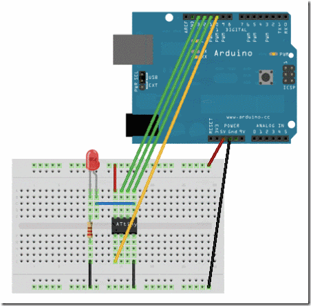
    Now, connect an LED and see if it blinks.
    clip_image006


    Reference


    The following Arduino commands should be supported:


    Taken From:


    http://blog.makezine.com/2011/10/10/how-to-shrinkify-your-arduino-projects/


    http://hlt.media.mit.edu/?p=1229

    Sunday, October 21, 2012

    Cisco Vlan Tunneling (Double Tagging / QinQ)

    IEEE 802.1Q Tunneling

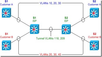
    IEEE 802.1Q tunneling can be used to achieve simple layer two VPN connectivity between sites by encapsulating one 802.1Q trunk inside another. The topology below illustrates a common scenario where 802.1Q (or "QinQ") tunneling can be very useful.

    clip_image002

    A service provider has infrastructure connecting two sites at layer two, and desires to provide its customers transparent layer two connectivity. A less-than-ideal solution would be to assign each customer a range of VLANs it may use. However, this is very limiting, both in that it removes the customers' flexibility to choose their own VLAN numbers, and there may not be enough VLAN numbers (we can only use a maximum of 4,094 or so) available on large networks.

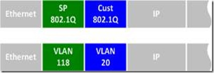
    802.1Q tunneling solves both of these issues by assigning each customer a single VLAN number, chosen by the service provider. Within each customer VLAN exists a secondary 802.1Q trunk, which is controlled by the customer. Each customer packet traversing the service provider network is tagged twice: the inner-most 802.1Q header contains the customer-chosen VLAN ID, and the outer-most header contains the VLAN ID assigned to the customer by the service provider.

    clip_image004

    802.1Q Tunnel Configuration

    Before we get started with the configuration, we must verify that all of our switches support the necessary maximum transmission unit (MTU), 1504 bytes. We can use the command show system mtu to check this, and the global configuration command system mtu to modify the device MTU if necessary (note that a reload will be required for the new MTU to take effect).

    S1# show system mtu

    System MTU size is 1500 bytes

    S1# configure terminal

    S1(config)# system mtu 1504

    Changes to the System MTU will not take effect until the next reload is done.

    Next, we'll configure our backbone trunk to carry the top-level VLANs for customers A and B, which have been assigned VLANs 118 and 209, respectively. We configure a normal 802.1Q trunk on both ISP switches. The last configuration line below restricts the trunk to carrying only VLANs 118 and 209; this is an optional step.

    S1(config)# interface f0/13

    S1(config-if)# switchport trunk encapsulation dot1q

    S1(config-if)# switchport mode trunk

    S1(config-if)# switchport trunk allowed vlan 118,209

    S2(config)# interface f0/13

    S2(config-if)# switchport trunk encapsulation dot1q

    S2(config-if)# switchport mode trunk

    S2(config-if)# switchport trunk allowed vlan 118,209

    Now for the interesting bit: the customer-facing interfaces. We assign each interface to the appropriate upper-level (service provider) VLAN, and its operational mode to dot1q-tunnel. We'll also enable Layer two protocol tunneling to transparently carry CDP and other layer two protocols between the CPE devices.

    S1(config)# interface f0/1

    S1(config-if)# switchport access vlan 118

    S1(config-if)# switchport mode dot1q-tunnel

    S1(config-if)# l2protocol-tunnel

    S1(config-if)# interface f0/3

    S1(config-if)# switchport access vlan 209

    S1(config-if)# switchport mode dot1q-tunnel

    S1(config-if)# l2protocol-tunnel

    S2(config)# interface f0/2

    S2(config-if)# switchport access vlan 118

    S2(config-if)# switchport mode dot1q-tunnel

    S2(config-if)# l2protocol-tunnel

    S2(config-if)# interface f0/4

    S2(config-if)# switchport access vlan 209

    S2(config-if)# switchport mode dot1q-tunnel

    S2(config-if)# l2protocol-tunnel

    We can use the command show dot1q-tunnel on the ISP switches to get a list of all interfaces configured as 802.1Q tunnels:

    S1# show dot1q-tunnel

    dot1q-tunnel mode LAN Port(s)

    -----------------------------

    Fa0/1

    Fa0/3

    Now that our tunnel configurations have been completed, each customer VLAN has transparent end-to-end connectivity between sites. This packet captureshows how customer traffic is double-encapsulated inside two 802.1Q headers along the ISP backbone. Any traffic left untagged by the customer (i.e., traffic in the native VLAN 1) is tagged only once, by the service provider.

    Taken From: http://packetlife.net/blog/2010/jul/12/ieee-802-1q-tunneling/

    Other:

    Friday, October 5, 2012

    Wifi on Linux via Command Line

    Connect to a wireless network via command line


    I know, the first thing you are asking is “Why would I want to have to connect to a wireless network from the command line?” To that question I can give you a simple answer…What if you want to create a script to run that will bring up your wireless network as soon as your desktop is loaded? You could get really complex and create a start up script to load a desktop based on what wirelessaccess point you needed to join. That’s one of the beauties of Linux, if you can dream it, you can do it.
    But I am getting too far ahead of myself. Let’s get back to the basics shall we? First I am going to assume that your wireless card was detected by your distribution and has the proper drivers loaded. With that accomplished you will need to have the following tools:
    • ifconfig: Enable your wireless device.
    • iwlist: List the available wireless access points.
    • iwconfig: Configure your wireless connection.
    • dhclient: Get your IP address via dhcp.
    The first command you need to use is ifconfig. With this command you are going to enable your wireless device. Most likely your device will be called wlan0. So in order to enable this you would enter the command (as root):

    ifconfig wlan0 up

    You won’t see any feedback unless there is a problem.
    The next step is to scan for your wireless network to make sure it is available. Do this with the following command:

    iwlist wlan0 scan

    With this command you will see output like the following:

    Cell 01 - Address: 00:21:43:4E:9B:F0
    ESSID:"HAIR STROBEL"
    Mode:Master
    Channel:5
    Frequency:2.432 GHz (Channel 5)
    Quality=100/100? Signal level:-45 dBm? Noise level=-95 dBm
    Encryption key:on
    IE: WPA Version 1
    Group Cipher : TKIP
    Pairwise Ciphers (1) : TKIP
    Authentication Suites (1) : PSK
    IE: IEEE 802.11i/WPA2 Version 1
    Group Cipher : TKIP
    Pairwise Ciphers (1) : CCMP
    Authentication Suites (1) : PSK
    Bit Rates:1 Mb/s; 2 Mb/s; 5.5 Mb/s; 11 Mb/s; 22 Mb/s
    6 Mb/s; 9 Mb/s; 12 Mb/s; 18 Mb/s; 24 Mb/s
    36 Mb/s; 48 Mb/s; 54 Mb/s
    Extra:tsf=000002f1d9be01b7

    So you know this network is available. From the above output you can also see this network is employing WPA2, so you will need a passkey. If you don’t know that passkey, you are out of luck (which would be the case no matter if you were using a front end in Linux, Windows, or Mac.)

    Now it’s time to configure your connection. To do this issue the command:

    iwconfig wlan0 essid NETWORK_ID key WIRELESS_KEY

    Where NETWORK_ID is the ESSID of the network with which you want to connect and WIRELESS_KEY is the security key needed to connect to the wireless access point.

    Note: iwconfig defaults to using a HEX key. If you want to use an ascii key you will have to add the “s:” prefix to your key like so:

    iwconfig wlan0 essid NETWORK_ID key s:WIRELESS_KEY

    Now that you have your configuration set, it’s time to get an IP address with the help of dhclient. Issue the command:

    dhclient wlan0

    If no output is reported there are no errors. You should now be up and running.


    Make it a script

    Of course who wants to type out all of those commands. Instead of doing this you could create a script for this like so:

    #! /bin/bash
    ifconfig wlan0
    iwconfig wlan0 essid NETWORK_ID key WIRELESS_KEY
    dhclient wlan0

    Where NETWORK_ID is the actually essid of the network and WIRELESS_KEY is the security key for that network. Save this script with the filename wireless_up.sh and then make this script executable with the command:

    chmod u+x wireless_up.sh

    You can make this a global command by placing this script in /usr/local/bin. You can now issue the command wireless_up.sh from anywhere in your directory structure and it will run, connecting you to the configured wireless access point.

    If you frequent many wireless access points you can create a script for each one giving them each unique names. By doing this, when you need to connect to a specific access point, just run the script associated with that access point and you’re good to go.

    Taken From: http://www.ghacks.net/2009/04/14/connect-to-a-wireless-network-via-command-line/