Thursday, February 27, 2014

Create an Cisco ASA VM - VMware

Create a Cisco ASA VM in VMware Fusion

clip_image001

DISCLAIMER: The information provided herein is for general informational and educational purposes only. 
This post provides a solution on how to create a Cisco ASA device in VMware Fusion for the Mac. Why do this? Well, the most documented method to integrate the Cisco ASA with GNS3 is by having it run on the QEMU hypervisor. Since VMware Fusion 6 can integrate with GNS3 (check out my previous post), we now have another hypervisor option to bring the Cisco ASA into the GNS3 environment. 
The following components were used for this tutorial:

· Mac OS X 10.9 (Mavericks)

· VMware Fusion 6.0

· Fedora 20 LXDE Spin (32-bit PC Edition)

· Cisco ASA 8.4(2) image file

1. Create the ASAVM directory
This will be the working directory for our project. You can create the folder (directory) in the GUI, but I will use the command line method in my example. Run the following command from Terminal:

$ mkdir $HOME/Documents/ASAVM

2. Copy/Move the Cisco ASA image file to the ASAVM directory
Again, feel free to copy/move the file in the GUI, but I will use the command line method. In my example, I will copy the file from myDownloads/Labs directory to the Documents/ASAVM directory. Run the following command from Terminal:

$ cp $HOME/Downloads/Labs/asa842-k8.bin $HOME/Documents/ASAVM

3. Create the repack.v4.1.sh script file
Web forum member dmz is the author of the script that allows us to run the Cisco ASA 8.4(2) software on virtualization hypervisors. The script essentially unpacks the original ASA software binary file, performs patch operations, and repacks the files (and optionally creates a bootable ISO image file). Many thanks to dmz for providing the script as I'm sure this was a very difficult process to reverse engineer and debug. Visit the web forum post at 7200emu.hacki.at for more information. 
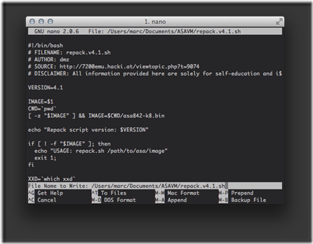
Create the repack.v4.1.sh script file with the nano text editor. Run the following command from Terminal:

$ nano $HOME/Documents/ASAVM/repack.v4.1.sh

Copy the code from GitHub and paste (command + v) the contents into the text editor window.

clip_image002

Save (control + o) the file, press the enter key to confirm, then exit (control + x) the nano text editor. 
4. Verify the contents of the ASAVM directory
We should have two files in the ASAVM directory. Run the following command from Terminal to verify:

$ ls -lh $HOME/Documents/ASAVM

total 49160

-rw-r--r-- 1 marc staff 24M Jan 8 18:50 asa842-k8.bin

-rw-r--r-- 1 marc staff 4.2K Jan 8 18:51 repack.v4.1.sh

5. Create the Fedora Linux virtual machine (VM)
Why do we need to create a Linux VM? The repack.v4.1.sh script needs to be run in Linux in order to complete the required operations for the creation of the bootable Cisco ASA ISO image file. 
Create the Fedora Linux VM with the following steps:

1. Open the VMware Fusion application.

2. Select File -> New... from the menu.

3. Select Install from disc or image.

4. Click the Continue button.

5. Click the Use another disc or disc image... button.

6. Navigate to and select the Fedora-Live-LXDE-i686-20-1.iso disc image.

7. Click the Open button.

8. Click the Continue button.

9. On the Choose Operating System screen, select Linux -> Fedora.

10. Click the Continue button.

11. Click the Finish button.

12. Click the Save button to save the virtual machine in the default Virtual Machines folder.

The Fedora Linux virtual machine will now automatically boot into the live disc environment which runs in the virtual machine's vRAM, rather than loading from the virtual hard disk drive. 
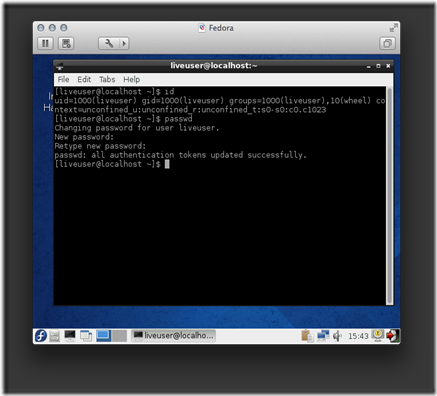
6. Set the password for the liveuser
We are currently logged in as the liveuser standard user account. The user account has no password by default, so we will set a password for it. This step is a prerequisite for upcoming tasks. Run the following command from LXTerminal:

[liveuser@localhost]$ passwd

Changing password for user liveuser.

New password: Pa$$worD1

Retype new password: Pa$$worD1

passwd: all authentication tokens updated successfully.

clip_image003

7. Start the SSH Server
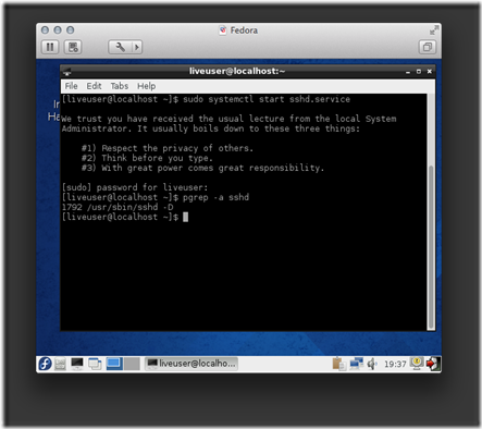
Our next task is to start the SSH Server daemon as we will need to enable remote access to the Linux VM. Run the following command fromLXTerminal:

[liveuser@localhost]$ sudo systemctl start sshd.service

...

[sudo] password for liveuser: Pa$$worD1

Verify the daemon process has started and is running. Run the following command from LXTerminal:

[liveuser@localhost]$ pgrep -a sshd

1792 /usr/sbin/sshd -D

clip_image004

8. Download and install software packages
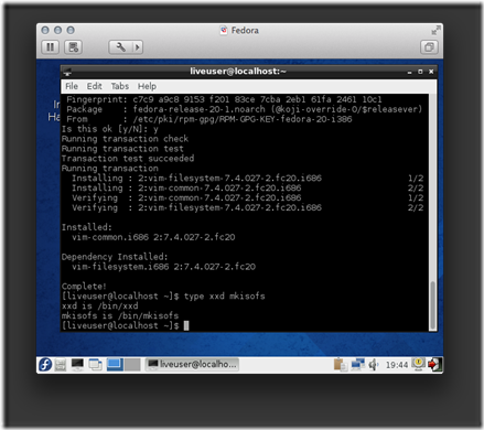
A couple of packages will need to be installed for the repack.v4.1.sh script to be able to create the bootable Cisco ASA ISO image file. Run the following command from LXTerminal:

[liveuser@localhost]$ sudo yum -y install vim-common mkisofs

...

Installed:

vim-common.i686 2:7.4.027-2.fc20

Dependency Installed:

vim-filesystem.i686 2:7.4.027-2.fc20

Complete!

Verify the packages have been successfully installed by running the following command from LXTerminal:

[liveuser@localhost]$ type xxd mkisofs

xxd is /bin/xxd

mkisofs is /bin/mkisofs

clip_image005

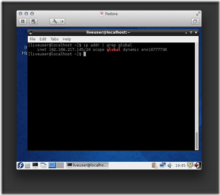
9. Get the IP configuration for the Fedora Linux VM
Your virtual machine will likely have a different dynamic IP address, so make sure to substitute the value in upcoming examples. Run the following command from LXTerminal:

[liveuser@localhost]$ ip addr | grep global

inet 192.168.217.145/24 scope global dynamic eno16777736

clip_image006

10. Transfer files from the Mac host to the Fedora Linux VM
Now that we have the IP address for the Linux VM guest, we can establish a scp connection and transfer the files from our Mac host to the remoteLinux VM guest. Run the following commands from Terminal:

$ cd $HOME/Documents/ASAVM

$ scp * liveuser@192.168.217.145:Documents

The authenticity of host '192.168.217.145 (192.168.217.145)' can't be established.

RSA key fingerprint is 62:38:a6:32:6b:d4:90:4a:7c:d8:10:b3:0c:85:d1:a5.

Are you sure you want to continue connecting (yes/no)? yes

Warning: Permanently added '192.168.217.145' (RSA) to the list of known hosts.

liveuser@192.168.217.145's password: Pa$$worD1

asa842-k8.bin 100% 24MB 24.0MB/s 00:01

repack.v4.1.sh 100% 4308 4.2KB/s 00:00

11. Create a SSH session to the Fedora Linux VM
Instead of continually entering commands in LXTerminal, within the virtual machine console, we will now simply establish a ssh session and enter the commands in our local Mac Terminal application. Run the following command from Terminal:

$ ssh liveuser@192.168.217.145

liveuser@192.168.217.145's password: Pa$$worD1

12. Run the repack.v4.1.sh script on the Fedora Linux VM (via SSH)
Run the following commands from Terminal:

[liveuser@localhost]$ cd $HOME/Documents

[liveuser@localhost]$ chmod +x repack.v4.1.sh

[liveuser@localhost]$ sudo ./repack.v4.1.sh ./asa842-k8.bin

[sudo] password for liveuser: Pa$$worD1

Repack script version: 4.1

Detected syslinux/cdrtools - ISO will be created

1359344+0 records in

1359344+0 records out

1359344 bytes (1.4 MB) copied, 2.4332 s, 559 kB/s

23697936+0 records in

23697936+0 records out

23697936 bytes (24 MB) copied, 97.922 s, 242 kB/s

/tmp/tmp.OFsCQZsGYc /home/liveuser/Documents

gzip: /home/liveuser/Documents/asa842-initrd-original.gz: decompression OK, trailing garbage ignored

114476 blocks

114476 blocks

114476 blocks

/home/liveuser/Documents

/tmp/tmp.KctycopD9w /home/liveuser/Documents

I: -input-charset not specified, using utf-8 (detected in locale settings)

Size of boot image is 4 sectors -> No emulation

21.05% done, estimate finish Wed Jan 8 22:46:41 2014

42.01% done, estimate finish Wed Jan 8 22:46:41 2014

63.01% done, estimate finish Wed Jan 8 22:46:41 2014

83.97% done, estimate finish Wed Jan 8 22:46:41 2014

Total translation table size: 2048

Total rockridge attributes bytes: 0

Total directory bytes: 2048

Path table size(bytes): 26

Max brk space used 0

23823 extents written (46 MB)

/home/liveuser/Documents

13. Verify the result
Four new files have been created in the directory. Run the following command from Terminal to confirm:

[liveuser@localhost]$ ll -h

-rw-r--r--. 1 root root 23M Jan 8 22:46 asa842-initrd.gz

-rw-r--r--. 1 root root 23M Jan 8 22:46 asa842-initrd-original.gz

-rw-r--r--. 1 liveuser liveuser 24M Jan 8 22:20 asa842-k8.bin

-rw-r--r--. 1 root root 1.3M Jan 8 22:44 asa842-vmlinuz

-rw-r--r--. 1 root root 47M Jan 8 22:46 asa.iso

-rwxr-xr-x. 1 liveuser liveuser 4.3K Jan 8 22:20 repack.v4.1.sh

We are finished with the interactive Linux portion, so close the ssh session to the the Fedora Linux VM. Run the following command fromTerminal:

[liveuser@localhost]$ exit

logout

Connection to 192.168.217.145 closed.

14. Transfer the asa.iso file from the Fedora Linux VM to the Mac
Run the following command from Terminal:

$ scp liveuser@192.168.217.145:Documents/asa.iso $HOME/Documents/ASAVM

liveuser@192.168.217.145's password: Pa$$worD1

asa.iso 100% 47MB 23.3MB/s 00:02

Verify the asa.iso file has been transferred to the local Mac file system. Run the following command from Terminal:

$ ls -lh $HOME/Documents/ASAVM

total 144456

-rw-r--r-- 1 marc staff 47M Jan 13 18:04 asa.iso

-rw-r--r-- 1 marc staff 24M Jan 13 17:48 asa842-k8.bin

-rw-r--r-- 1 marc staff 4.2K Jan 13 17:50 repack.v4.1.sh

The use of the Fedora Linux VM is complete. We can now shut down the Fedora Linux virtual machine in VMware Fusion.

15. Create the Cisco ASA virtual machine (VM)
We are ready to create the base Cisco ASA VM with the following steps:

1. Open the VMware Fusion application.

2. Select File -> New... from the menu.

3. Select Install from disc or image.

4. Click the Continue button.

5. Click the Use another disc or disc image... button.

6. Navigate to and select the asa.iso disc image.

7. Click the Open button.

8. Click the Continue button.

9. On the Choose Operating System screen, select Linux -> Other Linux 2.6x kernel.

10. Click the Continue button.

11. Click the Customize Settings button.

12. Name the virtual machine package as ASAVM.

13. Click the Save button to save the virtual machine in the default Virtual Machines folder.

16. Edit the virtual hardware for ASAVM
Make the following modifications in the Settings window: 

Component

Value

Processors

1 processor core

Memory

1024 MB

Network Adapter

Bridged Networking: Ethernet1

Network Adapter 2

Custom: Private to my Mac

Hard Disk (IDE)

0.50 GB

CD/DVD (IDE)

asa.iso

Sound Card

Remove Sound Card

USB & Bluetooth

Remove USB Controller

Printer

Remove Printer Port

# 16.1 Virtual Network Adapters
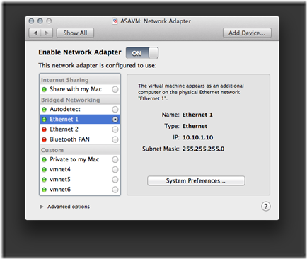
I've only tested Bridged Networking with a wired (i.e., no Wi-Fi) Ethernet connection. As newer Mac laptops don't have a physical Ethernet port, the StarTech USB31000S (Black) | USB31000SW (White) is a viable solution. For my labs that use a Cisco ASA as an Internet edge device, I define the first virtual network adapter as the logical outside interface that connects to the physical network.

clip_image007

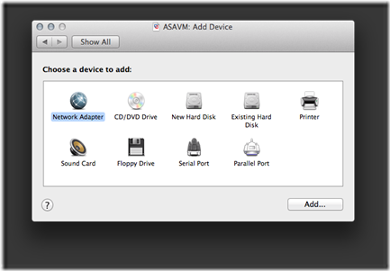
The virtual machine includes a single virtual network adapter by default. On the main Settings screen for the virtual machine, click the Add Device... button to add another Network Adapter device.

clip_image008

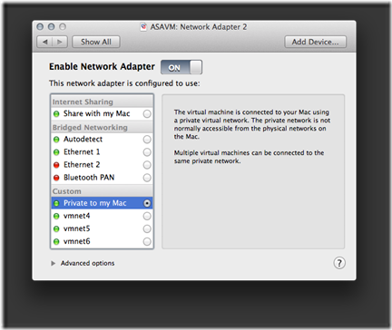
The second virtual network adapter will be set to Private to my Mac (VMnet1). For my labs that use a Cisco ASA as an edge device, I define the second virtual network adapter as the logical inside interface that connects to the virtual GNS3 network.

clip_image009

# 16.2 Virtual Hard Disk
Set the values for the following attributes of the virtual hard disk:

· Disk size: 0.50 GB

· Bus type: IDE

· Check Pre-allocate disk space

· Uncheck Split into multiple files

· Click the Apply button.

clip_image010

17. Edit the ASAVM configuration file
Close the VMware Fusion application before executing the steps in this section. 
Some settings can't be configured with the GUI, so we will need to directly edit the ASAVM .vmx (virtual machine configuration) file. My ASAVM virtual machine is located in the default VMware Fusion folder (directory), so I would edit the file with the following command from Terminal:

$ nano $HOME/Documents/Virtual\ Machines.localized/ASAVM.vmwarevm/ASAVM.vmx

# 17.1 Virtual Network Adapters
As you recall, we have two virtual network adapters configured for ASAVM. An issue is the model type is incorrect, so the Cisco ASA software won't recognize them upon boot. We can rectify this with the following steps:

· Locate the line with the ethernet0.present = "TRUE" statement.

· Insert a line directly below it with the ethernet0.virtualDev = "e1000e" statement.

...

ethernet0.present = "TRUE"

ethernet0.virtualDev = "e1000e"

ethernet0.connectionType = "custom"

ethernet0.wakeOnPcktRcv = "FALSE"

ethernet0.addressType = "generated"

ethernet0.linkStatePropagation.enable = "TRUE"

...

The previous steps will need to be repeated (substitute the vNIC index number) for every virtual network adapter attached to the virtual machine. So to complete my configuration, I would also insert the statement for my second virtual network adapter.

...

ethernet1.present = "TRUE"

ethernet1.virtualDev = "e1000e"

ethernet1.connectionType = "hostonly"

ethernet1.wakeOnPcktRcv = "FALSE"

ethernet1.addressType = "generated"

...

# 17.2 Virtual Serial Port
Just like with a physical Cisco ASA appliance, we can connect to our ASAVM with a console port connection. This is very similar to how we interface with our virtual routers in GNS3 (Dynamips). The following steps will create a virtual serial port that will allow us to emulate a console port connection via telnet.

· Locate the line with the serial0.present = "FALSE" statement.

· Change the value from FALSE to TRUE to enable it.

· Add some more statements to define the properties of the virtual component.

...

serial0.present = "TRUE"

serial0.yieldOnMsrRead = "TRUE"

serial0.fileType = "network"

serial0.fileName = "telnet://127.0.0.1:3456"

...

We are finished configuring the .vmx file, so lets save (control + o) the file, press the enter key to confirm, then exit (control + x) the nano text editor. 
18. Start ASAVM
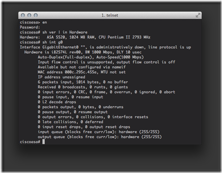
Reopen the VMware Fusion application and start the ASAVM virtual machine. Press the enter key at the boot: prompt, within the ASAVM virtual console, to load the ASA.

19. Virtual console port connection to ASAVM
Remember we need to emulate a console port connection via telnet, so enter the following command from Terminal:

$ telnet 127.0.0.1 3456

clip_image011

20. Lab integration
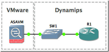
Your virtual machine should be up and running, but a network device serves little purpose unless it's actually connected to a network. Check out my Implement a Multivendor OSPF Lab with GNS3 and VMware Fusion post for a practical example.

Posted 14th January by Marc Weisel

Labels: Cisco GNS3 Linux Mac SSH VMware

Taken From: http://binarynature.blogspot.pt/2014/01/create-cisco-asa-vmware-fusion.html

More Info at: http://7200emu.hacki.at/viewtopic.php?t=9074
Saturday, February 22, 2014
Introduction to the Z File System (ZFS) - Linux

An Introduction to the Z File System (ZFS) for Linux

clip_image001

ZFS is commonly used by data hoarders, NAS lovers, and other geeks who prefer to put their trust in a redundant storage system of their own rather than the cloud.  It’s a great file system to use for managing multiple disks of data and rivals some of the greatest RAID setups.

Photo by Kenny Louie.

What is ZFS and Why Should I Use it?

The Z file system is a free and open source logical volume manager built by Sun Microsystems for use in their Solaris operating system.  Some of its most appealing features include:

Endless scalability

Well, it’s not technically endless, but it’s a 128-bit file system that’s capable of managing zettabytes (one billion terabytes) of data.  No matter how much hard drive space you have, ZFS will be suitable for managing it.

Maximum integrity

Everything you do inside of ZFS uses a checksum to ensure file integrity.  You can rest assured that your files and their redundant copies will not encounter silent data corruption.  Also, while ZFS is busy quietly checking your data for integrity, it will do automatic repairs anytime it can.

Drive pooling

The creators of ZFS want you to think of it as being similar to the way your computer uses RAM.  When you need more memory in your computer, you put in another stick and you’re done.  Similarly with ZFS, when you need more hard drive space, you put in another hard drive and you’re done.  No need to spend time partitioning, formatting, initializing, or doing anything else to your disks – when you need a bigger storage “pool,” just add disks.

RAID

ZFS is capable of many different RAID levels, all while delivering performance that’s comparable to that of hardware RAID controllers.  This allows you to save money, make setup easier, and have access to superior RAID levels that ZFS has improved upon.

Installing ZFS

Since we’re only covering the basics in this guide, we’re not going to install ZFS as a root file system.  This section assumes that you’re using ext4 or some other file system and would like to use ZFS for some secondary hard drives.  Here are the commands for installing ZFS on some of the most popular Linux distributions.

Solaris and FreeBSD should already come with ZFS installed and ready to use.

Ubuntu:

$ sudo add-apt-repository ppa:zfs-native/stable
$ sudo apt-get update
$ sudo apt-get install ubuntu-zfs

Debian:

$ su -
# wget http://archive.zfsonlinux.org/debian/pool/main/z/zfsonlinux/zfsonlinux_2%7Ewheezy_all.deb
# dpkg -i zfsonlinux_2~wheezy_all.deb
# apt-get update
# apt-get install debian-zfs

RHEL / CentOS:

$ sudo yum localinstall --nogpgcheck http://archive.zfsonlinux.org/epel/zfs-release-1-3.el6.noarch.rpm
$ sudo yum install zfs

If you have some other distribution, check out zfsonlinux.org and click on your distribution under the “Packages” list for instructions on how to install ZFS.

As we continue with this guide, we’re going to use Ubuntu because that seems to be the #1 choice for Linux geeks.  You should still be able to follow along no matter what, as the ZFS commands won’t change across different distributions.

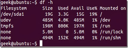
Installation takes quite a while, but once it’s finished, run $ sudo zfs list to make sure it’s installed correctly.  You should get an output like this:

clip_image002

We’re using a fresh installation of Ubuntu server right now, with only one hard drive.

clip_image003

Configuring ZFS

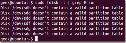
Now, let’s say we put six more hard drives into our computer.

$ sudo fdisk -l | grep Error will show us the six hard drives we just installed.  They’re currently unusable since they don’t contain any kind of partition table.

clip_image004

As we mentioned earlier, one of the nice things about ZFS is that we don’t need to bother with partitions (although you can if you want to).  Let’s start by taking three of our hard disks and putting them in a storage pool by running the following command:

$ sudo zpool create -f geek1 /dev/sdb /dev/sdc /dev/sdd

zpool create is the command used to create a new storage pool, -f overrides any errors that occur (such as if the disk(s) already have information on them), geek1 is the name of the storage pool, and /dev/sdb /dev/sdc /dev/sdd are the hard drives we put in the pool.

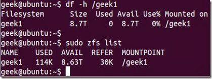
After you’ve created your pool, you should be able to see it with the df command or sudo zfs list:

clip_image005

As you can see, /geek1 has already been mounted and is ready to use.

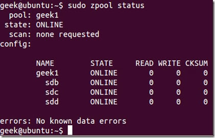
If you want to see which three disks you selected for your pool, you can run sudo zpool status:

clip_image006

What we’ve done so far is create a 9 TB dynamic stripe pool (effectively, RAID 0).  In case you’re not familiar with what that means, imagine we created a 3 KB file on /geek1.  1 KB would automatically go to sdb, 1 KB to sdc, and 1 KB to sdd.  Then when we go to read the 3 KB file, each hard drive would present 1 KB to us, combining the speed of the three drives.  This makes writing and reading data fast, but also means we have a single point of failure.  If just one hard drive fails, we will lose our 3 KB file.

Assuming that protecting your data is more important than accessing it quickly, let’s take a look at other popular setups.  First, we’ll delete the zpool we’ve created so we can use these disks in a more redundant setup:

$ sudo zpool destroy geek1

Bam, our zpool is gone.  This time, let’s use our three disks to create a RAID-Z pool.  RAID-Z is basically an improved version of RAID 5, because it avoids the “write hole” by using copy-on-write.  RAID-Z requires a minimum of three hard drives, and is sort of a compromise between RAID 0 and RAID 1.  In a RAID-Z pool, you’ll still get the speed of block-level striping but will also have distributed parity.  If a single disk in your pool dies, simply replace that disk and ZFS will automatically rebuild the data based on parity information from the other disks.  To lose all of the information in your storage pool, two disks would have to die.  To make things even more redundant, you can use RAID 6 (RAID-Z2 in the case of ZFS) and have double parity.

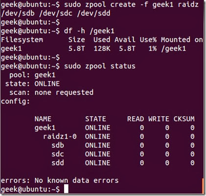
To accomplish this, we can use the same zpool create command as before but specify raidzafter the name of the pool:

$ sudo zpool create -f geek1 raidz /dev/sdb /dev/sdc /dev/sdd

clip_image007

As you can see, df -h shows that our 9 TB pool has now been reduced to 6 TB, since 3 TB is being used to hold parity information.  With the zpool status command, we see that our pool is mostly the same as before, but is using RAID-Z now.

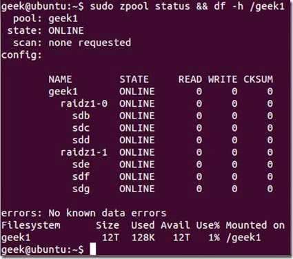
To show how easy it is to add more disks to our storage pool, let’s add the other three disks (another 9 TB) to our geek1 storage pool as another RAID-Z configuration:

$ sudo zpool add -f geek1 raidz /dev/sde /dev/sdf /dev/sdg

We end up with:

clip_image008

The Saga Continues…

We’ve barely scraped the surface of ZFS and its capabilities, but using what you’ve learned in this article you should now be able to create redundant storage pools of your data.  Check back with us for future articles about ZFS, see the man pages, and search around for the endless niche guides and Youtube videos covering ZFS functions.

Taken From: http://www.howtogeek.com/175159/an-introduction-to-the-z-file-system-zfs-for-linux/

Thursday, February 20, 2014

Huawei Switches Crash Course

Serial Connection
- Connect the Roll Over cable to the console port (RS232)
 
- Open Putty / Hiperterminal

- Configure the serial connection with following parameters:
    - Bits per Second: 9600
    - Parity: None
    - Stop Bits: 1
    - Flow Control: None

Clear Configuration (if the equipment is used)

- Connect the rollover cable to the console port

- Remove the power cable

- Reconnect the power cable
 
<Quidway>

Starting......

*******************************************
*                                         *
*   Quidway S3026G BOOTROM, Version 160   *
*                                         *
*******************************************

Copyright(C) 2000-2004 by HUAWEI TECHNOLOGIES CO.,LTD.
Creation Date   : Nov 03 2004, 18:41:59
CPU Type        : MIPS
CPU Clock Speed : 150MHz
Memory Size     : 64MB

Initialize LS66LTSU.......................OK!
SDRAM selftest............................OK!
FLASH selftest............................OK!
CPLD selftest.............................OK!
Switch chip selftest......................OK!
Switch SDRAM selftest.....................OK!
PHY selftest..............................OK!
Please check port leds..............finished!

The switch Mac is: 00E0-FC72-1912


Press Ctrl-B to enter Boot Menu...  0
Password:

             BOOT  MENU

1. Download application file to flash
2. Select application file to boot
3. Display all files in flash
4. Delete file from flash
5. Modify bootrom password
0. Reboot

Enter your choice(0-5): 4


No.    File Name                           
=================================================
1 *    S3026EFGTC-PWR-VRP310-r0036-32-a.bin
2      wnm2.2.2-0004.zip
3      snmpboots
4      vrpcfg.txt
Free space: 3938304 bytes
The current application file is S3026EFGTC-PWR-VRP310-r0036-32-a.bin

Please input the file number to delete: 4

Show the Running Config
display current-configuration

Show the Startup Config
display saved-configuration

Show the Startup Config
display current-configuration

Global Configuration Mode (Privileged Mode)
system-view

Undo Config. Commands
undo xxxxxx    ! equivalent to "no" in cisco

Change Hostname
sysname Huawei

Disable Spanning Tree (does not play well with cisco)
stp disable

Show a Vlan(s)
display vlan 1    ! show a vlan
display vlan       ! show vlans

Management Interface and Default Gateway
interface vlan-interface 1        ! managment vlan
ip address 1.1.1.1 255.0.0.0    ! management ip
undo shutdown                      ! activate the interface
ip route-static 0.0.0.0 0.0.0.0 129.102.0.2    ! default gateway

display ip routing-table          ! verify the default route

System View Password
password simple 20030422    ! plain text password
or
password cipher 20030422    ! encripted password

undo password                     ! remove password

Console Password
user-interface aux 0    
authentication-mode password
user privilege level 3

By default, ping, tracert, and telnet are
at visit level (0); display and debugging are
at monitoring level (1); all the configuration
commands are at configuration level (2);
and FTP, XMODEM, TFTP and commands for file
system operations are at management level (3).


set authentication password simple <password> ! plain text password
or
set authentication password cipher <password>  ! encrypted password

display user-interface    ! validate the password authentication

Telnet/SSH Password
user-interface vty 0 4
authentication-mode password
user privilege level 3

By default, ping, tracert, and telnet are
at visit level (0); display and debugging are
at monitoring level (1); all the configuration
commands are at configuration level (2);
and FTP, XMODEM, TFTP and commands for file
system operations are at management level (3).


set authentication password simple <password> ! plain text password
or
set authentication password cipher <password> ! encrypted password

display user-interface    ! validate the password authentication

Configure a Vlan on an Acess Port (unttaged)
interface Ethernet 0/1
  port access vlan

Configure a Vlan on an Range of Acess Ports (unttaged)
vlan 20                                             ! add vlan to the vlan DB
  port Ethernet 0/1 to Ethernet 0/23   ! range of access ports to add to the vlan

 
the switch automatically does the following:
<..>
interface Ethernet0/1
  port access vlan 10    ! configure a vlan on an access port
...
interface Ethernet0/23
  port access vlan 10    ! configure a vlan on an access port
<..>

Configure a Trunk Port (tagged)

interface Ethernet 0/24
  port link-type trunk                 ! define the port as trunk
  port trunk permit vlan all          ! permit all vlans
  description *** Uplink IF ***   ! port description

Save the Running Config

save

This will save the configuration in the flash memory.
The switch configurations will be written to flash.
Are you sure?[Y/N]
Now saving current configuration to flash memory.
Please wait for a while...
Save current configuration to flash memory successfully

LABNARIO - An AWSOME page with lots of tutorials about Huawei Networking is labnario, you should really check it out:

Cisco to Huawei Mapping 
Base:
http://lifeoflogs.blogspot.pt/2011/04/cisco-vs-huawei-essential-command.html

CISCO                                --> HUAWEI

ping                              --> ping
traceroute                     --> tracert
show                            --> display
show interfaces              --> display interface
Show ip route                 --> display routing-table
show ip interface            --> display ip interface
show version                  --> display version
show ip bgp                   --> display bgp routing-table
show clock                     --> display clock
show port                      --> display port-mapping
show flash                     --> dir flash: (on user view mode)
show logging                  --> display logbuffer
show snmp                    --> display snmp-agent statistics
show frame-relay pvc      --> display fr pvc-info
show users                    --> display users
show terminal length       --> screen-length disable
                                        undo screen-length disable
enable                          --> super
disable                          --> super 0 (number is privilege level from 0 to 3, where 3 is default and equivalent to “enable” on Cisco)
conf t                           --> system-view
exit                              --> quit
end                              --> return
show policy-map interface --> display qos policy interface
send -                           --> send (on user view mode)
show running-config         --> display current-configuration
show startup-config         --> display saved-configuration
write erase                     --> reset saved-configuration
write mem                      --> save
clear counters                --> reset (on user view mode)    
clear interface                --> reset counters interface
telnet                           --> telnet
enable secret                 --> Super pass cipher (system mode)
clock                            --> clock
no                                --> undo
debug / no debug            --> debugging / undo debugging
copy running-config         --> Save safely
terminal monitor              --> terminal monitor
terminal length                --> screen-length disable
                                         undo screen-length disable
terminal no monitor          --> undo terminal monitor
clear counters                -->    reset counters interface
clear interface                -->    reset counters interface
clear crypto                   -->    ipsec sa
                                            ike sa
clear access-list counters -->    reset acl counter all
reload                           -->    reboot
shutdown                      -->    shutdown
boot                             -->    boot bootrom
Aaa                              -->    hwtacacs scheme
tacacs-server                -->    hwtacacs scheme
snmp-server                  -->    tftp-server (in conf command)
router bgp                     -->    bgp
Router rip                      -->    rip
clear ip cef                    -->    reset ip fast-forwarding
clear ip route *              -->   reset ip routing-table statistics protocol all
Clear ip bgp                   -->    reset bgp all
Show tech                    -->    display diagnostic-information
Sh ip nat translation       -->    display nat session
Show Controller             -->    display controller
show dsl int atm 0         -->    display dsl status interface Atm 2/0
show atm pvc                -->    display atm pvc-info
debug pvc nego             -->    debug atm all
sho crypto isakmp sa      -->    display ike sa
sho crypto isakmp key     -->    display ike peer
sho crypto isakmp police  -->    display ike proposal

Sunday, February 16, 2014

Fix ‘File Path Too Long’ Error – Windows

How to Fix ‘File Path Too Long’ Error While Copying, Deleting or Opening Files, Without Using Third Party Applications

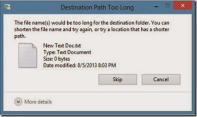
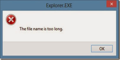
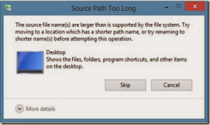
This is an error you might have experienced more at work than at home. You decided to copy a file or take a backup of it to another location or drive, you browse to the source location and starts copying. But you get this error, instead.

clip_image002 clip_image003

clip_image004

Why does it come?

There is a pre-defined character limit beyond which you cannot name a file or folder, and it varies from one OS to another. Mostly it varies between 256 and 260 characters. This is the character limit for a file name, which excludes the file path under which it is located, like “C:\Documents and Settings\Test User\Desktop\test file.txt”. But, when you copy a file from one location, it takes into account the entire file path. So, if the file is residing under a folder which is too deep or too long, that has a length beyond the set-limit, you will get errors like the ones shown above.

How do I know that the file path length is causing the issue?

  • One way you will know is definitely from the error messages similar to the ones above which clearly mentions the problem.
  • Some other times, it won’t. You will simply get a message saying ‘Cannot Copy’ in the title.
  • Or, some other times, the files won’t open properly. They would open and close instantly without giving any errors.
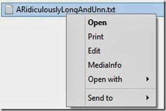
  • Also when you right-click such files, the number of options available in the right-click menu would also be limited compared to other files.

clip_image005

All these are caused by those incredibly long file paths.

So, how can I copy the files or fix this issue?

There are a couple of ways you can fix this easily without the use of any 3rd party applications.

  1. Check the folder path, and shorten some of the folder names in between thereby reducing the file path length. You don’t necessarily need to put the folder name as ‘Mission Impossible Three’ when you can still recognize it as ‘MI 3.’
  2. The main thing many people miss when they save a file or folder their Desktop is that the actual path to that folder in desktop is either ‘C:\Documents and Settings\%username%\Desktop’ or ‘C:\Users\%username%\Desktop’ depending on your OS. So as you can see, its already longer than you thought it is. Go to Start — Run and type ‘cmd‘ and press OK, or click start/press windows key and type ‘Command Prompt‘. Once in the command prompt window, type the following command :

subst V: “C:\TheRidiculouslyLongFolderName

WhichYouDontNeedAtAll” ,

where

subst = substitute command

V = a drive letter of my choice, you can select your own.

C:\TheRidiculouslyLongFolderNameWhichYouDontNeedAtAll = the file path you want to shorten. Change it according to your situation.

clip_image006

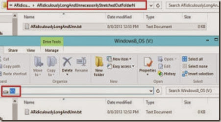
So, basically this command would convert the entire folder path you provide in the command, into a single temporary drive letter, like V in this case, which gets created in My Computer. Now all you need to do is, go to the My Computer, and open the V drive, and copy the data from there.

clip_image007

Note : To remove the new drive from My Computer, go to Command Prompt again and type subst V: /d

There you have it, try this the next time you get the error, and see how it goes. If you are still confused, let me know in the comments section below.

Taken From: http://vimalsuresh.com/2013/08/08/how-to-fix-file-path-too-long-error-while-copying-deleting-or-opening-files-without-using-third-party-applications/

More Details on “subst”, can be found at:

Tuesday, February 11, 2014

Beginner’s Guide to IPTables (Linux Firewall)

The Beginner’s Guide to iptables, the Linux Firewall

clip_image002

Iptables is an extremely flexible firewall utility built for Linux operating systems. Whether you’re a novice Linux geek or a system administrator, there’s probably some way that iptables can be a great use to you. Read on as we show you how to configure the most versatile Linux firewall.

About iptables

iptables is a command-line firewall utility that uses policy chains to allow or block traffic. When a connection tries to establish itself on your system, iptables looks for a rule in its list to match it to. If it doesn’t find one, it resorts to the default action.

iptables almost always comes pre-installed on any Linux distribution. To update/install it, just retrieve the iptables package:

sudo apt-get install iptables

There are GUI alternatives to iptables like Firestarter, but iptables isn’t really that hard once you have a few commands down. You want to be extremely careful when configuring iptables rules, particularly if you’re SSH’d into a server, because one wrong command can permanently lock you out until it’s manually fixed at the physical machine.

Types of Chains

iptables uses three different chains: input, forward, and output.

Input – This chain is used to control the behavior for incoming connections. For example, if a user attempts to SSH into your PC/server, iptables will attempt to match the IP address and port to a rule in the input chain.

Forward – This chain is used for incoming connections that aren’t actually being delivered locally. Think of a router – data is always being sent to it but rarely actually destined for the router itself; the data is just forwarded to its target. Unless you’re doing some kind of routing, NATing, or something else on your system that requires forwarding, you won’t even use this chain.

There’s one sure-fire way to check whether or not your system uses/needs the forward chain.

iptables -L -v

clip_image003

The screenshot above is of a server that’s been running for a few weeks and has no restrictions on incoming or outgoing connections. As you can see, the input chain has processed 11GB of packets and the output chain has processed 17GB. The forward chain, on the other hand, has not needed to process a single packet. This is because the server isn’t doing any kind of forwarding or being used as a pass-through device.

Output – This chain is used for outgoing connections. For example, if you try to ping howtogeek.com, iptables will check its output chain to see what the rules are regarding ping and howtogeek.com before making a decision to allow or deny the connection attempt.

The caveat

Even though pinging an external host seems like something that would only need to traverse the output chain, keep in mind that to return the data, the input chain will be used as well. When using iptables to lock down your system, remember that a lot of protocols will require two-way communication, so both the input and output chains will need to be configured properly. SSH is a common protocol that people forget to allow on both chains.

Policy Chain Default Behavior

Before going in and configuring specific rules, you’ll want to decide what you want the default behavior of the three chains to be. In other words, what do you want iptables to do if the connection doesn’t match any existing rules?

To see what your policy chains are currently configured to do with unmatched traffic, run theiptables -L command.

clip_image004

As you can see, we also used the grep command to give us cleaner output. In that screenshot, our chains are currently figured to accept traffic.

More times than not, you’ll want your system to accept connections by default. Unless you’ve changed the policy chain rules previously, this setting should already be configured. Either way, here’s the command to accept connections by default:

iptables --policy INPUT ACCEPT
iptables --policy OUTPUT ACCEPT
iptables --policy FORWARD ACCEPT

By defaulting to the accept rule, you can then use iptables to deny specific IP addresses or port numbers, while continuing to accept all other connections. We’ll get to those commands in a minute.

If you would rather deny all connections and manually specify which ones you want to allow to connect, you should change the default policy of your chains to drop. Doing this would probably only be useful for servers that contain sensitive information and only ever have the same IP addresses connect to them.

iptables --policy INPUT DROP
iptables --policy OUTPUT DROP
iptables --policy FORWARD DROP

Connection-specific Responses

With your default chain policies configured, you can start adding rules to iptables so it knows what to do when it encounters a connection from or to a particular IP address or port. In this guide, we’re going to go over the three most basic and commonly used “responses”.

Accept – Allow the connection.

Drop – Drop the connection, act like it never happened. This is best if you don’t want the source to realize your system exists.

Reject – Don’t allow the connection, but send back an error. This is best if you don’t want a particular source to connect to your system, but you want them to know that your firewall blocked them.

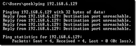
The best way to show the difference between these three rules is to show what it looks like when a PC tries to ping a Linux machine with iptables configured for each one of these settings.

Allowing the connection:

clip_image005

Dropping the connection:

clip_image006

Rejecting the connection:

clip_image007

Allowing or Blocking Specific Connections

With your policy chains configured, you can now configure iptables to allow or block specific addresses, address ranges, and ports. In these examples, we’ll set the connections to DROP, but you can switch them to ACCEPT or REJECT, depending on your needs and how you configured your policy chains.

Note: In these examples, we’re going to use iptables -A to append rules to the existing chain. iptables starts at the top of its list and goes through each rule until it finds one that it matches. If you need to insert a rule above another, you can use iptables -I [chain] [number] to specify the number it should be in the list.

Connections from a single IP address

This example shows how to block all connections from the IP address 10.10.10.10.

iptables -A INPUT -s 10.10.10.10 -j DROP

Connections from a range of IP addresses

This example shows how to block all of the IP addresses in the 10.10.10.0/24 network range. You can use a netmask or standard slash notation to specify the range of IP addresses.

iptables -A INPUT -s 10.10.10.0/24 -j DROP

or

iptables -A INPUT -s 10.10.10.0/255.255.255.0 -j DROP

Connections to a specific port

This example shows how to block SSH connections from 10.10.10.10.

iptables -A INPUT -p tcp --dport ssh -s 10.10.10.10 -j DROP

You can replace “ssh” with any protocol or port number. The -p tcp part of the code tells iptables what kind of connection the protocol uses.  If you were blocking a protocol that uses UDP rather than TCP, then -p udp would be necessary instead.

This example shows how to block SSH connections from any IP address.

iptables -A INPUT -p tcp --dport ssh -j DROP

Connection States

As we mentioned earlier, a lot of protocols are going to require two-way communication. For example, if you want to allow SSH connections to your system, the input and output chains are going to need a rule added to them. But, what if you only want SSH coming into your system to be allowed? Won’t adding a rule to the output chain also allow outgoing SSH attempts?

That’s where connection states come in, which give you the capability you’d need to allow two way communication but only allow one way connections to be established. Take a look at this example, where SSH connections FROM 10.10.10.10 are permitted, but SSH connections TO 10.10.10.10 are not. However, the system is permitted to send back information over SSH as long as the session has already been established, which makes SSH communication possible between these two hosts.

iptables -A INPUT -p tcp --dport ssh -s 10.10.10.10 -m state --state NEW,ESTABLISHED -j ACCEPT

iptables -A OUTPUT -p tcp --sport 22 -d 10.10.10.10 -m state --state ESTABLISHED -j ACCEPT

Saving Changes

The changes that you make to your iptables rules will be scrapped the next time that the iptables service gets restarted unless you execute a command to save the changes.  This command can differ depending on your distribution:

Ubuntu:

sudo /sbin/iptables-save

Red Hat / CentOS:

/sbin/service iptables save

Or

/etc/init.d/iptables save

Other Commands

List the currently configured iptables rules:

iptables -L

Adding the -v option will give you packet and byte information, and adding -n will list everything numerically. In other words – hostnames, protocols, and networks are listed as numbers.

To clear all the currently configured rules, you can issue the flush command.

iptables -F

Taken From: http://www.howtogeek.com/177621/the-beginners-guide-to-iptables-the-linux-firewall/

Friday, February 7, 2014

Sainsmart 2-Channel 5V Relay - Arduino / Raspberry Pi

Introduction

clip_image002

The Arduino Relay module allows a wide range of microcontroller such as Arduino, Raspberry Pi, AVR ,PIC, ARM with digital outputs to control larger loads and devices like AC or DC Motors, electromagnets, solenoids, and incandescent light bulbs. This module is designed to be integrated with 2 relays that it is capable of control 2 relays.The relay shield use one QIANJI JQC-3F high-quality relay with rated load 7A/240VAC,10A/125VAC,10A/28VDC.The relay output state is individually indicated by a light-emitting diode.

Features

  • Model: SRD-05VDC-SL-C
  • Number of Relays: 2
  • Control signal: TTL level
  • Rated load: 7A/240VAC 10A/125VAC 10A/28VDC
  • Contact action time: 10ms/5ms

Pin definition

clip_image004

  • COM - Common pin: This is source pin, that starts connected to NC, and connects to NO when you apply 0v / GND (active low)
  • NC (Normally Closed): in which case NC is connected with COM when INT1 is set low and disconnected when INT1 is high;
  • NO (Normally Open): in which case NO is disconnected with COM1 when INT1 is set low and connected when INT1 is high.
  • INT 1- Relay 1 control port: changes from the COM–>NO to the COM–>NC when you apply 0v / GND (active low)
  • INT 2- Relay 2 control port: changes from the COM à NO to the COM à NC when you apply 0v / GND (active low)

Video Explaination

Usage with Arduino

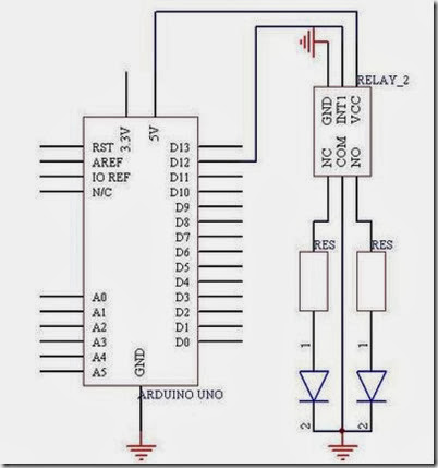
clip_image005

Example Code

int Relay = 12;

void setup()
{
    pinMode(Relay, OUTPUT); //Set Pin12 as output
}

void loop()
{
    digitalWrite(Relay, HIGH); //Turn off relay
    delay(2000);
    digitalWrite(Relay, LOW); //Turn on relay
    delay(2000);
}

Videos

How to buy


Based On:

Tuesday, February 4, 2014

Share a VM on VMWare Workstation (aka Server Mode)

The virtual machine sharing service is not available in VMWare Workstation 8

Posted on April 16, 2012 by Ben

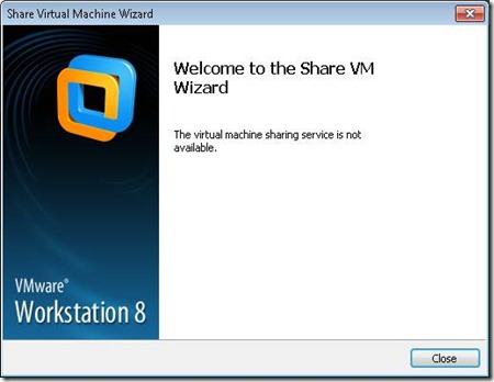
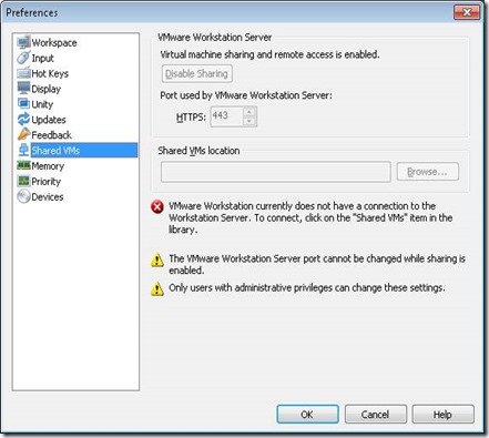
I wanted to share a VM, but this error message appeared when doing so:

clip_image002

The virtual machine sharing service is not available.

Solution

Changing the TCP Port that VMWare Workstation uses for the Shared VMs feature did the trick!

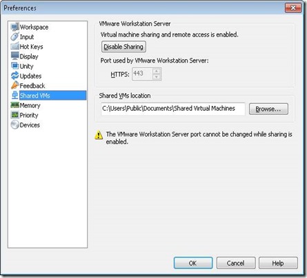
First startup VMWare Workstartion as an admin, otherwise you don’t have sufficient permissions;

clip_image004

Started as administrator:

clip_image006

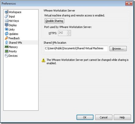
Stop the service first, by hitting the “Disable Sharing” button. Then change the port number, and start the the sharing service again. I changed it to 242;

clip_image008

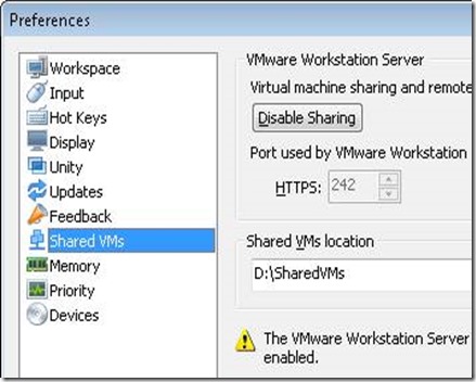
Before sharing a VM, I changed the location where all shared VMs are located. Because I wanted VMs on a second SSD.

clip_image010

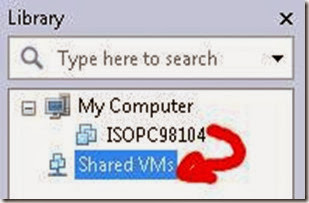
Share a VM by moving  a machine into the Shared VMs container in the Library;

clip_image012

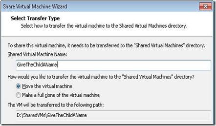
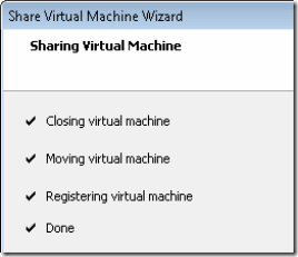
The Share VM Wizard starts. Transfer the VM to the “Shared Virtual Machines” directory (the one I changed a minute ago);

clip_image014

clip_image015

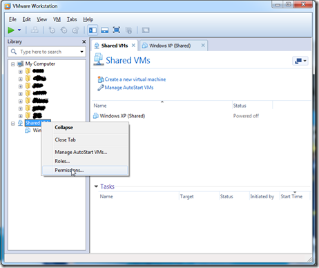
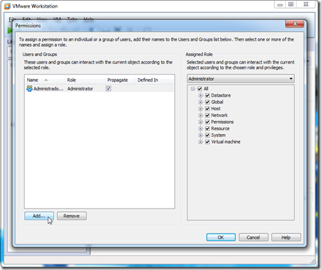
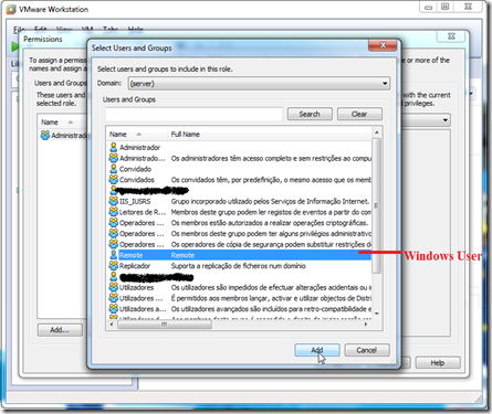
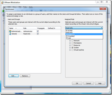
Adding a user for remote access (this is a windows user, but it can´t be you current user)

ScreenShot019

ScreenShot020

ScreenShot021

ScreenShot022

On your local firewall you must allow the following TCP Ports:

  • HTTPs: TCP port 242 (in this case)
  • MKS: TCP port 902 (without this it doesn´t display the remote VM desktop)

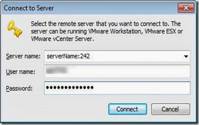
Now connect to the machine where the VM is stored using VMware Workstation 8 on another machine. But specify the port name we just changed!

clip_image017clip_image019

Maybe you have to add permissions on the remote VM server, but the above should solve the “The virtual machine sharing service is not available” issue.

ONE THOUGHT ON “THE VIRTUAL MACHINE SHARING SERVICE IS NOT AVAILABLE IN VMWARE WORKSTATION 8”

Based On: http://esense.be/33/2012/04/16/the-virtual-machine-sharing-service-is-not-available-in-vmware-workstation-8/