Saturday, December 15, 2012

Android Emulator on Linux (Ubuntu)

When Google announced and released Android, back in October 2008, everyone knew that it would become the best operating system for mobile devices. Not only is Android open source, but it also comes with a Software Development Kit, which offers the necessary APIs and utilities for developers to easily build powerful applications for Android-powered mobile devices. The following tutorial was created especially for those of you who want to test the Android platform and install various applications, on the popular Ubuntu operating system. OK, so let's get started... shall we?


Grab the Android SDK from Softpedia and save the file on your home folder.

Editor's note: The tutorial was rewritten for the new Android 2.0 or later, which provides a graphical user interface to setup a virtual device and the SD card. This makes everything a lot easier. No more command-line madness!
Step 1- Installing the requirements
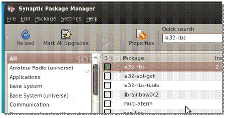
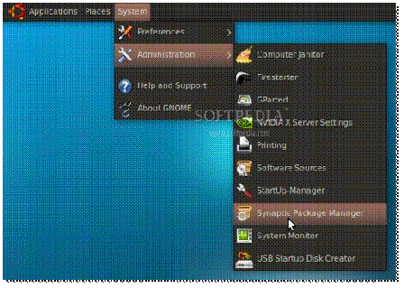
Until the download is over, make sure that you have Java installed and the 32-bit libraries (for the x86_64 users ONLY). If you don't have Java (or the 32-bit libraries), go to System -> Administration -> Synaptic Package Manager...

clip_image002

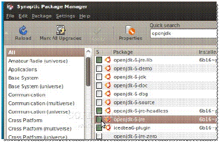
...search for openjdk and double-click on the openjdk-6-jre entry...

clip_image004

...then, search for ia32-libs (ONLY if you are on a x86_64 machine), and double-click on the ia32-libs entry...

clip_image006

Now, click the "Apply" button to install the packages. Wait for the packages to be installed and close Synaptic when the process is finished.
Step 2 - Android Setup
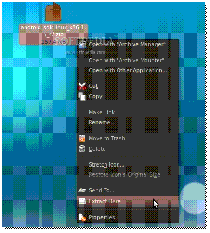
When the Android SDK download is over, right-click on the file and choose the "Extract Here..." option...

clip_image008

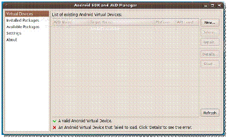
Enter the extracted folder, then enter the tools folder and double click the android file. Click on the "Run" button when you will be asked what you want to do, and the Android SDK and AVD Manager interface will appear...

clip_image010

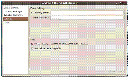
Go to the "Settings" section and make sure you check the "Force https://..." box. Click the "Save & Apply" button....

clip_image012

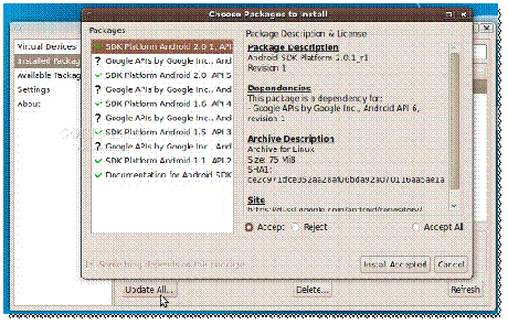
Now go to the "Installed Packages" section and click the "Update All" button. A window will appear with all the available updates. Click the "Install Accepted" button...

clip_image014

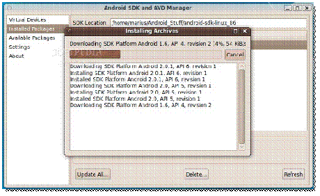
...and wait for the packages to be downloaded and installed. It will take a while if you have a slow bandwidth, so go see a movie or something until it finishes...

clip_image016

Close the update window when it's done and you will see all the installed SDKs in the "Installed Packages" section.
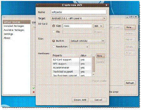
And now, let's create the virtual device. Go to the "Virtual Device" section and click the "New" button. In the new window do the following:
- put a name to the device;
- select a target (Android system);
- put the size for the SD Card;
- add the hardware you want have in the emulator.
It should look something like this...

clip_image018

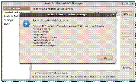
Click the "Create AVD" button when you're done setting up the virtual device and wait for it to finish. It takes about 1 minute, and you'll be notified by a pop-up...

clip_image020

Note: In the above setup, we've created a virtual device for Android 2.0.1 with a 2 GB SD card and the following hardware components: SD Card, GPS, Accelerometer, Track-ball and touch-screen.
Now click the "Start" button, and the "Launch" button from the next dialog, and the emulator will start...

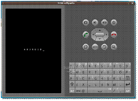
clip_image022

clip_image024

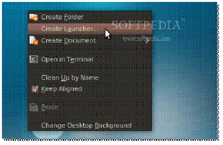
To make things a lot simpler let's create a desktop shortcut, so you won't have to open the terminal every time and type some command, in order to start the Android emulator. Therefore, right-click on your desktop and choose the "Create Launcher..." option...

clip_image026

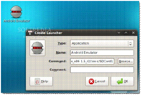
In the Create Launcher window, type "Android Emulator" (without quotes) in the Name field, and paste the below line in the Command field. Optionally, you can also put a nice icon if you click the icon button on the left...
/home/YOURUSERNAME/android-sdk-linux_86/tools/emulator @softpedia

clip_image028

Note: Please replace YOURUSERNAME and the name of the Android Virtual Device (softpedia in our case) with your USERNAME and the name you gave to the virtual device. DO NOT REMOVE the @ sign.
Step 3 - Run applications in Android
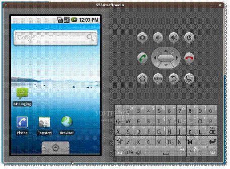
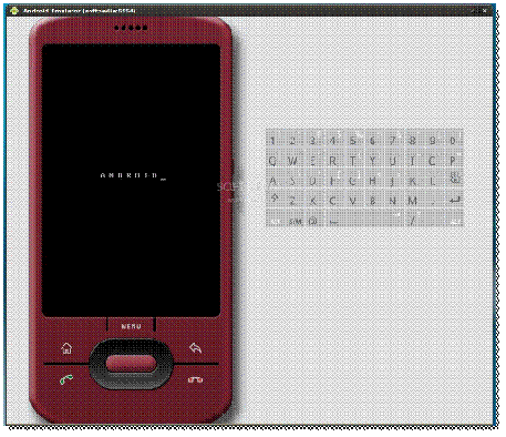
All you have to do now is double-click that desktop shortcut you've just created. The Android emulator will start. Wait for the operating system to load...

clip_image030

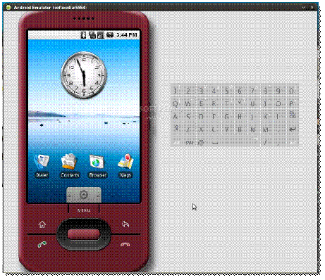
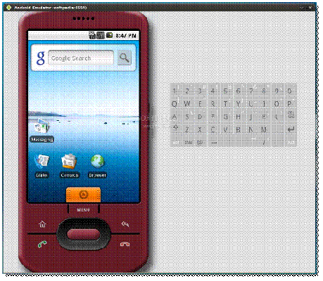
When the Android operating system has loaded, you can install and test applications. If you are used with the Android platform, you already know how to do that, but if this is your first time... follow the next instructions.

clip_image032

Android 1.1

clip_image034

Android 1.5

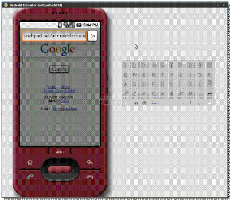
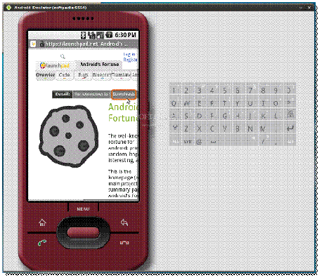
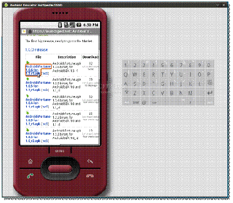
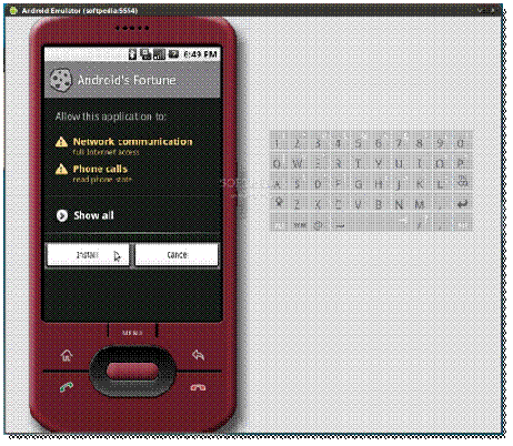
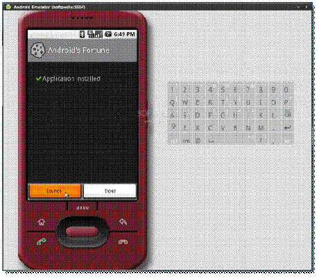
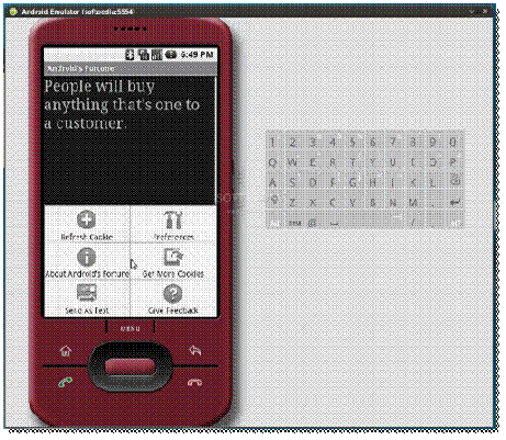
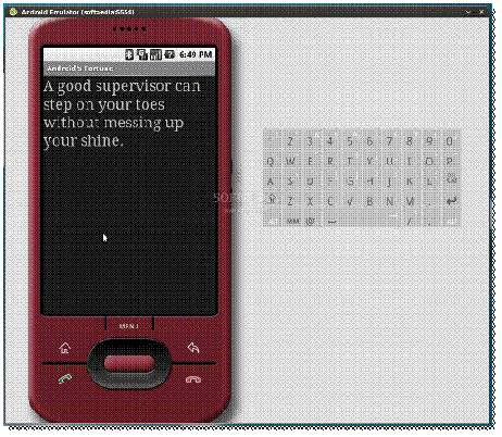
Click the Browser icon, wait for the browser to load and click Menu -> Go to URL. Enter the address from where you can download an Android application with the apk extension. For example, we've easily installed Android's Fortune from Launchpad...

clip_image036

clip_image038

clip_image040

clip_image042

clip_image044

clip_image046

clip_image048

...all you have to do is follow the on-screen instructions!
Have fun, and do not hesitate to comment if you want to know more about Android, or if you're stuck somewhere in the tutorial.

Taken From: http://news.softpedia.com/news/How-to-Run-Android-Applications-on-Ubuntu-115152.shtml
Monday, November 26, 2012

USB Drives on Nexus 7 and Other Android Devices

How To Use USB Drives With the Nexus 7 and Other Android Devices

clip_image001

The Nexus 7 may not have a lot of storage space – especially the original 8 GB model – but you can connect a USB drive to it if you want to watch videos or access other files.

Unfortunately, Android doesn’t automatically mount USB drives by default. You’ll need to root your device to enable support for USB drives.

What You’ll Need

You’ll need four things to do this:

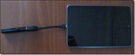
· A USB OTG adapter cable: One end of this cable plugs into the micro USB connector on your Nexus 7 (or other device) and one end allows you to connect standard USB 2.0 devices, such as USB drives. These cables can be had for less than $1 online. USB OTG stands for USB On-The-Go.

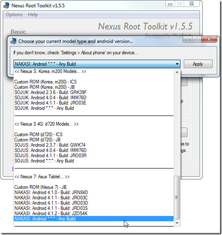
· A rooted Nexus 7 (or other Android tablet or smartphone): We’ve covered using the Nexus Root Toolkit to easily root Nexus devices. If you’ve previously rooted your device and since updated the operating system, it’s just a matter of opening the Nexus Root Toolkit and clicking the Root button again. (The Nexus Root Toolkit currently does not included support for Android 4.2. If you’re using Android 4.2 on your Nexus, select “Any Build” under the device.)

clip_image002

· The StickMount app: StickMount is available for free from Google Play. Note that StickMount only works if your device is rooted.

· ES File Explorer or another file manager app: We’ll be using ES FIle Explorer here, but you can also use another file manager if you prefer it.

Accessing a USB Drive

With your device rooted, plug one end of the USB OTG cable into it and connect the USB drive to the other end of the cable.

clip_image001[1]

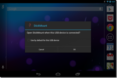
You’ll see a StickMount prompt when the drive is connected. Tap OK and StickMount will make the files on the USB device accessible.

clip_image003

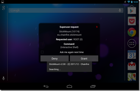
You’ll need to grant root access to StickMount. The process will fail here if you aren’t rooted.

clip_image004

If you agree to both dialogs and select the Use by default option in the first dialog, you won’t see any dialogs when you next connect your USB drive – this will all happen automatically.

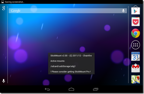
You’ll see a notification indicating that StickMount successfully mounted the device under /sdcard/usbStorage.

clip_image005

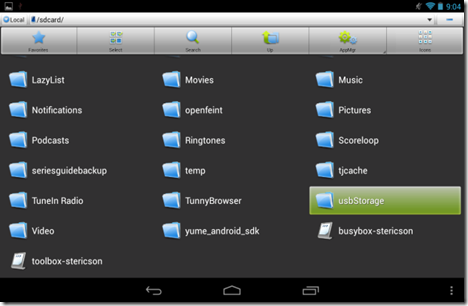
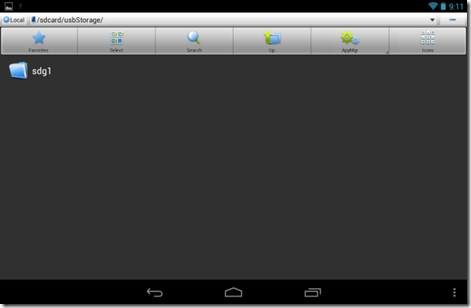
Open the ES File Explorer app on your device and tap the usbStorge folder.

clip_image006

You’ll see at least one folder inside the usbStorage folder. These folders represent the different partitions on your connected devices.

clip_image007

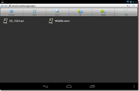
Tap the folder and you’ll see the files inside it. Tap or long-press the files to open them or manipulate them normally.

clip_image008

For example, this is particularly useful for watching video files, which can take up a lot of space on your tablet.

clip_image009

When you’re done, you can tap the StickMount option in your notification tray to unmount (eject) the drive and then disconnect it. This notification also informs you when StickMount has successfully mounted a drive.

clip_image010


While the cable is a tad bit bulky, it’s still convenient for watching videos on an airplane or while sitting around your house. You can also use it to move files around for any other purpose, just as you’d use a USB drive on a computer

Taken From: http://www.howtogeek.com/129800/how-to-use-usb-drives-with-the-nexus-7-and-other-android-devices/

Sunday, October 28, 2012

Shrink Your Arduino Projects (ATtiny)

Ever since I started making projects with the Arduino, I’ve had a desire to shrink them down to a single, small circuit board. One of my first projects, a customizable SLR intervalometer, was packed in a phonebook-sized cardboard box and used the Arduino Deumilanove connected to a breadboard with jumper wires. I brought the box out to Central Park at 5am to make a timelapse of the sunrise, but when I got to the park, I spent 20 minutes fixing the connections between the Arduino, the breadboard, and the components. Since then, I’ve explored a few different ways of shrinking projects down and making them more robust. For the intervalometer, I designed a circuit board that had female header pins to seat an Arduino Nano. It was a huge improvement on the design, but I knew I could do a lot better.

I tried to teach myself AVR programming, but ran into a lot of snags along the way. By the time I got an LED to blink, I had invested hours in the project (a stark contrast to my first Arduino experience) and was feeling quite discouraged. I also tried using PICAXE chips. While it was much easier to get started with these chips than with AVR programming, I felt like I was abandoning all my years of C programming to learn a form of BASIC that’s an entirely different animal from when I used it as a kid.

Blinking an LED with an ATTiny Chip
When I came across the Programming an ATtiny w/ Arduino Tutorial below, I was elated. They walk you through the process of using the Arduino IDE and programming language to program 8 pin ATtiny45 or ATtiny85 chips. Not only that, but they also walk you through using an Arduino board to act as the programmer, or ISP. I had everything I needed, except for the chips, so I eagerly awaited my rush shipment of ATtinies.

I followed the tutorial and found that it was actually rather easy to program these little chips using the Arduino code and IDE. I tried out the basic digital and analog I/O functions and they all worked as expected. I did a little experimentation with a few other functions with some success, so your milage may vary. To test it all out, I even made a cute little blinky toy within about an hour. I’m now thinking about revisiting my intervalometer project and shrinking it down from a cardboard box to a mini Altoids tin!

Watch the video here

Programming an ATtiny w/ Arduino Tutorial

This tutorial shows you how to program an ATtiny45 or ATtiny85 microcontroller using the Arduino software and hardware. The ATtiny45 and ATtiny85 are small (8-leg), cheap ($2-3) microcontrollers that are convenient for running simple programs.

This tutorial is obsolete! See the updated version of this tutorial (with support for Arduino 1.0).

They are almost identical, except that the ATtiny85 has twice the memory of the ATtiny45 and can therefore hold more complex programs. We like to use both of them with paper circuits and other craft electronics. To program them, we’ll use a port of the Arduino core libraries created by Alessandro Saporetti and slightly modified by HLT.

Materials and Tools

For this tutorial, you’ll need:

  • Arduino Uno or Duemilanove (w/ an ATmega328, not an older board with an ATmega168)
  • ATtiny45 or ATtiny85 (8-pin DIP package)
  • a 10 uF capacitor (e.g. from Sparkfun or from Digi-Key)
  • a breadboard
  • jumper wires
  • For more information, see our list of materials and parts and our list of prototyping supplies.

    Software

    You’ll need the Arduino software (version 0022) and a plugin to add support for the ATtiny45/85. Installation instructions for the Arduino software are available for Windows and for Mac OS X.

    Download: Arduino software, attiny45_85.zip

    The ATtiny45 / ATtiny85 Microcontroller

    Here’s the pinout of the ATtiny45 and ATtiny85:

    clip_image002

    Installing ATtiny45 / ATtiny85 support in Arduino

    · Download: attiny45_85.zip

    · Locate your Arduino sketchbook folder (you can find its location in the preferences dialog in the Arduino software)

    · Create a new sub-folder called “hardware” in the sketchbook folder.

    · Copy the attiny45_85 folder from the attiny45_85.zip to the hardware folder.

    · Restart the Arduino development environment.

    Turning the Arduino board into a programmer

    We’re going to use the Arduino board to program the ATtiny45 or ATtiny85. First,
    we’ll need to turn the Arduino board into an “in-system programmer” (ISP). To this:

  • Run the Arduino development environment.
  • Open the ArduinoISP sketch from the examples menu.
  • Select the board and serial port that correspond to your Arduino board.
  • Upload the ArduinoISP sketch.
  • Connecting the Arduino board and the ATtiny

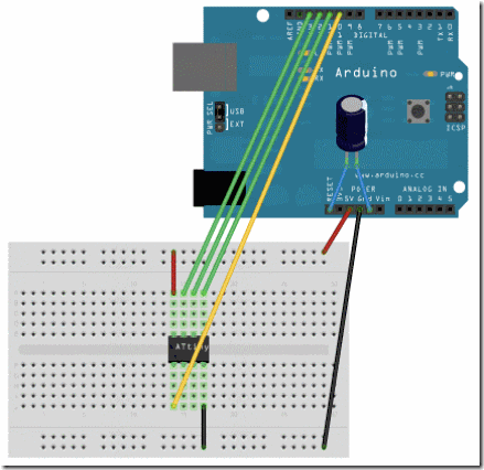
    We’ll connect the Arduino board to the ATtiny as shown in the following diagram. Use the dot in the corner of the ATtiny to orient it properly. We’ll also connect a 10 uF capacitor between reset and ground on the Arduino board as shown in the diagram (the stripe on the capacitor that’s marked with a negative sign (-) should go to ground). The capacitor prevents the Arduino board from resetting (which starts the bootloader), thus ensuring that the Arduino IDE talks to the ArduinoISP (not the bootloader) during the upload of sketches. (The capacitor is needed if you’re using an Arduino Uno, and might also be necessary for an Arduino Duemilanove.)

    clip_image004

    Pin connections:

  • ATtiny Pin 2 to Arduino Pin 13 (or SCK of another programmer)
  • ATtiny Pin 1 to Arduino Pin 12 (or MISO of another programmer)
  • ATtiny Pin 0 to Arduino Pin 11 (or MOSI of another programmer)
  • ATtiny Reset Pin to Arduino Pin 10 (or RESET of another programmer)
  • Programming the ATtiny45 or ATtiny85

    Next, we can use the Arduino as an ISP to upload a program to the ATtiny45/85:

  • Open the Blink sketch from the examples menu.
  • Change the pin numbers from 13 to 0.
  • Select “ATtiny45 (w/ Arduino as ISP)” or “ATtiny85 (w/ Arduino as ISP)” from the Tools > Board menu (leave the serial port set to that of your Arduino board).
  • Upload the sketch.
  • You’ll probably get the following message, but don’t worry, the upload should have worked anyway:
  • avrdude: please define PAGEL and BS2 signals in the configuration file for part ATtiny85


    avrdude: please define PAGEL and BS2 signals in the configuration file for part ATtiny85


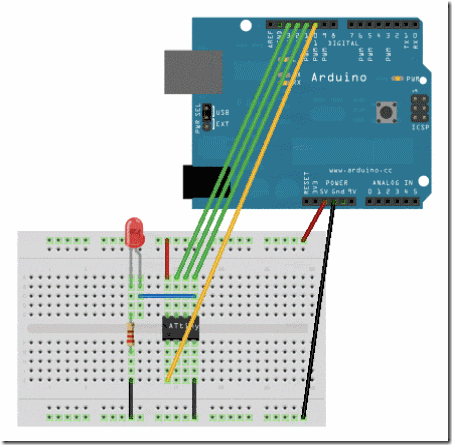
    Now, connect an LED and see if it blinks.

    clip_image006


    Reference


    The following Arduino commands should be supported:


    Taken From:


    http://blog.makezine.com/2011/10/10/how-to-shrinkify-your-arduino-projects/


    http://hlt.media.mit.edu/?p=1229

    Sunday, October 21, 2012

    Cisco Vlan Tunneling (Double Tagging / QinQ)

    IEEE 802.1Q Tunneling

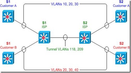
    IEEE 802.1Q tunneling can be used to achieve simple layer two VPN connectivity between sites by encapsulating one 802.1Q trunk inside another. The topology below illustrates a common scenario where 802.1Q (or "QinQ") tunneling can be very useful.

    clip_image002

    A service provider has infrastructure connecting two sites at layer two, and desires to provide its customers transparent layer two connectivity. A less-than-ideal solution would be to assign each customer a range of VLANs it may use. However, this is very limiting, both in that it removes the customers' flexibility to choose their own VLAN numbers, and there may not be enough VLAN numbers (we can only use a maximum of 4,094 or so) available on large networks.

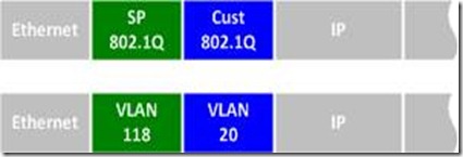
    802.1Q tunneling solves both of these issues by assigning each customer a single VLAN number, chosen by the service provider. Within each customer VLAN exists a secondary 802.1Q trunk, which is controlled by the customer. Each customer packet traversing the service provider network is tagged twice: the inner-most 802.1Q header contains the customer-chosen VLAN ID, and the outer-most header contains the VLAN ID assigned to the customer by the service provider.

    clip_image004

    802.1Q Tunnel Configuration

    Before we get started with the configuration, we must verify that all of our switches support the necessary maximum transmission unit (MTU), 1504 bytes. We can use the command show system mtu to check this, and the global configuration command system mtu to modify the device MTU if necessary (note that a reload will be required for the new MTU to take effect).

    S1# show system mtu

    System MTU size is 1500 bytes

    S1# configure terminal

    S1(config)# system mtu 1504

    Changes to the System MTU will not take effect until the next reload is done.

    Next, we'll configure our backbone trunk to carry the top-level VLANs for customers A and B, which have been assigned VLANs 118 and 209, respectively. We configure a normal 802.1Q trunk on both ISP switches. The last configuration line below restricts the trunk to carrying only VLANs 118 and 209; this is an optional step.

    S1(config)# interface f0/13

    S1(config-if)# switchport trunk encapsulation dot1q

    S1(config-if)# switchport mode trunk

    S1(config-if)# switchport trunk allowed vlan 118,209

    S2(config)# interface f0/13

    S2(config-if)# switchport trunk encapsulation dot1q

    S2(config-if)# switchport mode trunk

    S2(config-if)# switchport trunk allowed vlan 118,209

    Now for the interesting bit: the customer-facing interfaces. We assign each interface to the appropriate upper-level (service provider) VLAN, and its operational mode to dot1q-tunnel. We'll also enable Layer two protocol tunneling to transparently carry CDP and other layer two protocols between the CPE devices.

    S1(config)# interface f0/1

    S1(config-if)# switchport access vlan 118

    S1(config-if)# switchport mode dot1q-tunnel

    S1(config-if)# l2protocol-tunnel

    S1(config-if)# interface f0/3

    S1(config-if)# switchport access vlan 209

    S1(config-if)# switchport mode dot1q-tunnel

    S1(config-if)# l2protocol-tunnel

    S2(config)# interface f0/2

    S2(config-if)# switchport access vlan 118

    S2(config-if)# switchport mode dot1q-tunnel

    S2(config-if)# l2protocol-tunnel

    S2(config-if)# interface f0/4

    S2(config-if)# switchport access vlan 209

    S2(config-if)# switchport mode dot1q-tunnel

    S2(config-if)# l2protocol-tunnel

    We can use the command show dot1q-tunnel on the ISP switches to get a list of all interfaces configured as 802.1Q tunnels:

    S1# show dot1q-tunnel

    dot1q-tunnel mode LAN Port(s)

    -----------------------------

    Fa0/1

    Fa0/3

    Now that our tunnel configurations have been completed, each customer VLAN has transparent end-to-end connectivity between sites. This packet captureshows how customer traffic is double-encapsulated inside two 802.1Q headers along the ISP backbone. Any traffic left untagged by the customer (i.e., traffic in the native VLAN 1) is tagged only once, by the service provider.

    Taken From: http://packetlife.net/blog/2010/jul/12/ieee-802-1q-tunneling/

    Other:

    Friday, October 5, 2012

    Wifi on Linux via Command Line

    Connect to a wireless network via command line


    I know, the first thing you are asking is “Why would I want to have to connect to a wireless network from the command line?” To that question I can give you a simple answer…What if you want to create a script to run that will bring up your wireless network as soon as your desktop is loaded? You could get really complex and create a start up script to load a desktop based on what wirelessaccess point you needed to join. That’s one of the beauties of Linux, if you can dream it, you can do it.
    But I am getting too far ahead of myself. Let’s get back to the basics shall we? First I am going to assume that your wireless card was detected by your distribution and has the proper drivers loaded. With that accomplished you will need to have the following tools:
    • ifconfig: Enable your wireless device.
    • iwlist: List the available wireless access points.
    • iwconfig: Configure your wireless connection.
    • dhclient: Get your IP address via dhcp.
    The first command you need to use is ifconfig. With this command you are going to enable your wireless device. Most likely your device will be called wlan0. So in order to enable this you would enter the command (as root):

    ifconfig wlan0 up

    You won’t see any feedback unless there is a problem.
    The next step is to scan for your wireless network to make sure it is available. Do this with the following command:

    iwlist wlan0 scan

    With this command you will see output like the following:

    Cell 01 - Address: 00:21:43:4E:9B:F0
    ESSID:"HAIR STROBEL"
    Mode:Master
    Channel:5
    Frequency:2.432 GHz (Channel 5)
    Quality=100/100? Signal level:-45 dBm? Noise level=-95 dBm
    Encryption key:on
    IE: WPA Version 1
    Group Cipher : TKIP
    Pairwise Ciphers (1) : TKIP
    Authentication Suites (1) : PSK
    IE: IEEE 802.11i/WPA2 Version 1
    Group Cipher : TKIP
    Pairwise Ciphers (1) : CCMP
    Authentication Suites (1) : PSK
    Bit Rates:1 Mb/s; 2 Mb/s; 5.5 Mb/s; 11 Mb/s; 22 Mb/s
    6 Mb/s; 9 Mb/s; 12 Mb/s; 18 Mb/s; 24 Mb/s
    36 Mb/s; 48 Mb/s; 54 Mb/s
    Extra:tsf=000002f1d9be01b7

    So you know this network is available. From the above output you can also see this network is employing WPA2, so you will need a passkey. If you don’t know that passkey, you are out of luck (which would be the case no matter if you were using a front end in Linux, Windows, or Mac.)

    Now it’s time to configure your connection. To do this issue the command:

    iwconfig wlan0 essid NETWORK_ID key WIRELESS_KEY

    Where NETWORK_ID is the ESSID of the network with which you want to connect and WIRELESS_KEY is the security key needed to connect to the wireless access point.

    Note: iwconfig defaults to using a HEX key. If you want to use an ascii key you will have to add the “s:” prefix to your key like so:

    iwconfig wlan0 essid NETWORK_ID key s:WIRELESS_KEY

    Now that you have your configuration set, it’s time to get an IP address with the help of dhclient. Issue the command:

    dhclient wlan0

    If no output is reported there are no errors. You should now be up and running.


    Make it a script

    Of course who wants to type out all of those commands. Instead of doing this you could create a script for this like so:

    #! /bin/bash
    ifconfig wlan0
    iwconfig wlan0 essid NETWORK_ID key WIRELESS_KEY
    dhclient wlan0

    Where NETWORK_ID is the actually essid of the network and WIRELESS_KEY is the security key for that network. Save this script with the filename wireless_up.sh and then make this script executable with the command:

    chmod u+x wireless_up.sh

    You can make this a global command by placing this script in /usr/local/bin. You can now issue the command wireless_up.sh from anywhere in your directory structure and it will run, connecting you to the configured wireless access point.

    If you frequent many wireless access points you can create a script for each one giving them each unique names. By doing this, when you need to connect to a specific access point, just run the script associated with that access point and you’re good to go.

    Taken From: http://www.ghacks.net/2009/04/14/connect-to-a-wireless-network-via-command-line/

    Saturday, September 22, 2012

    Customized Windows 7 (RT Se7en Lite and AIK)

    How To Create a Customized Windows 7 Installation Disc With Integrated Updates

    image

    Do you want to save time when installing Windows 7? You can create a customized installation disc and have it perform an installation without asking you questions, integrate updates and drivers, tweak Windows, and remove Windows components.

    We’ll be using RT Se7en Lite for this – if you’ve used nLite with Windows XP or vLite with Windows Vista in the past, it works similarly. RT Se7en Lite is a sort of vLite or nLite for Windows 7.

    Image Credit: bfishadow on Flickr

    What You’ll Need

    To do this, you’ll need Windows 7 installed on your computer. You’ll also need to download and install the Windows Automated Installation Kit (WAIK) for Windows 7 from Microsoft – RT Se7en Lite is a more user friendly frontend to WAIK.

    WAIK is 1.7 GB, so the download may take a while if you have a slow Internet connection. After downloading it, extract it with a file extraction program such as 7-Zip.

    Run the StartCD.exe file, select Windows AIK Setup, and follow the instructions on your screen to install Windows AIK.

    You’ll also need a Windows 7 installation source – either a physical disc or ISO file.

    Next, download and install RT Se7en Lite from here – it’s free and donation-supported. Download the appropriate version for your version of Windows — x86 if you’re using a 32-bit version of Windows or x64 if you’re using a 64-bit edition.

    Using RT Se7en Lite

    First, click the Browse button and provide your Windows 7 files – if you have an ISO file on your hard drive, click Select ISO file and navigate to it. If you have a Windows disc, insert the disk, click Select OS path, and navigate to the disc.

    If you provide an ISO, you’ll have to specify an extraction path where the ISO’s files will be extracted to – you’ll need several gigabytes of space on your hard disk for this.

    The files will be automatically extracted after you provide your ISO.

    After selecting the edition of Windows 7 you’re customizing, RT Se7en Lite will load the image. If you have a Windows 7 disc without Service Pack 1 integrated, click the Slipstream Service Pack option in the “Select an image to configure” window and you’ll be able to integrate SP1.

    Click over to the Task pane and select the tasks you want to perform after the image is loaded. You can manually check the check boxes or select a preset. Selecting one of the check boxes will activate the corresponding configuration pane at the left side of the window.

    The integration pane allows you to integrate Windows updates, drivers, language packs, and even third-party applications into your installation disc. To integrate updates, you’ll have to download their installer files and load them into RT Seven Lite with the Add button.

    On the Features Removal or Components tab, you can permanently remove components from your Windows installation disc and control which Windows features are installed by default. For example, you can remove the included games from your Windows installer disc, or force Windows to install the IIS web server by default.

    The Tweaks tab allows you to customize the default settings for the Windows Control Panel, Desktop, Explorer, and a variety of other Windows components. You can even add custom registry settings to tweak other settings that aren’t present in the list.

    The Unattended section allows you to create an unattended installation disc – you provide answers to installation questions beforehand and Windows will install without asking you these questions during the installation process.

    For example, you can enter your product key ahead of time so Windows won’t ask you for it. The other tabs allow you to control other settings – for example, selecting the hard disks that Windows will install on. If you complete enough of these settings, Windows will install automatically without asking you any questions during the installation, allowing you to perform an unattended Windows installation.

    The Customization pane allows you to add custom screensavers, wallpapers, themes, documents, and even logon screens to your Windows 7 disc.

    On the ISO Bootable pane, you can create a ISO image from your customized installation disc. You can also burn it to a DVD or copy it to a bootable USB drive.

    RT Se7en Lite’s developers recommend booting your custom Windows 7 image in a virtual machine and installing it in the virtual machine before you use it on a physical computer, just to make sure everything is working properly.

    You can use VirtualBox or VMware Player to do this – both are free.