Saturday, November 30, 2013

Linux – Start / Stop Services (Boot + Runlevel)

How-To: Managing services with update-rc.d

Linux services can be started, stopped and reloaded with the use of scripts stocked in /etc/init.d/.

However, during start up or when changing runlevel, those scripts are searched in /etc/rcX.d/ where X is the runlevel number.

This tutorial will explain how one can activate, deactivate or modify a service start up.

When installing a new service under debian, the default is to enable it. So for instance, if you just installed apache2package, after you installed it, apache service will be started and so will it be upon the next reboots.

If you do not use apache all the time, you might want to disable this service from starting up upon boot up and simply start it manually when you actually need it by running this command:

# /etc/init.d/apache2 start

As you can see in the output below, the scripts are in init.d but the boot process executes the scripts on rcX.d (X is the runlevel), so we have symbolic links in rcX.d that point to the scripts on init.d. For something, not to be exectuted at boot, we have to destroy the symbolic links at rcX.d, this can either be done manually or via the update-rc.d  

You could either disable this service on boot up by removing manually, any symbolic links in /etc/rcX.d/SYYapache2 or by using update-rc.d.

The advantage of using update-rc.d is that it will take care of removing/adding any required links to /etc/init.d automatically.
Taking apache2 as an example, let’s examine how /etc/rcX.d is looking like:

# ls -l /etc/rc?.d/*apache2
lrwxrwxrwx 1 root root 17 2007-07-05 22:51 /etc/rc0.d/K91apache2 -> ../init.d/apache2
lrwxrwxrwx 1 root root 17 2007-07-05 22:51 /etc/rc1.d/K91apache2 -> ../init.d/apache2
lrwxrwxrwx 1 root root 17 2007-07-05 22:51 /etc/rc2.d/S91apache2 -> ../init.d/apache2
lrwxrwxrwx 1 root root 17 2007-07-05 22:51 /etc/rc3.d/S91apache2 -> ../init.d/apache2
lrwxrwxrwx 1 root root 17 2007-07-05 22:51 /etc/rc4.d/S91apache2 -> ../init.d/apache2
lrwxrwxrwx 1 root root 17 2007-07-05 22:51 /etc/rc5.d/S91apache2 -> ../init.d/apache2
lrwxrwxrwx 1 root root 17 2007-07-05 22:51
/etc/rc6.d/K91apache2 -> ../init.d/apache2

As you can see, for runlevels 0, 1 and 6 there is a K (aka Kill) at the beginning of the link, for runlevels 2, 3, 4 and 5, there is a S (aka Start). Those two letters stands for Kill and Start.
On Debian and Ubuntu, runlevels 2, 3, 4 and 5 are multi-users runlevels.

- Runlevel 0 is Halt.
- Runlevel 1 is single user mode
- Runlevel 6 is reboot

1. Removing a Service

If you want to totally disable apache2 service by hand, you would need to delete every single link in /etc/rcX.d/. Using update-rc.d it is as simple as:

# update-rc.d -f apache2 remove

The use of -f is to force the removal of the symlinks even if there is still /etc/init.d/apache2.

Note: This command will only disable the service until next time the service is upgraded. If you want to make sure the service won’t be re-enabled upon upgrade, you should also type the following:

# update-rc.d apache2 stop 80 0 1 2 3 4 5 6 .

2. Adding a service

2.1. Default priorities

Now, if you want to re-add (enable) this service to be started on boot up, you can simply use:

# update-rc.d apache2 defaults

Adding system startup for /etc/init.d/apache2 …
/etc/rc0.d/K20apache2 -> ../init.d/apache2
/etc/rc1.d/K20apache2 -> ../init.d/apache2
/etc/rc6.d/K20apache2 -> ../init.d/apache2
/etc/rc2.d/S20apache2 -> ../init.d/apache2
/etc/rc3.d/S20apache2 -> ../init.d/apache2
/etc/rc4.d/S20apache2 -> ../init.d/apache2
/etc/rc5.d/S20apache2 -> ../init.d/apache2

2.2. Custom priorities

But as you can see, the default value is 20 which is pretty different than 91 … a S20 link is started before a S91 and K91 is kill before K20.
To force apache2 to be started with priorities 91 for both Start and Kill, we need to use the following command:

# update-rc.d apache2 defaults 91

Adding system startup for /etc/init.d/apache2 …
/etc/rc0.d/K91apache2 -> ../init.d/apache2
/etc/rc1.d/K91apache2 -> ../init.d/apache2
/etc/rc6.d/K91apache2 -> ../init.d/apache2
/etc/rc2.d/S91apache2 -> ../init.d/apache2
/etc/rc3.d/S91apache2 -> ../init.d/apache2
/etc/rc4.d/S91apache2 -> ../init.d/apache2
/etc/rc5.d/S91apache2 -> ../init.d/apache2

2.3. Different priorities for Start and Kill

Alternatively, if you want to set different priorities for Start and Kill, let say Start with 20 and Kill with 80, you will need to run:

# update-rc.d apache2 defaults 20 80

Adding system startup for /etc/init.d/apache2 …
/etc/rc0.d/K80apache2 -> ../init.d/apache2
/etc/rc1.d/K80apache2 -> ../init.d/apache2
/etc/rc6.d/K80apache2 -> ../init.d/apache2
/etc/rc2.d/S20apache2 -> ../init.d/apache2
/etc/rc3.d/S20apache2 -> ../init.d/apache2
/etc/rc4.d/S20apache2 -> ../init.d/apache2
/etc/rc5.d/S20apache2 -> ../init.d/apache2

3. Specifying custom runlevels

Finally, if you only want to Start and Kill on specific runlevels, like for instance starting apache with priority 20 on runlevels 2, 3, 4 and 5 and Kill with priority 80 on runlevels 0, 1 and 6:

# update-rc.d apache2 start 20 2 3 4 5 . stop 80 0 1 6 .

Adding system startup for /etc/init.d/apache2 …
/etc/rc0.d/K80apache2 -> ../init.d/apache2
/etc/rc1.d/K80apache2 -> ../init.d/apache2
/etc/rc6.d/K80apache2 -> ../init.d/apache2
/etc/rc2.d/S20apache2 -> ../init.d/apache2
/etc/rc3.d/S20apache2 -> ../init.d/apache2
/etc/rc4.d/S20apache2 -> ../init.d/apache2
/etc/rc5.d/S20apache2 -> ../init.d/apache2

Or, to start with priority 20 for runlevel 2, 3 and 4 and priority 30 for runlevel 5 and kill with priority 80 for runlevel 0, 1 and 6:

# update-rc.d apache2 start 20 2 3 4 . start 30 5 . stop 80 0 1 6 .

Adding system startup for /etc/init.d/apache2 …
/etc/rc0.d/K80apache2 -> ../init.d/apache2
/etc/rc1.d/K80apache2 -> ../init.d/apache2
/etc/rc6.d/K80apache2 -> ../init.d/apache2
/etc/rc2.d/S20apache2 -> ../init.d/apache2
/etc/rc3.d/S20apache2 -> ../init.d/apache2
/etc/rc4.d/S20apache2 -> ../init.d/apache2
/etc/rc5.d/S30apache2 -> ../init.d/apache2

Based On: http://www.debuntu.org/how-to-managing-services-with-update-rc-d/

Raspberry Pi – Specs and Features (Summary)

This is not an howto or a project per se, but it will definitly be reference in upcoming howto’s and projects.
image

What I present here is a summary of the Raspberry Pi specs and features:

Model A 
- 256MB RAM
- one USB port
- no Ethernet 
- Power: 500 mA  model

Model B
  - 512MB RAM
  - 2 USB ports
  - Ethernet port
  - Power: 700-1000mA

Model A&B
- Main Specs
   - 700 Mhz (Most devices will run happily at 800MHz)
   - 8 dedicated GPIO pins
   - UART (Rs232)
   - i2c bus
   - SPI bus with two chip selects (also in arduino)
   - i2s audio
   - Power - 3v3, 5v, and ground.
   - If you dont use UART, i2c, etc (and use all for GPIO)
      - Revision 1 - 17 GPIOs
      - Revision 2 - 21 GPIOs.
   - GPIOs can theoretically be expanded indefinitely by I2C or SPI bus.
 
- Physical     - Measures 85.60mm x 56mm x 21mm
    - It weighs 45g.

- Network
    - 100 Mbps (model B only)
    - Ethernet is attached via the USB 2.0 bus (Gigabit not possible)
    - No netbooting or pxe
   
 - Power
    - Tension: 4,75 Volts - 5,24 Volts (You can test it on the TP2 and TP1 contacts)
    - Maximum Power - 1 Amp (1000 mA)
    - GPIO pins can draw 50mA safely (all)
    - Individual GPIO pin can only safely draw 16mA
    - Camera module requires 250mA
    - Keyboards and mice can take as little as 100mA or over 1000mA!!! (be aware, and chose low power keyboards an mice)

- Video       
   - Raspberry Pi can record and play h.264 (mp4/mkv)    
   - Two additional codecs can be purchased (RBPi Store):
      - MPEG-2 - DVDs Codec
      - VC-1     - BlueRay Codec (Microsoft format - Blu-ray discs, Windows Media, Slingbox, and HD-DVDs)

- No real time clock (RTC)

- Camera Board (Omnivision 5647)
    - Is the only camera module that is compatible
    - Connects via the CSI-2 camera port using short ribbon cable
    - The  ribbon cable can be up to 4 meters
    - Connects to the Image System Pipeline (ISP)
    - Camera module (Omnivision 5647) specs are:
       - Photo - 5MP (2592×1944 pixels)
       - Video - 1080p 30Fps 1920x1080x30fps)
       - Power - 250mA

Based On: http://www.raspberrypi.org/faqs#introShares

Raspberry Pi Remote Desktop - via VNC (TightVNC)

So you’ve got your Raspberry Pi setup, but what if you don’t have a dedicated monitor to use with it (for example, mine’s connected to my TV). How can you use it without disrupting your setup? VNC (Virtual Network Computing) allows you to see your Pi’s desktop and control it remotely using another computer running Mac OS X, Windows or Linux (and other devices too).

The VNC server software runs on your RPi, access it by running VNC client software on your other device.

The VNC Server

There are various guides for this online, most suggest using the TightVNC server software, here’s my summarised need to know version, run all commands from the command line:

  1. Install tight VNC: “sudo apt-get install tightvncserver
  2. Run the program: “tightvncserver”, and it will start a new session with 1024x728 and 24 bit colour:

pi@raspberrypi ~ $ sudo tightvncserver

New 'X' desktop is raspberrypi:1

Starting applications specified in /root/.vnc/xstartup
Log file is /root/.vnc/raspberrypi:1.log

the :1 (aka session number) means port 5901

      • If you  run the program: “tightvncserver” again, and it will start a another session with 1024x728 and 24 bit colour:

pi@raspberrypi ~ $ sudo tightvncserver

New 'X' desktop is raspberrypi:2

Starting applications specified in /root/.vnc/xstartup
Log file is /root/.vnc/raspberrypi:2.log

the :2 (aka session number) means port 5902

      • If you  want to start a custom VNC session:vncserver :3 -geometry 640x480 -depth 24

vncserver :3 -geometry 640x480 -depth 24

New 'X' desktop is raspberrypi:3

Starting applications specified in /home/pi/.vnc/xstartup
Log file is /home/pi/.vnc/raspberrypi:3.log

the :3 (aka session number) means port 5903

Notes:

  • Configure the session’s resolution after the -geometry argument. In the above 1024x768 is used. The RPi is capable of full HD so you could try 1920x1080.
  • Colour depth is specified by the -depth argument. In the above exampe, 24-bit colour depth is used. You could use 16-bit instead to reduce network traffic.
  • You can start more than one VNC session by running subsequent vncserver commands, just increment the first digit: e.g “vncserver :2 …” for a second, ”vncserver :3 …” for a third (I don’t know how many the RPi could handle).
  • You can set this to run at start up, see the eLinux wiki tutorial, or look for a later post on this blog on automatic login which can start the VNC session with less effort.

The VNC Server (Connect To Your Raspberry PI)

There are lots of VNC clients you can use, depending on your platform. I’m using Apple’s Remote Desktop software which is incredibly powerful (especially when administering Macs) but is overkill if you are just using it with your RPi. TightVNC has a free client application, there’s a native Windows version and a surprisingly good (but limited) Java version, which should run on any desktop/laptop system. A Google search should find you a suitable app for your own system.

To connect to your RPi:

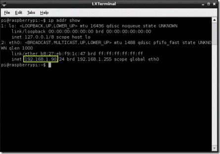
  1. Get your RPi’s IP address by running “ip addr show” or “ifconfig”. The IP address with be shown as highlighted in the image below.
  2. Connect your client to the IP address obtained from 1.
  3. Use port “590x”, where “x” is the session number seen in the previous section. If this doesn’t work, enter the IP address followed by “:x”, e.g. “192.168.1.50:1” (works on TigthVNC).

clip_image002

Based On: http://gettingstartedwithraspberrypi.tumblr.com/post/24142374137/setting-up-a-vnc-server

Monday, November 18, 2013

Make a Cisco Unified Communication Manager Bootable ISO

How to make Cisco Unified Communication Manager bootable ISO from non-bootable image on Linux

NOVEMBER 18, 2013

Here are the exact steps that help you to make bootable CUCM ISO image from non-bootable ISO image on Linux. If you want to do the same on Windows I strongly recommend to read this tutorial. I could not write my tutorial without reading it first.

Introduction
Typically, non-bootable CUCM images are those available for download on Cisco website. I used Linux Fedora 17 and mkisofs to create bootable CUCM ISO image but feel free to use any Linux distro with genisoimage installed. On Fedora you have to install a package genisoimage to get mkisofs installed.

Used software
Linux Fedora 17 x86-64 with installed genisoimage utility
CUCM 9.1.2 - UCSInstall_UCOS_9.1.2.10000-28.sgn.iso

1. Install genisomage

$ sudo yum install genisomage

Create directory where non-bootable CUCM ISO image will be mounted.

$ mkdir -p ~/temp/extract

2. Create directory where the content of mounted non-bootable ISO image will be copied

$ mkdir -p ~/temp2/

3. Mount non-bootable DVD ISO image

$ sudo mount -t iso9660 ~/Downloads/UCSInstall_UCOS_9.1.2.10000-28.sgn.iso ~/temp/extract

4. Copy the content of mounted ISO image to directory ~/temp2

$ cp -rv ~/temp/extract/ ~/temp2

5.  Create bootable ISO image

cd ~/temp2/extract

mkisofs -o ../UCSInstall_UCOS_9.1.2.10000-28.sgn-bootable.iso -R -no-emul-boot -boot-load-size 32 -boot-info-table -b isolinux/isolinux.bin .

End.

Reference
http://htluo.blogspot.co.uk/2010/04/how-to-make-non-bootable-iso-image.html
http://www.ipcommute.co.uk/technical-articles/17–creating-isolinux-boot-dvds-with-free-software-cucm-uccx-cups.html


Taken From: http://brezular.wordpress.com/2013/11/18/how-to-make-cisco-unified-communication-manager-bootable-iso-from-non-bootable-image-on-linux/

Saturday, November 16, 2013

Stresslinux – Torture Tests to Your Hardware

Stresslinux Torture-Tests Your Hardware

Stresslinux is a lean, mean torture machine with 750MB of hardware-pummeling goodness for probing and load-testing your computer's hardware. Why, you ask, would anyone want to torture their nice hardware? Perhaps "torture" isn't the best word; think load-testing to expose defects, "burning in" a new machine, or to figure out some limits for overclocking.

Stresslinux runs from external bootable media: CD, USB stick, PXE boot, or you can run the VMWare image. My favorite is a USB stick because it is fast. There are good instructions for creating your chosen boot medium.

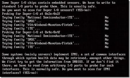
When you boot up, you have the option to allow sl-wizard to probe your system for sensors and then load the appropriate drivers (see the screen shot, below).

clip_image001

Probing system sensors at boot.

You can re-run this anytime after boot by deleting /tmp/sensors and then running the sl-wizard.sh script as root, like this:

Exploring Stresslinux

This is not your ordinary stripped-down Linux. It was built with SUSE Studio, and is based on OpenSUSE. If you like playing with test builds there are a ton of 'em.

Stresslinux uses Busybox in place of the usual coreutils, fileutils, and other standard Linux commands. Busybox is a single stripped-down binary containing several dozen commands, and it uses the ash shell, so you may find that some of your favorite options are missing. The Busybox command reference should help you.

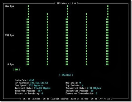
Stresslinux uses the Fn keys in an interesting way. There are 6 ordinary ttys on F1-F6, and it boots to tty1 on F1. The rest are normal login ttys. On US keyboards you can switch between these with ALT+Fn. (STRG+Fn on German keyboards, which is the same as CTRL+Fn.) F10 displays eth0 throughput (see above), F11 shows hard disk temperatures, and F12 displays lm-sensors readings.

clip_image002

Probing system sensors at boot.

That Was Fun, Now What?

Now that Stresslinux is booted up and you have gazed upon your eth0 and sensor outputs, what's next? Let's spend some time with the stress command, because that is a good general-purpose workload generator. It operates by siccing a bunch of hogs on your system. This simple invocation puts a light load on the CPU, I/O, memory, and hard drive:

  • > stress --cpu 8 --io 4 --vm 2 --hdd 4 --timeout 30s --verbose
  • stress: info: [16275] dispatching hogs: 8 cpu, 4 io, 2 vm, 4 hdd
  • stress: dbug: [16275] using backoff sleep of 54000us
  • stress: dbug: [16275] setting timeout to 10s
  • stress: dbug: [16275] --> hogcpu worker 8 [16276] forked
  • stress: dbug: [16275] --> hogio worker 4 [16277] forked
  • stress: dbug: [16275] --> hogvm worker 2 [16278] forked
  • stress: dbug: [16275] --> hoghdd worker 4 [16279] forked
  • stress: dbug: [16275] using backoff sleep of 42000us
  • stress: dbug: [16275] setting timeout to 10s
  • [...]
  • stress: info: [16275] successful run completed in 13s

That snippet shows I wasn't kidding about the hogs. When it finishes with "successful run completed" that means there were no errors. If it did detect errors, it would either try to tell you what they were, or tell you to examine the syslog. Let's walk through this so we know what it's doing.

--cpu 8 tells it to fork 8 processes. Each process calculates the square root of a random number (by calling the sqrt() and rand functions) in a loop that stops at the end of your timeout, or when you stop it with CTRL+c. Are there any geezers out there who remember who said "Computer. Compute to the last digit the value of pi?" And why? This is similar, a way to keep the CPU constantly busy.

--io 4 forks 4 processes that call the sync() function in a loop. sync() flushes any data buffered in memory to disk. Most Linux filesystems use delayed allocation; that is, data are held in memory for a period of time before being written to disk. This speeds up performance because disk I/O is slower than RAM. Running this one by itself and trying out different values will give you an idea of your I/O performance.

--vm 2 thrashes your RAM by forking 2 processes to allocate and release memory. (Looping malloc() and free().)

--hdd 4 pummels your hard drive with writes, by calling the write function in a loop.

--timeout 30s tells stress to stop after 30 seconds. Or whatever time you want, of course, using s,m,h,d,y (seconds, minutes, hours, days, years). Always set a timeout, because this is your protection from the system locking up and becoming inaccessible. stress runs in userspace and can't cause any damage, but it would be sad to have to reboot to stop it.

--verbose makes it spit out many lines telling what it is doing.

The example above is pretty wimpy and won't stress out anything made after 1990. You can run one test at a time, for example. This puts a much larger load on your CPU:

> stress --cpu 2000 --timeout 30s --verbose

Just for fun, follow along with top, and press 1 to see all cores individually:

  • top - 18:58:17 up 8:56, 9 users, load average: 419.86, 226.40, 88.02
  • Tasks: 2207 total, 1449 running, 756 sleeping, 0 stopped, 2 zombie
  • Cpu0 :100.0%us, 0.0%sy, 0.0%ni, 0.0%id, 0.0%wa, 0.0%hi, 0.0%si, 0.0%st
  • Cpu1 : 98.1%us, 1.6%sy, 0.0%ni, 0.0%id, 0.0%wa, 0.0%hi, 0.3%si, 0.0%st
  • Cpu2 : 97.7%us, 2.3%sy, 0.0%ni, 0.0%id, 0.0%wa, 0.0%hi, 0.0%si, 0.0%st
  • When your stress run is finished, notice the difference in the Tasks statistics and load averages.

You can control the load on your memory with the --vm-bytes option. Suppose you have 8GB memory, which is not unusual in these here modern times. Try this:

> stress --vm 2 --vm-bytes 6G --timeout 30s --verbose

Be careful with this because thrashing your memory can make your system hang. The vm option allocates and releases memory; the vm-hang simulates low memory conditions by having each hog process go to sleep, rather than releasing memory. This example hogs 3 gigabytes of memory:

> stress --vm 2 --vm-bytes 3G --vm-hang --timeout 60s

What happens when your system is I/O bound? Try this:

> stress --io 8 --timeout 2m

Test your hard drive by writing a large file to disk:

> stress --hdd 1 --timeout 5m

The default file size is 1GB, and you can specify any size with the --hdd-bytes option, for example --hdd-bytes 5G writes a 5 gigabyte file.

stress is tidy and cleans up after itself, so you shouldn't have to worry about leftover hogs running amok. The documentation on stress isn't exactly lavish, and the most complete help is in info stress.

Other Commands

Visit the Stresslinux software page to see all of its system-testing commands. It includes reliable standbys like CPU burn, memtest, bonnie++, lshw (list system hardware, my fave), tiobench, and smartmontools. There are a lot of nice Linux bootable system rescue distros that do this and that and everything, but I think Stresslinux is tops for a good specialized distro.

Taken From: https://www.linux.com/learn/tutorials/613523:stresslinux-torture-tests-your-hardware

Thursday, November 14, 2013

Serial Port (RS232) - Null Modem / Straight Through

The Difference Between a Null Modem and Straight Through Serial Cable

Hardware: Serial

Problem:
I would like to use my computer's built-in serial port to communicate with a serial device, and I have both the null modem and straight through serial cables. What is the difference between the two cables, and which one should I use?

Solution:
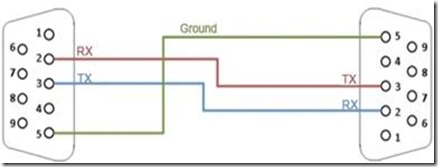
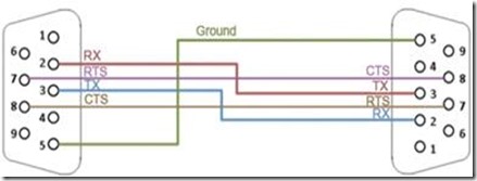
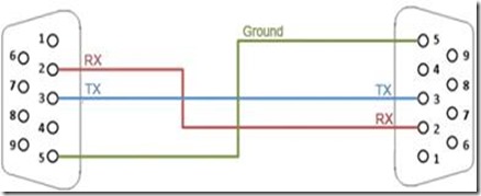
The null modem cable is frequently called a crossover cable. It is used to allow two serial Data Terminal Equipment (DTE) devices to communicate with each other without using a modem or a Data Communications Equipment (DCE) device in between. For this to happen, the Transmit (TXD) pin of one device needs to be connected to the Receive (RXD) pin of the other device.  To enable handshaking between the two devices, the Request to Send (RTS) pin of one device must be connected to the Clear to Send (CTS) pin of the other device. Because these pins are "crossed" on the two cable terminals, the name crossover cable is used.

Simple Null Modem Cable

clip_image004

Null Modem Cable with Handshaking

clip_image006

A straight-through cable is used to connect a DTE device to a DCE device. The TXD-RXD and RTS-CTS pins are not cross-connected in this case, hence the term straight through cable.

Simple Straight Through Cable

clip_image008

The built-in serial port on a PC is a DTE device. Modems and printers are examples of DCE devices.  Note that an instrument with serial interface could be either a DTE or a DCE device.  It is best to check the user manual of the instrument to find out the device type.  For more information regarding DTE and DCE devices, please see the links below.
To tell if your cable is null modem or straight though, you can search the part number at ni.com, the product description will tell if it is null modem. Alternatively you can use a hand held DMM to test continuity on the individual pins of your serial cable. If every pin is electrically connected to the corresponding pin on the other end, i.e.: pin 1 to pin1, pin 2 to pin 2, etc. then the cable is straight through.


Related Links:
Products and Services: Serial Interfaces
KnowledgeBase 1TU953QR: What Do DTE and DCE Mean in Serial Communication?
Developer Zone Tutorial: Serial Communication General Concept

Attachments:

Report Date: 22/12/2004
Last Updated: 18/06/2010
Document ID: 3GLDMSIT

Taken From: http://digital.ni.com/public.nsf/allkb/1EE0DD8AF67922FA86256F720071DECF

Sunday, November 10, 2013

Make Your own PoE - Injector and Splitter

Make your own Power Over Ethernet Injector set for $2 in Parts

clip_image001

Ever need to install a network hub, camera, or other device in a location that did not have a locally available power outlet? Need to ‘extend’ the power cord?

In this tutorial, we’ll be building a very cheap Power Over Ethernet Injector out of $2 in parts. This will let you place your power supply for your device near the ethernet hub, where power is plentiful, and place the device itself hundreds of feet away.

Caveat: There is a Power Over Ethernet (POE) standard, which we’re ignoring, as this particular injector setup is for legacy products that do not offer POE support.

The standart states the minumum power supply should be:

  • 44V DC / 350mA = 15.4 Watts

so for standart compatibility (802.3af - PSE Mid-Span) you would have to use a 48V DC power supply with equal or more than 350mA.

In my case, I’m making it for my wired network camera, a Hawking HNC-210, which is generally alwayssituated farther away from the power outlet. It comes with a fairly short (6′) power cable, which is an odd product design consideration. Since you’d generally put a camera at eye-level or higher, this cable is really too short for most installs.

Parts List: $1.80 US:

  • 1. RJ-45 pass-thru connector 80¢
  • 2. 2.1mm power jack and plug 50¢
  • 3. spare (short) working ethernet cable 50¢

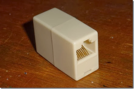
The first item we need is an ethernet (RJ-45) pass-thru connector, for patching 2 ethernet cables end to end. It is available at many local retailers/computer shops. I grabbed a few at BG Micro for 80¢ a piece. The nice thing about these is you’re getting 2 pre-wired RJ-45 connectors for very cheap.

clip_image003

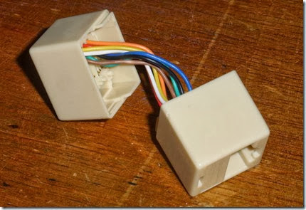
A bit of man-handling to pry the two halves apart, and we have 2 halves of our POE injector. Simply cut all 8 wires at the half way point. You can tell which wire goes to which pin by looking at the inside of the now disassembled connector. Take notes of which wire goes to which pin, using a regular ethernet cable as a reference. There are 8 wires, which we need to be grouped. 4 wires are for ethernet, 2 wires for Positive Power, and 2 wires for Negative Power (Ground).

clip_image004

You’ll need to strip and tin all the ends of each tiny wire on both pieces. We’re basically hand-wiring connections for power and ethernet in each connector. Use the wiring table later in this article to make the connections. While you’re here, why not put some shrink tubing over each wire to protect them from cross-connection later.

I need more Power, Scotty!

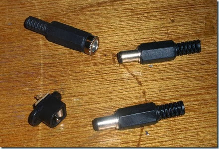
Next up in the arsenal, we need the power jacks to pass the power from the AC wall wart to the camera. I checked the camera, and it used a standard 2.1mm power jack. I picked up 2 example jacks from an electronics supplier.

clip_image005

The top set is an inline jack and plug, which costs $1.20 for the set. The bottom set is an panel mount jack and plug, which costs considerably less, at only 50¢ for the set. First, check to make sure they work together.

clip_image006

I soldered 2 wires to the power plug that were equal length to the ethernet dongle I already had on hand. I slipped some shrink tubing over it, then made the connections.

With the Power Connections, polarity doesn’t matter as much as making sure you don’t flip the circuit with your cable build. If you decide blue is tip and brown is ground, stick with it at both ends of the injectors – not following this is a sure way of destroying the device you’re powering.

In my case, I connected the tip of the power plug to BOTH the 2 blue wires, and the shield to BOTH the 2 brown wires. On the other side, I connected the same to the tiny panel-mount power jack. I then used hot-melt glue to mount the panel mount to the remaining plastic frame.

Why connect to both wires? In case one wire fails in a regular ethernet cable, it’ll still work. Plus, there is less voltage loss with the larger combined wire. The total voltage loss is negligible for most installs. If you find your device isn’t working properly, check to see if the cable is too long, and the voltage is too low to power the device.

Next up the complex ethernet wiring….

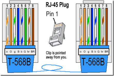
Common straight-through ethernet cables only use 4 wires out of the 8 inside the sheathing. The common wiring in illustrated below.

clip_image007

Take your short working ethernet cord and cut it in half. You’ll want 2 short 8″ pieces, with the working ethernet RJ-45 ends still attached. Strip off an inch at the cut end, and expose the 8 wires inside. Cut the blue and brown sets of wires off. These are unused in this application – these ‘dongles’ will be the ethernet in and out connections.

image

So the ethernet wires (in most cases, you should check) that we’ll be using to pass the ethernet traffic is the 2 orange wires and the 2 green wires, which fall on pins 1, 2, 3 and 6. Simply connect the pin 1 on the ethernet dongle to pin 1 on the ethernet connector jack, and so on through the other 7 wires on both sides.

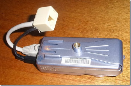
Finished Power Over Ethernet Injector and Splitter

image

I covered open connections with shrink tubing, then tucked all wires inside the tiny connector cases. I then used hot-melt glue to seal up the open ends of the connectors, and now I have a matched pair of Power Over Ethernet Injectors!

Installed at the Camera End

clip_image025

Simply attach one end of your 100+ foot long ethernet cable to this end, place your camera anywhere, with only one cable feeding to it.

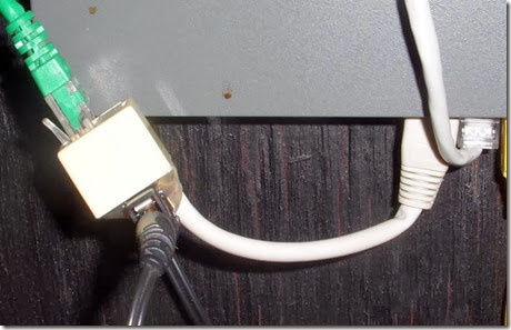
Installed at Hub/Switch End

clip_image026

At the other end, at the switch/hub (also suitably close to a power outlet), simply plug it into an available port, plug in the power supply, then the camera feed line.

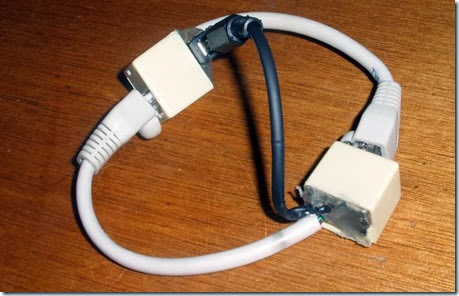
Shield your eyes! Cable Porn! Shocking double-69 cable-on-cable action!

clip_image027

Based On: http://underdesign.wordpress.com/2010/04/07/make-your-own-power-over-ethernet-injector/

PoE Standart Details: http://www.ieee.li/pdf/viewgraphs/introduction_to_poe_ieee802.3af_802.3at.pdf

Monday, November 4, 2013

Linux Swap Space – All You Need to Know

All about Linux swap space

By Gary Sims

Linux divides its physical RAM (random access memory) into chucks of memory called pages. Swapping is the process whereby a page of memory is copied to the preconfigured space on the hard disk, called swap space, to free up that page of memory. The combined sizes of the physical memory and the swap space is the amount of virtual memory available.

Swapping is necessary for two important reasons. First, when the system requires more memory than is physically available, the kernel swaps out less used pages and gives memory to the current application (process) that needs the memory immediately. Second, a significant number of the pages used by an application during its startup phase may only be used for initialization and then never used again. The system can swap out those pages and free the memory for other applications or even for the disk cache.

However, swapping does have a downside. Compared to memory, disks are very slow. Memory speeds can be measured in nanoseconds, while disks are measured in milliseconds, so accessing the disk can be tens of thousands times slower than accessing physical memory. The more swapping that occurs, the slower your system will be. Sometimes excessive swapping or thrashing occurs where a page is swapped out and then very soon swapped in and then swapped out again and so on. In such situations the system is struggling to find free memory and keep applications running at the same time. In this case only adding more RAM will help.

Linux has two forms of swap space: the swap partition and the swap file. The swap partition is an independent section of the hard disk used solely for swapping; no other files can reside there. The swap file is a special file in the filesystem that resides amongst your system and data files.

To see what swap space you have, use the command swapon -s. The output will look something like this:

Filename Type Size Used Priority

/dev/sda5 partition 859436 0 -1

Each line lists a separate swap space being used by the system. Here, the 'Type' field indicates that this swap space is a partition rather than a file, and from 'Filename' we see that it is on the disk sda5. The 'Size' is listed in kilobytes, and the 'Used' field tells us how many kilobytes of swap space has been used (in this case none). 'Priority' tells Linux which swap space to use first. One great thing about the Linux swapping subsystem is that if you mount two (or more) swap spaces (preferably on two different devices) with the same priority, Linux will interleave its swapping activity between them, which can greatly increase swapping performance.

To add an extra swap partition to your system, you first need to prepare it. Step one is to ensure that the partition is marked as a swap partition and step two is to make the swap filesystem. To check that the partition is marked for swap, run as root:

fdisk -l /dev/hdb

Replace /dev/hdb with the device of the hard disk on your system with the swap partition on it. You should see output that looks like this:

Device Boot Start End Blocks Id System

/dev/hdb1 2328 2434 859446 82 Linux swap / Solaris

If the partition isn't marked as swap you will need to alter it by running fdisk and using the 't' menu option. Be careful when working with partitions -- you don't want to delete important partitions by mistake or change the id of your system partition to swap by mistake. All data on a swap partition will be lost, so double-check every change you make. Also note that Solaris uses the same ID as Linux swap space for its partitions, so be careful not to kill your Solaris partitions by mistake.

Once a partition is marked as swap, you need to prepare it using the mkswap (make swap) command as root:

mkswap /dev/hdb1

If you see no errors, your swap space is ready to use. To activate it immediately, type:

swapon /dev/hdb1

You can verify that it is being used by running swapon -s. To mount the swap space automatically at boot time, you must add an entry to the /etc/fstab file, which contains a list of filesystems and swap spaces that need to be mounted at boot up. The format of each line is:

Since swap space is a special type of filesystem, many of these parameters aren't applicable. For swap space, add:

/dev/hdb1 none swap sw 0 0

where /dev/hdb1 is the swap partition. It doesn't have a specific mount point, hence none. It is of type swapwith options of sw, and the last two parameters aren't used so they are entered as 0.

To check that your swap space is being automatically mounted without having to reboot, you can run the swapoff -a command (which turns off all swap spaces) and then swapon -a (which mounts all swap spaces listed in the /etc/fstab file) and then check it with swapon -s.

Swap file

As well as the swap partition, Linux also supports a swap file that you can create, prepare, and mount in a fashion similar to that of a swap partition. The advantage of swap files is that you don't need to find an empty partition or repartition a disk to add additional swap space.

To create a swap file, use the dd command to create an empty file. To create a 1GB file, type:

dd if=/dev/zero of=/swapfile bs=1024 count=1048576

/swapfile is the name of the swap file, and the count of 1048576 is the size in kilobytes (i.e. 1GB).

Prepare the swap file using mkswap just as you would a partition, but this time use the name of the swap file:

mkswap /swapfile

And similarly, mount it using the swapon command: swapon /swapfile.

The /etc/fstab entry for a swap file would look like this:

/swapfile none swap sw 0 0

How big should my swap space be?

It is possible to run a Linux system without a swap space, and the system will run well if you have a large amount of memory -- but if you run out of physical memory then the system will crash, as it has nothing else it can do, so it is advisable to have a swap space, especially since disk space is relatively cheap.

The key question is how much? Older versions of Unix-type operating systems (such as Sun OS and Ultrix) demanded a swap space of two to three times that of physical memory. Modern implementations (such as Linux) don't require that much, but they can use it if you configure it. A rule of thumb is as follows: 1) for a desktop system, use a swap space of double system memory, as it will allow you to run a large number of applications (many of which may will be idle and easily swapped), making more RAM available for the active applications; 2) for a server, have a smaller amount of swap available (say half of physical memory) so that you have some flexibility for swapping when needed, but monitor the amount of swap space used and upgrade your RAM if necessary; 3) for older desktop machines (with say only 128MB), use as much swap space as you can spare, even up to 1GB.

The Linux 2.6 kernel added a new kernel parameter called swappiness to let administrators tweak the way Linux swaps. It is a number from 0 to 100. In essence, higher values lead to more pages being swapped, and lower values lead to more applications being kept in memory, even if they are idle. Kernel maintainer Andrew Morton has said that he runs his desktop machines with a swappiness of 100, stating that "My point is that decreasing the tendency of the kernel to swap stuff out is wrong. You really don't want hundreds of megabytes of BloatyApp's untouched memory floating about in the machine. Get it out on the disk, use the memory for something useful."

One downside to Morton's idea is that if memory is swapped out too quickly then application response time drops, because when the application's window is clicked the system has to swap the application back into memory, which will make it feel slow.

The default value for swappiness is 60. You can alter it temporarily (until you next reboot) by typing as root:

echo 50 > /proc/sys/vm/swappiness

If you want to alter it permanently then you need to change the vm.swappiness parameter in the /etc/sysctl.conf file.

Conclusion

Managing swap space is an essential aspect of system administration. With good planning and proper use swapping can provide many benefits. Don't be afraid to experiment, and always monitor your system to ensure you are getting the results you need.

Taken From: http://www.linux.com/news/software/applications/8208-all-about-linux-swap-space