Tutorial: Raspberry Pi GPIO Pins and Python
· By Mark Kleback
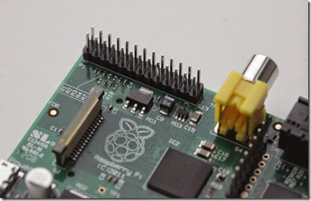
The GPIO pins on a Raspberry Pi are a great way to interface physical devices like buttons and LEDs with the little Linux processor. If you’re a Python developer, there’s a sweet library called RPi.GPIO that handles interfacing with the pins. In just three lines of code, you can get an LED blinking on one of the GPIO pins.
INSTALLATION
The newest version of Raspbian has the RPi.GPIO library pre-installed. You’ll probably need to update your library, so using the command line, run:
sudo python
import RPi.GPIO as GPIO
GPIO.VERSION
The current version of RPi.GPIO is 0.5.4 If you need to update to a newer version, run:
sudo apt-get update
sudo apt-get upgrade
If you don’t have the RPi.GPIO library because you’re using an older version of Raspbian, there are great instructions on the Raspberry Pi Spy website on installing the package from scratch.
USING THE RPI.GPIO LIBRARY
Now that you’ve got the package installed and updated, let’s take a look at some of the functions that come with it. Open the Leafpad text editor and save your sketch as “myInputSketch.py”. From this point forward, we’ll execute this script using the command line:
sudo python myInputSketch.py
All of the following code can be added to this same file. Remember to save before you run the above command. To exit the sketch and make changes, press Ctrl+C.
To add the GPIO library to a Python sketch, you must first import it:
import RPi.GPIO as GPIO
Then we need to declare the type of numbering system we’re going to use for our pins:
#set up GPIO using BCM numbering
GPIO.setmode(GPIO.BCM)
#setup GPIO using Board numbering
GPIO.setmode(GPIO.BOARD)
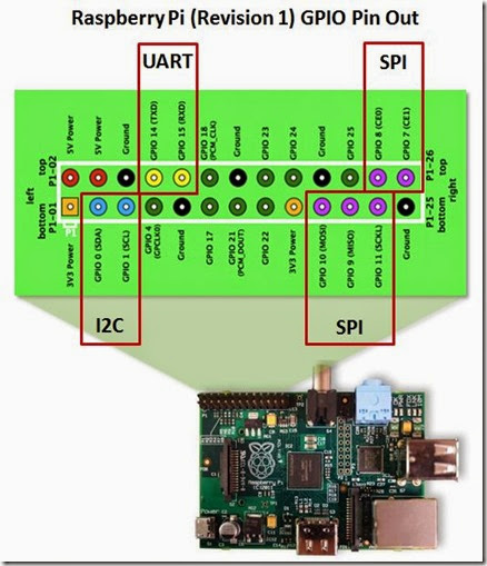
The main difference between these modes is that the BOARD option uses the pins exactly as they are laid out on the Pi. No matter what revision you’re using, these will always be the same. The BCM option uses the Broadcom SoC numbering, which differs between version 1 and version 2 of the Pi.
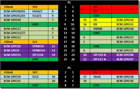
from Meltwater’s Raspberry Pi Hardware
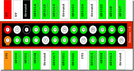
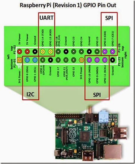
In the image above, you’ll see that Pin 5 is GPIO01/03. This means that a v.1 Pi is GPIO 01, while a v.2 Pi is GPIO 03. The BCM numbering is what I’ll be using for the rest of this entry, because it’s universal across other programming languages.
BUILDING A CIRCUIT
Now we’re going to get into inputs and outputs. In the circuit shown below, two momentary switches are wired to GPIO pins 23 and 24 (pins 16 and 18 on the board). The switch on pin 23 is tied to 3.3V, while the switch on pin 24 is tied to ground. The reason for this is that the Raspberry Pi has internal pull-up and pull-down resistors that can be specified when the pin declarations are made.
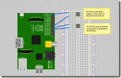
To set up these pins, write:
GPIO.setup(23, GPIO.IN, pull_up_down=GPIO.PUD_DOWN)
GPIO.setup(24, GPIO.IN, pull_up_down=GPIO.PUD_UP)
This will enable a pull-down resistor on pin 23, and a pull-up resistor on pin 24. Now, let’s check to see if we can read them. The Pi is looking for a high voltage on Pin 23 and a low voltage on Pin 24. We’ll also need to put these inside of a loop, so that it is constantly checking the pin voltage. The code so far looks like this:
import RPi.GPIO as GPIO
GPIO.setmode(GPIO.BCM)
GPIO.setup(23, GPIO.IN, pull_up_down = GPIO.PUD_DOWN)
GPIO.setup(24, GPIO.IN, pull_up_down = GPIO.PUD_UP)
while True:
if(GPIO.input(23) ==1):
print(“Button 1 pressed”)
if(GPIO.input(24) == 0):
print(“Button 2 pressed”)
GPIO.cleanup()
The indents in Python are important when using loops, so be sure to include them. You also must run your script as “sudo” to access the GPIO pins. The GPIO.cleanup() command at the end is necessary to reset the status of any GPIO pins when you exit the program. If you don’t use this, then the GPIO pins will remain at whatever state they were last set to.
THE PROBLEM WITH POLLING
This code works, but prints a line for each frame that the button is pressed. This is extremely inconvenient if you want to use that button to trigger an action or command only one time. Luckily, the GPIO library has built in a rising-edge and falling-edge function. A rising-edge is defined by the time the pin changes from low to high, but it only detects the change. Similarly, the falling-edge is the moment the pin changes from high to low. Using this definition, let’s change our code slightly:
import RPi.GPIO as GPIO
GPIO.setmode(GPIO.BCM)
GPIO.setup(23, GPIO.IN, pull_up_down = GPIO.PUD_DOWN)
GPIO.setup(24, GPIO.IN, pull_up_down = GPIO.PUD_UP)
while True:
GPIO.wait_for_edge(23, GPIO.RISING)
print(“Button 1 Pressed”)
GPIO.wait_for_edge(23, GPIO.FALLING)
print(“Button 1 Released”)
GPIO.wait_for_edge(24, GPIO.FALLING)
print(“Button 2 Pressed”)
GPIO.wait_for_edge(24, GPIO.RISING)
print(“Button 2 Released”)
GPIO.cleanup()
When you run this code, notice how the statement only runs after the edge detection occurs. This is because Python is waiting for this specific edge to occur before proceeding with the rest of the code. What happens if you try to press button 2 before you let go of button 1? What happens if you try to press button 1 twice without pressing button 2? Because the code is written sequentially, the edges must occur in exactly the order written.
Edge Detection is great if you need to wait for an input before continuing with the rest of the code. However, if you need to trigger a function using an input device, then events and callback functions are the best way to do that.
EVENTS AND CALLBACK FUNCTIONS
Let’s say you’ve got the Raspberry Pi camera module, and you’d like it to snap a photo when you press a button. However, you don’t want your code to poll that button constantly, and you certainly don’t want to wait for an edge because you may have other code running simultaneously.
The best way to execute this code is using a callback function. This is a function that is attached to a specific GPIO pin and run whenever that edge is detected. Let’s try one:
import RPi.GPIO as GPIO
GPIO.setmode(GPIO.BCM)
GPIO.setup(23, GPIO.IN, pull_up_down = GPIO.PUD_DOWN)
GPIO.setup(24, GPIO.IN, pull_up_down = GPIO.PUD_UP)
def printFunction(channel):
print(“Button 1 pressed!”)
print(“Note how the bouncetime affects the button press”)
GPIO.add_event_detect(23, GPIO.RISING, callback=printFunction, bouncetime=300)
while True:
GPIO.wait_for_edge(24, GPIO.FALLING)
print(“Button 2 Pressed”)
GPIO.wait_for_edge(24, GPIO.RISING)
print(“Button 2 Released”)
GPIO.cleanup()
You’ll notice here that button 1 will consistently trigger the printFunction, even while the main loop is waiting for an edge on button 2. This is because the callback function is in a separate thread. Threads are important in programming because they allow things to happen simultaneously without affecting other functions. Pressing button 1 will not affect what happens in our main loop.
Events are also great, because you can remove them from a pin just as easily as you can add them:
GPIO.remove_event_detect(23)
Now you’re free to add a different function to the same pin!
ADDING FUNCTIONALITY
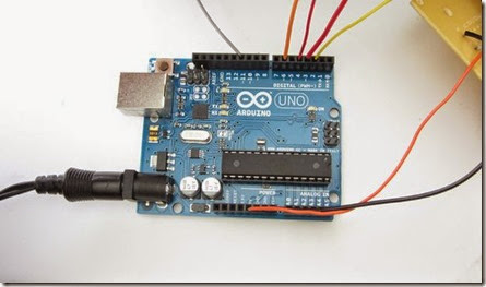
As convenient as callback functions are for the GPIO pins, it still doesn’t change the fact that the Raspberry Pi is just not ideal for analog inputs or PWM outputs. However, because the Pi has Tx and Rx pins (pins 8 and 10, GPIO 14 and 15), it can easily communicate with an Arduino. If I have a project that requires an analog sensor input, or smooth PWM output, simply writing commands to the serial port to the Arduino can make things seamless.
Taken From: http://makezine.com/projects/tutorial-raspberry-pi-gpio-pins-and-python/
![clip_image001[1] clip_image001[1]](http://lh5.ggpht.com/-b5roIZ4KuAw/U1owedmhCII/AAAAAAAAEtw/KMn9D8tC-Xo/clip_image001%25255B1%25255D%25255B3%25255D.jpg?imgmax=800)



![clip_image001[5] clip_image001[5]](http://lh4.ggpht.com/-_IN08EbcYzs/U0HoCRodhtI/AAAAAAAAEnc/_fNof2K58AI/clip_image001%25255B5%25255D%25255B4%25255D.jpg?imgmax=800)
![clip_image002[5] clip_image002[5]](http://lh3.ggpht.com/-wyDXMpWSh3w/U0HoDAvhABI/AAAAAAAAEjw/cHs2vpK7Qr8/clip_image002%25255B5%25255D%25255B3%25255D.jpg?imgmax=800)
![clip_image003[5] clip_image003[5]](http://lh5.ggpht.com/-2uZQ11nabfA/U0HoDl5B9zI/AAAAAAAAEj8/wxdZLw7I55M/clip_image003%25255B5%25255D%25255B3%25255D.jpg?imgmax=800)
![clip_image004[5] clip_image004[5]](http://lh6.ggpht.com/-uRtgqA_0IWw/U0HoERtP9TI/AAAAAAAAEkE/JwemxYkLa6c/clip_image004%25255B5%25255D%25255B3%25255D.jpg?imgmax=800)
![clip_image005[6] clip_image005[6]](http://lh5.ggpht.com/-tIDJeq3h8cI/U0HoFF8DEhI/AAAAAAAAEkM/ujDCmXhqmyU/clip_image005%25255B6%25255D%25255B3%25255D.jpg?imgmax=800)
![clip_image006[5] clip_image006[5]](http://lh3.ggpht.com/-MkbY0SvYAkI/U0HoFsQP5NI/AAAAAAAAEkU/ifUxvTStZ0E/clip_image006%25255B5%25255D%25255B4%25255D.jpg?imgmax=800)
