Sunday, November 10, 2013

Make Your own PoE - Injector and Splitter

Make your own Power Over Ethernet Injector set for $2 in Parts

clip_image001

Ever need to install a network hub, camera, or other device in a location that did not have a locally available power outlet? Need to ‘extend’ the power cord?

In this tutorial, we’ll be building a very cheap Power Over Ethernet Injector out of $2 in parts. This will let you place your power supply for your device near the ethernet hub, where power is plentiful, and place the device itself hundreds of feet away.

Caveat: There is a Power Over Ethernet (POE) standard, which we’re ignoring, as this particular injector setup is for legacy products that do not offer POE support.

The standart states the minumum power supply should be:

  • 44V DC / 350mA = 15.4 Watts

so for standart compatibility (802.3af - PSE Mid-Span) you would have to use a 48V DC power supply with equal or more than 350mA.

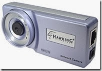
In my case, I’m making it for my wired network camera, a Hawking HNC-210, which is generally alwayssituated farther away from the power outlet. It comes with a fairly short (6′) power cable, which is an odd product design consideration. Since you’d generally put a camera at eye-level or higher, this cable is really too short for most installs.

Parts List: $1.80 US:

  • 1. RJ-45 pass-thru connector 80¢
  • 2. 2.1mm power jack and plug 50¢
  • 3. spare (short) working ethernet cable 50¢

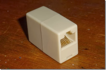
The first item we need is an ethernet (RJ-45) pass-thru connector, for patching 2 ethernet cables end to end. It is available at many local retailers/computer shops. I grabbed a few at BG Micro for 80¢ a piece. The nice thing about these is you’re getting 2 pre-wired RJ-45 connectors for very cheap.

clip_image003

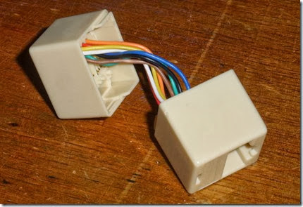
A bit of man-handling to pry the two halves apart, and we have 2 halves of our POE injector. Simply cut all 8 wires at the half way point. You can tell which wire goes to which pin by looking at the inside of the now disassembled connector. Take notes of which wire goes to which pin, using a regular ethernet cable as a reference. There are 8 wires, which we need to be grouped. 4 wires are for ethernet, 2 wires for Positive Power, and 2 wires for Negative Power (Ground).

clip_image004

You’ll need to strip and tin all the ends of each tiny wire on both pieces. We’re basically hand-wiring connections for power and ethernet in each connector. Use the wiring table later in this article to make the connections. While you’re here, why not put some shrink tubing over each wire to protect them from cross-connection later.

I need more Power, Scotty!

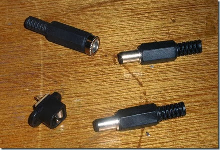
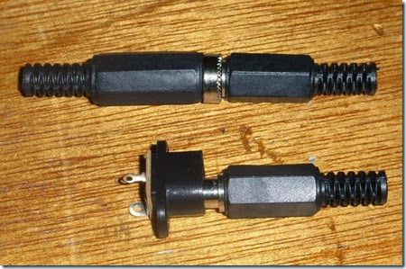
Next up in the arsenal, we need the power jacks to pass the power from the AC wall wart to the camera. I checked the camera, and it used a standard 2.1mm power jack. I picked up 2 example jacks from an electronics supplier.

clip_image005

The top set is an inline jack and plug, which costs $1.20 for the set. The bottom set is an panel mount jack and plug, which costs considerably less, at only 50¢ for the set. First, check to make sure they work together.

clip_image006

I soldered 2 wires to the power plug that were equal length to the ethernet dongle I already had on hand. I slipped some shrink tubing over it, then made the connections.

With the Power Connections, polarity doesn’t matter as much as making sure you don’t flip the circuit with your cable build. If you decide blue is tip and brown is ground, stick with it at both ends of the injectors – not following this is a sure way of destroying the device you’re powering.

In my case, I connected the tip of the power plug to BOTH the 2 blue wires, and the shield to BOTH the 2 brown wires. On the other side, I connected the same to the tiny panel-mount power jack. I then used hot-melt glue to mount the panel mount to the remaining plastic frame.

Why connect to both wires? In case one wire fails in a regular ethernet cable, it’ll still work. Plus, there is less voltage loss with the larger combined wire. The total voltage loss is negligible for most installs. If you find your device isn’t working properly, check to see if the cable is too long, and the voltage is too low to power the device.

Next up the complex ethernet wiring….

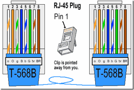
Common straight-through ethernet cables only use 4 wires out of the 8 inside the sheathing. The common wiring in illustrated below.

clip_image007

Take your short working ethernet cord and cut it in half. You’ll want 2 short 8″ pieces, with the working ethernet RJ-45 ends still attached. Strip off an inch at the cut end, and expose the 8 wires inside. Cut the blue and brown sets of wires off. These are unused in this application – these ‘dongles’ will be the ethernet in and out connections.

image

So the ethernet wires (in most cases, you should check) that we’ll be using to pass the ethernet traffic is the 2 orange wires and the 2 green wires, which fall on pins 1, 2, 3 and 6. Simply connect the pin 1 on the ethernet dongle to pin 1 on the ethernet connector jack, and so on through the other 7 wires on both sides.

Finished Power Over Ethernet Injector and Splitter

image

I covered open connections with shrink tubing, then tucked all wires inside the tiny connector cases. I then used hot-melt glue to seal up the open ends of the connectors, and now I have a matched pair of Power Over Ethernet Injectors!

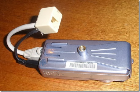
Installed at the Camera End

clip_image025

Simply attach one end of your 100+ foot long ethernet cable to this end, place your camera anywhere, with only one cable feeding to it.

Installed at Hub/Switch End

clip_image026

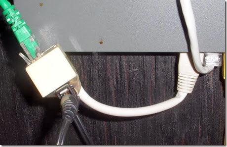
At the other end, at the switch/hub (also suitably close to a power outlet), simply plug it into an available port, plug in the power supply, then the camera feed line.

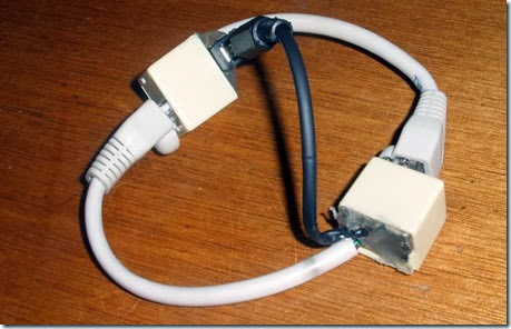
Shield your eyes! Cable Porn! Shocking double-69 cable-on-cable action!

clip_image027

Based On: http://underdesign.wordpress.com/2010/04/07/make-your-own-power-over-ethernet-injector/

PoE Standart Details: http://www.ieee.li/pdf/viewgraphs/introduction_to_poe_ieee802.3af_802.3at.pdf

Monday, November 4, 2013

Linux Swap Space – All You Need to Know

All about Linux swap space

By Gary Sims

Linux divides its physical RAM (random access memory) into chucks of memory called pages. Swapping is the process whereby a page of memory is copied to the preconfigured space on the hard disk, called swap space, to free up that page of memory. The combined sizes of the physical memory and the swap space is the amount of virtual memory available.

Swapping is necessary for two important reasons. First, when the system requires more memory than is physically available, the kernel swaps out less used pages and gives memory to the current application (process) that needs the memory immediately. Second, a significant number of the pages used by an application during its startup phase may only be used for initialization and then never used again. The system can swap out those pages and free the memory for other applications or even for the disk cache.

However, swapping does have a downside. Compared to memory, disks are very slow. Memory speeds can be measured in nanoseconds, while disks are measured in milliseconds, so accessing the disk can be tens of thousands times slower than accessing physical memory. The more swapping that occurs, the slower your system will be. Sometimes excessive swapping or thrashing occurs where a page is swapped out and then very soon swapped in and then swapped out again and so on. In such situations the system is struggling to find free memory and keep applications running at the same time. In this case only adding more RAM will help.

Linux has two forms of swap space: the swap partition and the swap file. The swap partition is an independent section of the hard disk used solely for swapping; no other files can reside there. The swap file is a special file in the filesystem that resides amongst your system and data files.

To see what swap space you have, use the command swapon -s. The output will look something like this:

Filename Type Size Used Priority

/dev/sda5 partition 859436 0 -1

Each line lists a separate swap space being used by the system. Here, the 'Type' field indicates that this swap space is a partition rather than a file, and from 'Filename' we see that it is on the disk sda5. The 'Size' is listed in kilobytes, and the 'Used' field tells us how many kilobytes of swap space has been used (in this case none). 'Priority' tells Linux which swap space to use first. One great thing about the Linux swapping subsystem is that if you mount two (or more) swap spaces (preferably on two different devices) with the same priority, Linux will interleave its swapping activity between them, which can greatly increase swapping performance.

To add an extra swap partition to your system, you first need to prepare it. Step one is to ensure that the partition is marked as a swap partition and step two is to make the swap filesystem. To check that the partition is marked for swap, run as root:

fdisk -l /dev/hdb

Replace /dev/hdb with the device of the hard disk on your system with the swap partition on it. You should see output that looks like this:

Device Boot Start End Blocks Id System

/dev/hdb1 2328 2434 859446 82 Linux swap / Solaris

If the partition isn't marked as swap you will need to alter it by running fdisk and using the 't' menu option. Be careful when working with partitions -- you don't want to delete important partitions by mistake or change the id of your system partition to swap by mistake. All data on a swap partition will be lost, so double-check every change you make. Also note that Solaris uses the same ID as Linux swap space for its partitions, so be careful not to kill your Solaris partitions by mistake.

Once a partition is marked as swap, you need to prepare it using the mkswap (make swap) command as root:

mkswap /dev/hdb1

If you see no errors, your swap space is ready to use. To activate it immediately, type:

swapon /dev/hdb1

You can verify that it is being used by running swapon -s. To mount the swap space automatically at boot time, you must add an entry to the /etc/fstab file, which contains a list of filesystems and swap spaces that need to be mounted at boot up. The format of each line is:

Since swap space is a special type of filesystem, many of these parameters aren't applicable. For swap space, add:

/dev/hdb1 none swap sw 0 0

where /dev/hdb1 is the swap partition. It doesn't have a specific mount point, hence none. It is of type swapwith options of sw, and the last two parameters aren't used so they are entered as 0.

To check that your swap space is being automatically mounted without having to reboot, you can run the swapoff -a command (which turns off all swap spaces) and then swapon -a (which mounts all swap spaces listed in the /etc/fstab file) and then check it with swapon -s.

Swap file

As well as the swap partition, Linux also supports a swap file that you can create, prepare, and mount in a fashion similar to that of a swap partition. The advantage of swap files is that you don't need to find an empty partition or repartition a disk to add additional swap space.

To create a swap file, use the dd command to create an empty file. To create a 1GB file, type:

dd if=/dev/zero of=/swapfile bs=1024 count=1048576

/swapfile is the name of the swap file, and the count of 1048576 is the size in kilobytes (i.e. 1GB).

Prepare the swap file using mkswap just as you would a partition, but this time use the name of the swap file:

mkswap /swapfile

And similarly, mount it using the swapon command: swapon /swapfile.

The /etc/fstab entry for a swap file would look like this:

/swapfile none swap sw 0 0

How big should my swap space be?

It is possible to run a Linux system without a swap space, and the system will run well if you have a large amount of memory -- but if you run out of physical memory then the system will crash, as it has nothing else it can do, so it is advisable to have a swap space, especially since disk space is relatively cheap.

The key question is how much? Older versions of Unix-type operating systems (such as Sun OS and Ultrix) demanded a swap space of two to three times that of physical memory. Modern implementations (such as Linux) don't require that much, but they can use it if you configure it. A rule of thumb is as follows: 1) for a desktop system, use a swap space of double system memory, as it will allow you to run a large number of applications (many of which may will be idle and easily swapped), making more RAM available for the active applications; 2) for a server, have a smaller amount of swap available (say half of physical memory) so that you have some flexibility for swapping when needed, but monitor the amount of swap space used and upgrade your RAM if necessary; 3) for older desktop machines (with say only 128MB), use as much swap space as you can spare, even up to 1GB.

The Linux 2.6 kernel added a new kernel parameter called swappiness to let administrators tweak the way Linux swaps. It is a number from 0 to 100. In essence, higher values lead to more pages being swapped, and lower values lead to more applications being kept in memory, even if they are idle. Kernel maintainer Andrew Morton has said that he runs his desktop machines with a swappiness of 100, stating that "My point is that decreasing the tendency of the kernel to swap stuff out is wrong. You really don't want hundreds of megabytes of BloatyApp's untouched memory floating about in the machine. Get it out on the disk, use the memory for something useful."

One downside to Morton's idea is that if memory is swapped out too quickly then application response time drops, because when the application's window is clicked the system has to swap the application back into memory, which will make it feel slow.

The default value for swappiness is 60. You can alter it temporarily (until you next reboot) by typing as root:

echo 50 > /proc/sys/vm/swappiness

If you want to alter it permanently then you need to change the vm.swappiness parameter in the /etc/sysctl.conf file.

Conclusion

Managing swap space is an essential aspect of system administration. With good planning and proper use swapping can provide many benefits. Don't be afraid to experiment, and always monitor your system to ensure you are getting the results you need.

Taken From: http://www.linux.com/news/software/applications/8208-all-about-linux-swap-space

Thursday, October 31, 2013

How to Create a Windows 8 Portable (USB Stick)

 How to Create a Portable Version of Windows 8 Without Extra Software

clip_image002

For a long time Linux users have been able to install their OS onto a portable USB drive, but Windows just caught up. Read on to find out how you can install Windows 8 onto a USB drive so you can take it wherever you go.

Note: This was written on the RTM version of Windows 8 Enterprise and you will need to have an RTM build of the Enterprise edition to complete the steps in this article.

Using Windows To Go to Create a Portable Workspace

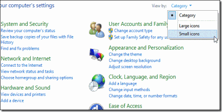
Press the Win + X keyboard combination and select Control Panel from the context menu.

clip_image004

You will need to change your Control Panel view to the Small Icons view.

clip_image006

You should now see Windows To Go near the bottom of the Control Panel, click on it.

clip_image008

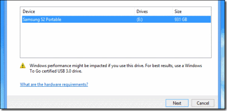
You will now need to select the USB drive you would like to turn into a portable workspace, then click next.

clip_image010

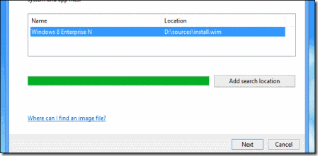
The wizard will automatically scan your CD\DVD and Removable drives for valid Windows installation files, once you have selected a version of Windows click next.

Note: If you store your installation files elsewhere you will need to add it as a search location.

clip_image012

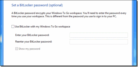
You can optionally set a BitLocker password, but we’ll pass on this option for now.

clip_image014

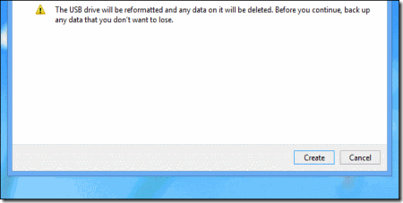
Once you have reached the end of the wizard, you will be warned that your USB drive will be formatted. You can then click on create to kick of the creation process.

clip_image016

That’s all there is to it, you now have a bootable USB with Windows on it.

clip_image018

Note: Your portable USB will not show up in Explorer, this leaves us with a problem later on when you don’t need to use it as a Portable Workspace anymore.

How To Reformat Your Windows To Go USB Drive

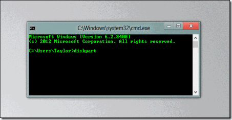
If you’re done using Windows on a drive, you can reformat the drive, but you’ll need to open a command prompt and type diskpart, then press enter.

clip_image020

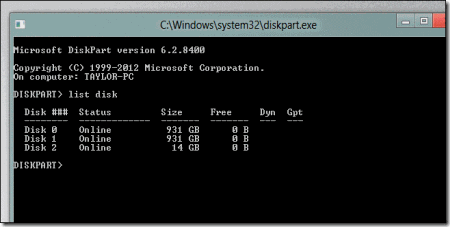
Once you enter Diskpart you will need to find out which drive is the one you need to format, the list disk command will show you all the drive currently connected to your system. Take note of your drive number because we will need it in the next step.

clip_image022

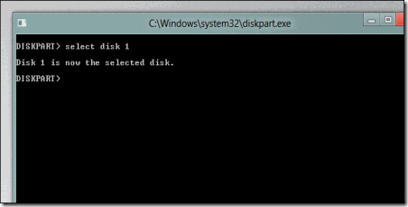
We now need to select the disk, you can simply use the select disk command along with your drive number from the previous step.

clip_image024

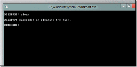
Now that the disk is selected we can go ahead and wipe it.

Note: Clean is a ruthless command that will wipe all the file systems off your drive without any warnings, if you have selected the wrong drive previously this will result is a loss of data so make sure you have the right drive selected.

clip_image026

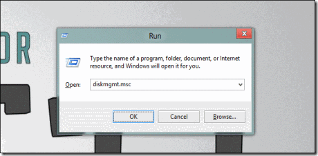
We can now use the Win + R keyboard combination to bring up the run box  and open Disk Management.

clip_image028

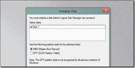
As soon as the Management console opens you will need to initialize the disk.

clip_image030

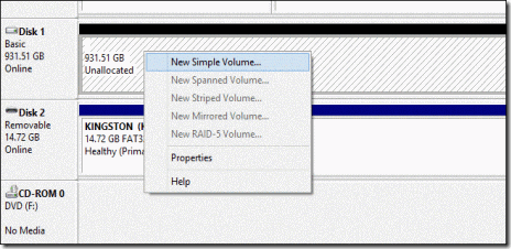
Then you can go ahead and create your drives partition.

clip_image032

That’s all there is to it.

Taken From: http://www.howtogeek.com/121322/how-to-create-a-portable-version-of-windows-8-without-extra-software/

How To Install JAVA on Debian (via Repository)

HOW TO INSTALL ORACLE JAVA 7 IN DEBIAN VIA REPOSITORY

A quick tip for Debian users who want to install and stay up to date with the latest Oracle Java 7 (JDK7): the WebUpd8 Java 7 PPA works on Debian too since the package is just an installer and all you have to do is manually add the PPA repository to the Software Sources.

As a reminder, the Oracle Java 7 PPA repository does not host any Java files but only an installer that automatically downloads and installs Oracle Java 7, like the flashplugin-installer package for instance.

To add the WebUpd8 Oracle Java PPA repository to the Software Sources in Debian (tested on Debian Squeeze, but it should work with any Debian version), use the following commands:

su -

echo "deb http://ppa.launchpad.net/webupd8team/java/ubuntu precise main" | tee -a /etc/apt/sources.list

echo "deb-src http://ppa.launchpad.net/webupd8team/java/ubuntu precise main" | tee -a /etc/apt/sources.list

apt-key adv --keyserver keyserver.ubuntu.com --recv-keys EEA14886

apt-get update

apt-get install oracle-java7-installer

exit

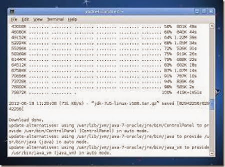
clip_image002

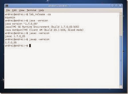
clip_image004

And that's it, Oracle Java 7 (both JDK7 and JRE7) should now be installed and you should receive automatic updates with future Oracle Java 7 versions, under Debian.
Update: the current JDK version in the PPA is Oracle Java 7 Update 10 (7u10).

Setting Java environment variables

To automatically set up the Java 7 environment variables, you can install the following package:

sudo apt-get install oracle-java7-set-default

If you've already installed oracle-java6-set-default or oracle-java8-set-default, they will be automatically removed when installing oracle-java7-set-default (and the environment variables will be set for Oracle Java 7 instead).
For installing Oracle Java 7 in Ubuntu, see: Install Oracle Java 7 in Ubuntu via PPA Repository

Taken From: http://www.webupd8.org/2012/06/how-to-install-oracle-java-7-in-debian.html

Friday, October 18, 2013

Raspberry PI – BerryBoot Bootloader (Multi OS + USB)

BerryBoot v2.0 – bootloader

Universal Operating System Installer

clip_image002[4]

For people short on SD cards: Berryboot is a simple boot selection screen, allowing you to put multiple Linux distribution on a single SD card.

In addition it allows you to put the operating system files on an external USB hard drive instead of on the SD card itself.

Download link Berryboot for the Raspberry Pi: berryboot-20130908.zip

To install: extract the contents of the .zip file to a normal (FAT formatted) SD card, and put it in your Raspberry Pi. This can be simply done under Windows without any special image writer software.

Once you start your Pi it will start an installer that reformats the SD card and downloads the operating systems files from the Internet.

Other devices

In addition to running on the Raspberry Pi, Berryboot also supports Android tablets, TV sticks and boards that have an Allwinner A10 processor.
For more information see the BerryBoot A10 page

Changelog

→ Moved to: Berryboot Changelog

Walkthrough

clip_image004[4]

If your Pi is connected to the Internet BerryBoot will try to detect your location based on your IP-address, and set the right timezone automatically. Verify that it is correct and press “ok”

clip_image006[4]

Select where you want to store the operating system files, and press “format” You can install the operating system files on the SD card itself or an external USB stick/disk. Be aware that if you choose an external drive, the files of the operating system will be stored there, but you still need to keep the SD card in the Pi to boot from.

WARNING: all existing files on the disk will be erased.

clip_image008[4]

Select which operating system you want to install. You can add more later.

clip_image010[4]

It will download the files from the Internet automatically.

clip_image012[4]

In the Berryboot menu editor you can install more operating systems, rename them, delete them, etc. Press “exit” to exit the editor and start using the operating system you installed.

HDMI CEC support

When attached to a HDMI TV, you can also use the arrows on your TV remote to select an operating system to boot, instead of using your keyboard or mouse.

Available options in menu editor

§ “Add OS” (or CTRL+A on keyboard, red button on TV remote)
Single click to download additional operating systems from the Internet.
Hold down your mouse button over the “Add OS” button and select “copy OS from USB stick”, to install an operating system saved on USB stick.

§ “Edit” (or ENTER on keyboard)
Change the name of the selected operating system.
You used to be able to change the memory split setting here as well, but for new installations (that have CMA enabled) this is no longer used.

§ “Clone”
Creates a copy of the selected operating system.
It is possible to create either a copy that includes the file system changes you made, or create a copy of the original operating system image as downloaded from the Internet.

§ “Backup”
Creates a backup of a single operating system or all of them to a USB stick, or SD card (requires USB SD card reader).
Backups of individual images can be restored by holding down the “add OS” button and selecting “copy OS from USB stick”

§ “Delete” (or DEL on keyboard)
Deletes the files of the selected operating system.

§ “Make default”
Makes the selected operating system the default. On boot, this operating system will be started automatically unless another is selected within a number of seconds.

§ “Exit” (or ESC on keyboard)
Exits the menu editor.

Advanced options

clip_image014[4]

Click on the ”»” button to the right of the screen to see all options.

§ “Advanced configuration”
Editor for configuration files such as cmdline.txt and config.txt

When using a Raspberry Pi you can specify kernel parameters and Berryboot parameters in cmdline.txt (use uEnv.txt if you have another device).
Special Berryboot parameters:

bootmenutimeout=<number of seconds> - number of seconds before default operating system is started. nobootmenutimeout - do not start the default operating system automatically.

In config.txt advanced overscan, HDMI and overclocking settings can be specified. See the RPIconfig page on eLinux.org for details.
Note that overclocking is known to cause SD card filesystem corruption, so only use that when you are using an USB stick or drive as storage and know what you are doing.

§ “Console”
Activates a console on tty2
Press CTRL+ALT+F2 to access, username “root”, no password.

§ “Set password”
Password protects access to the menu editor, so that unauthorized users cannot delete or edit the operating systems.

§ “Repair filesystem”
Performs a file system check and repair. Attempts to repair file system corruption. Can perform a lot of writes to the SD card, so you might want to make a backup of important files first.

Alternative installation method using disk image

If you are experiencing problems unpacking the installation files to a FAT formatted SD card (the easiest and recommend installation method), you can alternatively use a tool like Win32diskimager or dd to write this disk image to the card.
The disk image is meant to install Berryboot on another device, but it includes the Raspberry Pi boot files as well.

More information

For advanced users:

§ Headless installation (install Berryboot without display attached, using VNC)

§ Adding your own custom operating systems to the menu

§ Berryboot source code on Github

§ Report bugs

Taken From: http://www.berryterminal.com/doku.php/berryboot

Raspberry Pi – Low Cost HD CCTV Camera

Raspberry Pi as Low-Cost HD Surveillance Camera

By Christoph Buenger, DaSpors, 11 Oct 2013

Introduction

This article describes how to build a surveillance cam based on a Raspberry Pi micro-computer which records HD video when something moves in the monitored area. Live picture can be viewed from any web browser, even from your mobile while you're on the road.

What you will get:

· See live stream in any web browser from anywhere

· Record any motion into video file 

Usually, such a cam will cost you around US$2.000, but with the result from this article, you will get such a cam for only about US$100.

Background

Have you ever heard of Raspberry Pi? It's a low-cost micro-computer that is able to run Linux and has endless extension possibilities. It cost only about US$35 and opens up endless possibilities of what you can build with it. The official website can be found at http://www.raspberrypi.org/

Hardware components 

We need some hardware for this project. This is a list of the major things we need: 

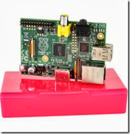
· Raspberry Pi Model B:  This is the larger model of the Raspberry computer system with 700MHz and 512MB Ram. It supports HD video. Start here to see where you can order it in your country: http://www.rs-components.com/raspberrypi. Cost: about US$35 clip_image001
· Raspberry Pi Camera Module: This module was specially build for the Raspberry micro-computer. It has a connector to be plugged directly into the Raspberry board and supports HD video up to 1080p. The website http://www.rs-components.com/raspberrypi will show you where you could order it from your country. I.e. http://www.alliedelec.com/lp/130513rasocameramodule/ ships this camera in the US for only US$29
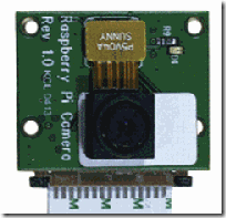
clip_image003

·  A housing for the camera:  you don't need to buy a high-price-housing for your Raspberry. There are loads of very cheap fake security cameras available which perfectly fit our needs here. Search the web for "surveillance camera dummy" and you will find loads of housings for your new camera for only a few dollars. I.e. this one will do the job: http://amzn.to/15XLaAj for only US$9. We have ordered this camera housing for about 20€ in Germany that had enough space for all the components: http://amzn.to/19CTEaN. You can use any camera housing, but only be careful about the size of the housing so that the Rasperry board will fit in there. The dimensions of the Raspberry board are 85.6 x 53.98 x 17 mm (approx 3.37 x 2.13 x 0.67 in). 
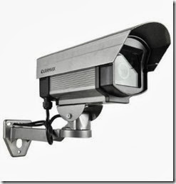
clip_image004

· Power supply: The Raspberry computer does not come with any power supply, you have to get one on our own. Any power supply with a micro-USB plug can do the job as long as it supplies 1A of power. We have ordered such a power supply plus a USB-to-micro-USB cable for about US$15: http://www.alliedelec.com/Search/ProductDetail.aspx?SKU=70232557
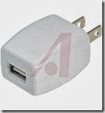
clip_image005

· SD card: as the Raspberry Pi does not have any storage on board, you need to add some so that you can install and run the operating system for this device. Any SD or microSDHC should do the job, but we recommend using a Class 10 SD card. It's only around US$7
clip_image006

· To connect this cam to your network, you also need some kind of network connection. One possibility is to use a LAN connection, but you would need to put LAN cable to the point where you want to mount the camera. A better alternative is such a wifi USB adapter for only about US$10:
clip_image007

That's all: for about US$105 we have all the hardware we need to build this HD surveillance cam. 

Install Raspbian 

At first, you should install the OS and software to the Raspberry Pi before mounting it all together. An OS is the basic operating system software that tells the Raspberry hardware what to do. Linux is perfect for this. We have chosen Raspbian, as it's one of the most advanced OS for the Raspberry with loads of help and tutorials on the internet.

You need to prepare the SD card to be able to run Raspbian on the Raspberry: this excellent tutorial from Adafruit will explain the necessary steps.

Now temporarily connect your Raspberry Pi board to LAN cable, a monitor (HDMI TV works out of the box, but a HDMI-to-DVI cable like this will do the job as well) and a USB keyboard for the basic setup.

Insert the prepared SD card with the Raspbian installer on it and attach the power supply.

The Raspberry should boot up and guide you through the setup process as explained in this Adafruit tutorial. After this, you should have a basic Raspbian OS running.

Be sure to enable SSH in Raspbian so that you are able to control the Raspberry device also when there is no monitor and keyboard attached. 

Connect via SSH 

Now that the basic setup is done, you should connect to your Raspberry device from your computer. You can connect to Linux console from any computer in your local network and control it like you where sitting directly in front of it. This is very important as once mounted far away from your desktop, you need to be able to make updates and change the configuration of this camera any time later without the need to detaching it from the wall and bringing it back to your desk.

Remember that this cam is not just a dump cam device but a very powerful computer with Linux OS running on it. It's not limited to what we explain in this article now; it will follow any development in software so that you will be able to install updated software and more modules any time later.

First, you need a software to connect to the Linux console on the Raspberry. For Windows, you will need the extra (free) software PuTTY. Download it from the PuTTY website, install it and connect to your Raspberry Pi device:
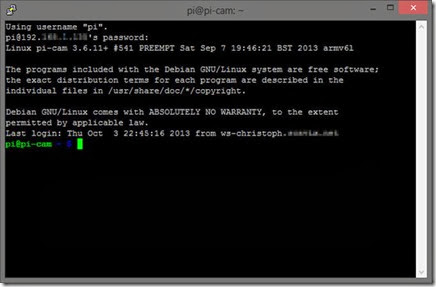
clip_image008

From now on, you don't need any monitor and keyboard attached to the Raspberry anymore. 

Enable wifi 

If you want to run this camera with a wifi USB dongle (like we've suggested above), you will need to do some quick additional steps to make wifi work on the Raspberry: 

From the console (PuTTY window), edit the network properties of the Raspberry:

sudo nano /etc/network/interfaces

Now add these lines at the end of the file (or change existing lines to match these):

allow-hotplug wlan0

iface wlan0 inet dhcp

wpa-ssid "YOUR NETWORK SSID"

wpa-psk "WIFI PASSWORD"

(Fill in the SSID and password for your wifi network)

Reboot the Raspberry with this command and see if it correctly connects to your wifi network:

sudo reboot

Put the hardware together 

Now it's time to assemble all the hardware components together into the housing. Depending on the housing, this should not be a too complicated job:
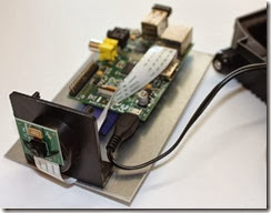
clip_image010

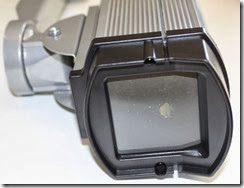
As our housing had a very large glass window at the front, we have closed it with a black paper with a hole in it:
clip_image011

This also has the advantage that the red recording light of the Raspberry Pi camera module is not visible anymore. If you like the camera recording led to be visible, don't cover it. Whenever the camera is detecting any motion or is recording, the led light will glow in a very bright red.  

Installing the motion detection software 

A very good (and free) motion detection/surveillance software with many configuration options is motion. As the current version of this software does not support the Raspberry camera module yet, we've followed this special instructions to download and install a special build with support for this camera module. We're pretty sure that the official build of motion will shortly also support the Raspberry camera module as well.

A very important command to edit the motion configuration file is

sudo nano /etc/motion.conf

We've made some changes to the motion.conf file to fit our needs. Our current motion.conf file can be downloaded here: raspberry_surveillance_cam_scavix.zip

Some of the main changes are:

Make sure that motion is always running as a daemon in the background:

daemon on

As we want to use a high quality surveillance video, we've set the resolution to 1280x720:

width 1280

height 720

We don't need real-time video, 2 pictures per second are totally ok for our needs:

framerate 2

This is a very handy feature of the motion software: record some (2 in our configuration) frames before and after the motion in the image was detected:

pre_capture 2

post_capture 2

We don't want endless movies. Instead, we want to have max. 10 minutes slices of the motion videos:

max_movie_time 600

Enable access to the live stream from anywhere. Otherwise only localhost (= the Raspberry device) would be allowed to access the live stream:

stream_localhost off

If you want to protect the live stream with a username and password, you should enable this:

stream_auth_method 2

stream_authentication SOMEUSERNAME:SOMEPASSWORD

All configuration parameters are explained in detail in the motion config documentation.

Save videos on Windows shared folder

As the SD card of the Raspberry Pi is a pretty limited resource, we've decided to let the Raspberry cam store the videos on one of our Windows Servers. This is pretty easy:

First share a folder from some Windows machine. Just follow some guides on the internet if you've never shared a folder from a Windows machine before.

Then open the fstab configuration on your Raspberry from a PuTTY console or directly from the device:

sudo nano /etc/fstab

Now add an extra line with the configuration of your Windows network shared folder: 

//YOURSERVERNAME/YOURSHAREDFOLDERNAME /mnt/camshare cifs username=YOURSHAREDFOLDERUSERNAME,password=YOURSHAREDFOLDERPASSWORD,iocharset=utf8,file_mode=0777,dir_mode=0777 0 0

After a reboot, the Raspberry should have an extra folder /mnt/camshare mounted to the Windows shared folder. You should now set in your motion.conf

target_dir /mnt/camshare

so that motion saves all movies to the shared folder on the Windows machine.

Fix motion autostart 

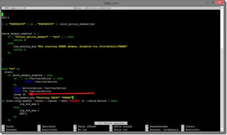
We had some trouble that motion was not automatically started on a reboot of the Raspberry. We've found out that this was because the mounted folder of the Windows machine was not yet ready when motion tried to access it.

A very quick fix solved our problem:

Just edit the motion file with

sudo nano /etc/init.d/motion

and add the line

sleep 30

to the start-sequence:
clip_image012

Our changed /etc/init.d/motion script can be found in the attached raspberry_surveillance_cam_scavix.zip

Mounting the camera 

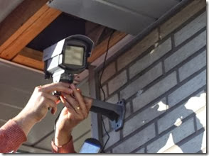
After all these steps, you can finally mount the surveillance camera to the destination point.
clip_image013

Some helpful hints: 

· Be sure to place the power supply in a dry and safe place

· Keep an eye on the wifi signal: if you mount the camera out of range of the wifi, it won't be able to send any video and motion videos  

Accessing the live stream

Now you can access the live stream from the camera from any browser via the url http://IPADDRESSOFRASPBERRY:8080 

Where 8080 is the port that we've configured for our stream in the motion.conf file. See your own configuration setting "stream_port" in motion.conf for the port.

We've found out that Google Chrome 30 (not even on iOS) was not able to play this stream directly due to a bug in the underlying Chromium project. But any other browser like Internet Explorer, FireFox, Safari and even VLC media player was able to show the live stream of the camera.
A workaround for this is to create a simple html file that contains one large image with the stream-url of the camera. See the file cam.html from raspberry_surveillance_cam_scavix.zip. This way, Chrome can show the live stream as well. Let's hope that Chrome will fix this issue in their browser. 

Access live stream from anywhere 

To make the live stream accessible from anywhere, you will need to enable some kind of dynamic domain services to your local network. This will enable you to always be able to connect to your local IP address from the outside even if your local IP address changes (over here in Germany, every private DSL ip address changes every 24 hours). 

Such a (free) service enables you to access your Raspberry from anywhere even if your ip address changes. A very good service we're using for some years now is dyn.com. They have some free services and are integrated in many routers. 

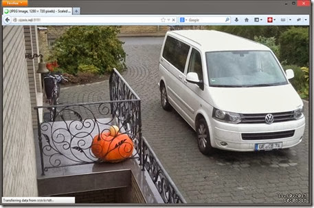
Once you have set up the dynamic ip url, you can access the camera stream from anywhere in your browser (i.e. http://YOURDYNAMICDOMAIN:8080):
clip_image014

And this also works from the browser on your mobile device:

clip_image015

Advanced steps 

There are a thousand things you can do with such a surveillance cam basic setup now. How about sending Growl notifications when some motion was detected? This guide explains how to add this functionality easily. 

Or you could easily add a temperature-sensor to the cam. It's only a few bucks and can be integrated very easily

We're currently working on integrating the live stream into MediaPortal server so that we can switch to a TV channel to see the live stream from the cam in our office.

If you want extra security, you could also add a battery pack to the camera. Be sure to buy one that is able to charge simultaneously while powering the Raspberry. This would enable you to detect if some bad guy cuts the power strips of your camera and send some alert messages to you (i.e. SMS or email) including the video of the disturber.

What are you going to add? Let us know!

History 

10/10/2013: Initial release of article

License

This article, along with any associated source code and files, is licensed under The Code Project Open License (CPOL)

About the Authors

Christoph Buenger

CEO Scavix Software Ltd. & Co. KG
Germany clip_image017

Scavix Software offers high quality software development and consulting. That's what customers like Intel, AMD, eBay and Sage Software trusted in the last 6 years. Be it on the desktop, in the web browser, on a mobile phone, on a tablet or on the TV: we can make your software visions come true.
Are you our next customer? Don't hesitate to contact us.

Taken From: http://www.codeproject.com/Articles/665518/Raspberry-Pi-as-low-cost-HD-surveillance-camera