Friday, April 25, 2014

Connect Arduino To Your TV

TV Out with Arduino

clip_image001

This Instructable is for those who would like to use your Arduino to output to a TV. Granted the Arduino is only powerful enough to produce a black and white picture it can still be fun to play with and useful for some projects.

Step 1: Item list

clip_image003

clip_image004

Things you will need:

Hardware

  • Arduino
  • A TV
  • A Protoboard or PCB
  • 2 Resistors
      • 1x 470 ohm ( Yellow, Violet, Brown )
      • 1x 1k ohm ( Brown, Black, Red )
  • 2x 2-Pin headers (Only 3 are used but the 4th helps with stability)
  • Spare RCA cord you don't mind cutting up

Software
- Arduino Software ( http://arduino.cc/en/Main/Software )
- The TVout library ( http://code.google.com/p/arduino-tvout/ )

Step 2: Assembly

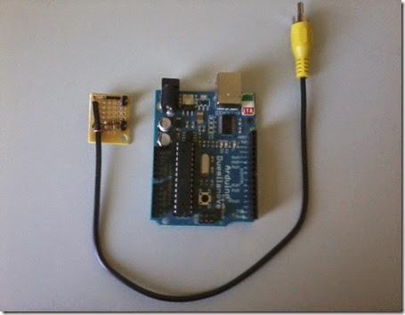
clip_image005

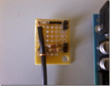
clip_image006

Ok I had already made this connector piece before I decided to make an Instructable.. And I apologize for the poor quality of the images, my cell phone's camera isn't the best but I think you'll get the point.

I got this schematic from the TVout Libraries Google code website:http://code.google.com/p/arduino-tvout/

Step 3: Programming

clip_image007

Now for the fun part... Programming...

When it comes to the TVout Library there is a new version but it's still in beta and I've found it to be buggy so I just use the R5.91 release (http://code.google.com/p/arduino-tvout/downloads/detail?name=TVout_R5.91.zip&can=2&q=)

I'm assuming you have a basic knowledge of Arduino programming so I won't go into too much detail here..

For a complete list of commands for the TVout Library go here( http://code.google.com/p/arduino-tvout/wiki/FDcomplete )

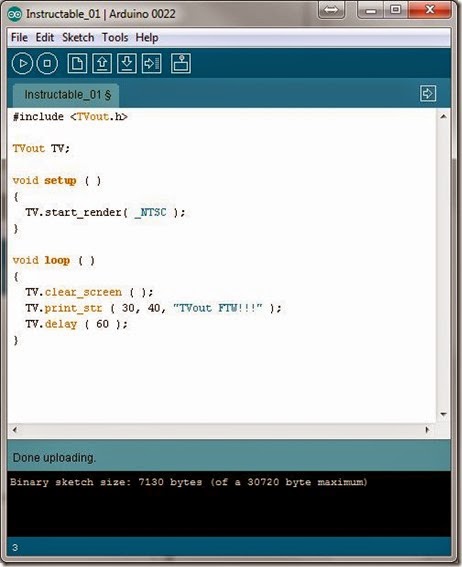
Instructable_01.pde

#include <TVout.h>
TVout TV;
unsigned char x, y;

void setup ( )
{
    TV.start_render( _NTSC );
}

void loop ( )
{
    TV.clear_screen ( );
    TV.print_str ( 10, 10, "TVout FTW!!!" );
    TV.delay ( 60 );
}

For PAL (Europe) TVs just replace the:

  TV.start_render( _NTSC );

with:

  TV.start_render( _PAL );

Step 4: Finished Product

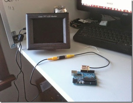
clip_image001[1]

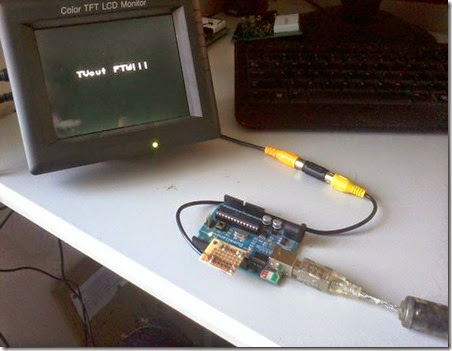
Now this is just the start... There is so many possibilities with this.

Some sites shows how the Arduino can be used as a game console:

Wayne and Layn LLC now makes a shield that uses this library, the video game shield

Nootropic design is selling a stand alone arduino compatible board the

Also I (JuggaloMemnoch) plan on releasing more projects to further explore uses of the Arduino and TVout library

Base On: http://www.instructables.com/id/TV-Out-with-Arduino/

Sunday, April 20, 2014

Mount Windows Network Shares on Linux

Linux mount CIFS Windows Share

clip_image001

Q. How do I mount CIFS (Windows Network Shares) Windows Server / XP / Vista Shared folder under Linux operating systems?

A. Common Internet File System is an application-level network protocol mainly used to provide shared access to files, printers, serial ports, and miscellaneous communications between nodes on a network. You can easily access CIFS (Windows Share) share from Linux and mount them as a regular filesystem.

Mount Linux CIFS share

Mount CIFS (Windows Share) with the default local filesystem permissions:

# mkdir /mnt/cifs
# mount -t cifs //server-name/share-name /mnt/cifs -o username=shareuser,password=sharepassword,domain=nixcraft

# mount -t cifs //192.168.101.100/sales /mnt/cifs -o username=shareuser,password=sharepassword,domain=nixcraft


OR
# mount.cifs //192.168.101.100/sales /mnt/cifs -o username=shareuser,password=sharepassword,domain=nixcraft

Where,

  • username=shareuser : specifies the CIFS user name.
  • password=sharepassword : specifies the CIFS password. If this option is not given then the environment variable PASSWD is used. If the password is not specified directly or indirectly via an argument to mount, mount will prompt for a password, unless the guest option is specified.
  • domain=nixcraft : sets the domain (workgroup) of the user

Taken From: http://www.cyberciti.biz/faq/linux-mount-cifs-windows-share/

Sunday, April 13, 2014

Raspberry Pi - GPIO Pins and Python

Tutorial: Raspberry Pi GPIO Pins and Python

· By Mark Kleback
clip_image002
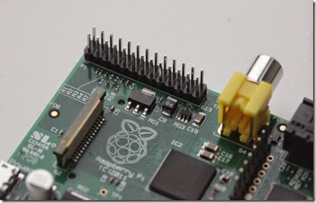
The GPIO pins on a Raspberry Pi are a great way to interface physical devices like buttons and LEDs with the little Linux processor. If you’re a Python developer, there’s a sweet library called RPi.GPIO that handles interfacing with the pins. In just three lines of code, you can get an LED blinking on one of the GPIO pins.

INSTALLATION

The newest version of Raspbian has the RPi.GPIO library pre-installed. You’ll probably need to update your library, so using the command line, run:


sudo python
import RPi.GPIO as GPIO
GPIO.VERSION

The current version of RPi.GPIO is 0.5.4 If you need to update to a newer version, run:


sudo apt-get update
sudo apt-get upgrade

If you don’t have the RPi.GPIO library because you’re using an older version of Raspbian, there are great instructions on the Raspberry Pi Spy website on installing the package from scratch.

USING THE RPI.GPIO LIBRARY

Now that you’ve got the package installed and updated, let’s take a look at some of the functions that come with it. Open the Leafpad text editor and save your sketch as “myInputSketch.py”. From this point forward, we’ll execute this script using the command line:

sudo python myInputSketch.py

All of the following code can be added to this same file. Remember to save before you run the above command. To exit the sketch and make changes, press Ctrl+C.

To add the GPIO library to a Python sketch, you must first import it:

import RPi.GPIO as GPIO

Then we need to declare the type of numbering system we’re going to use for our pins:

#set up GPIO using BCM numbering
GPIO.setmode(GPIO.BCM)
#setup GPIO using Board numbering
GPIO.setmode(GPIO.BOARD)

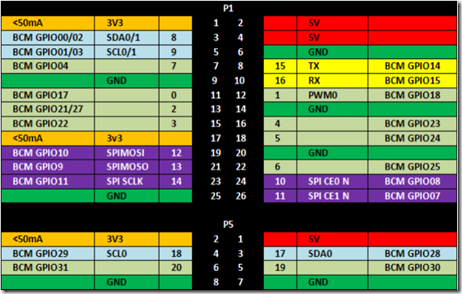
The main difference between these modes is that the BOARD option uses the pins exactly as they are laid out on the Pi. No matter what revision you’re using, these will always be the same. The BCM option uses the Broadcom SoC numbering, which differs between version 1 and version 2 of the Pi.
clip_image003
from Meltwater’s Raspberry Pi Hardware
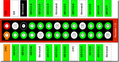
Raspberry-Pi-GPIO-Layout-Revision-1

Raspberry-Pi - GPIO IFs

In the image above, you’ll see that Pin 5 is GPIO01/03. This means that a v.1 Pi is GPIO 01, while a v.2 Pi is GPIO 03. The BCM numbering is what I’ll be using for the rest of this entry, because it’s universal across other programming languages.

BUILDING A CIRCUIT

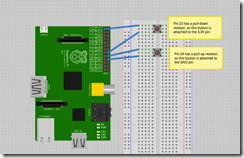
Now we’re going to get into inputs and outputs. In the circuit shown below, two momentary switches are wired to GPIO pins 23 and 24 (pins 16 and 18 on the board). The switch on pin 23 is tied to 3.3V, while the switch on pin 24 is tied to ground. The reason for this is that the Raspberry Pi has internal pull-up and pull-down resistors that can be specified when the pin declarations are made.
clip_image004
To set up these pins, write:

GPIO.setup(23, GPIO.IN, pull_up_down=GPIO.PUD_DOWN)
GPIO.setup(24, GPIO.IN, pull_up_down=GPIO.PUD_UP)

This will enable a pull-down resistor on pin 23, and a pull-up resistor on pin 24. Now, let’s check to see if we can read them. The Pi is looking for a high voltage on Pin 23 and a low voltage on Pin 24. We’ll also need to put these inside of a loop, so that it is constantly checking the pin voltage. The code so far looks like this:

import RPi.GPIO as GPIO
GPIO.setmode(GPIO.BCM)
GPIO.setup(23, GPIO.IN, pull_up_down = GPIO.PUD_DOWN)
GPIO.setup(24, GPIO.IN, pull_up_down = GPIO.PUD_UP)
while True:
if(GPIO.input(23) ==1):
print(“Button 1 pressed”)
if(GPIO.input(24) == 0):
print(“Button 2 pressed”)
GPIO.cleanup()

The indents in Python are important when using loops, so be sure to include them. You also must run your script as “sudo” to access the GPIO pins. The GPIO.cleanup() command at the end is necessary to reset the status of any GPIO pins when you exit the program. If you don’t use this, then the GPIO pins will remain at whatever state they were last set to.

THE PROBLEM WITH POLLING

This code works, but prints a line for each frame that the button is pressed. This is extremely inconvenient if you want to use that button to trigger an action or command only one time. Luckily, the GPIO library has built in a rising-edge and falling-edge function. A rising-edge is defined by the time the pin changes from low to high, but it only detects the change. Similarly, the falling-edge is the moment the pin changes from high to low. Using this definition, let’s change our code slightly:

import RPi.GPIO as GPIO
GPIO.setmode(GPIO.BCM)
GPIO.setup(23, GPIO.IN, pull_up_down = GPIO.PUD_DOWN)
GPIO.setup(24, GPIO.IN, pull_up_down = GPIO.PUD_UP)
while True:
GPIO.wait_for_edge(23, GPIO.RISING)
print(“Button 1 Pressed”)
GPIO.wait_for_edge(23, GPIO.FALLING)
print(“Button 1 Released”)
GPIO.wait_for_edge(24, GPIO.FALLING)
print(“Button 2 Pressed”)
GPIO.wait_for_edge(24, GPIO.RISING)
print(“Button 2 Released”)
GPIO.cleanup()

When you run this code, notice how the statement only runs after the edge detection occurs. This is because Python is waiting for this specific edge to occur before proceeding with the rest of the code. What happens if you try to press button 2 before you let go of button 1? What happens if you try to press button 1 twice without pressing button 2? Because the code is written sequentially, the edges must occur in exactly the order written.

Edge Detection is great if you need to wait for an input before continuing with the rest of the code. However, if you need to trigger a function using an input device, then events and callback functions are the best way to do that.

EVENTS AND CALLBACK FUNCTIONS

Let’s say you’ve got the Raspberry Pi camera module, and you’d like it to snap a photo when you press a button. However, you don’t want your code to poll that button constantly, and you certainly don’t want to wait for an edge because you may have other code running simultaneously.

The best way to execute this code is using a callback function. This is a function that is attached to a specific GPIO pin and run whenever that edge is detected. Let’s try one:

import RPi.GPIO as GPIO
GPIO.setmode(GPIO.BCM)
GPIO.setup(23, GPIO.IN, pull_up_down = GPIO.PUD_DOWN)
GPIO.setup(24, GPIO.IN, pull_up_down = GPIO.PUD_UP)
def printFunction(channel):
print(“Button 1 pressed!”)
print(“Note how the bouncetime affects the button press”)
GPIO.add_event_detect(23, GPIO.RISING, callback=printFunction, bouncetime=300)
while True:
GPIO.wait_for_edge(24, GPIO.FALLING)
print(“Button 2 Pressed”)
GPIO.wait_for_edge(24, GPIO.RISING)
print(“Button 2 Released”)
GPIO.cleanup()

You’ll notice here that button 1 will consistently trigger the printFunction, even while the main loop is waiting for an edge on button 2. This is because the callback function is in a separate thread. Threads are important in programming because they allow things to happen simultaneously without affecting other functions. Pressing button 1 will not affect what happens in our main loop.

Events are also great, because you can remove them from a pin just as easily as you can add them:

GPIO.remove_event_detect(23)

Now you’re free to add a different function to the same pin!

ADDING FUNCTIONALITY

As convenient as callback functions are for the GPIO pins, it still doesn’t change the fact that the Raspberry Pi is just not ideal for analog inputs or PWM outputs. However, because the Pi has Tx and Rx pins (pins 8 and 10, GPIO 14 and 15), it can easily communicate with an Arduino. If I have a project that requires an analog sensor input, or smooth PWM output, simply writing commands to the serial port to the Arduino can make things seamless.

Taken From: http://makezine.com/projects/tutorial-raspberry-pi-gpio-pins-and-python/
Raspberry Pi – Make Your Own Pirate Radio ( PiFM )

Raspberry Pirate Radio

This simple hack turns your Raspberry Pi into a powerful FM transmitter! It has enough range to cover your home, DIY drive-in movie, a high school ball game, or even a bike parade (depending on the stragglers).

PiFM software not only boldly enhances the capability of your Pi, but does so with nothing more than a single length of wire. This hack starts with the absolute minimum you need to run a Raspberry Pi — an SD card, a power source, and the board itself — and adds one piece of wire. It’s the coolest Pi device we’ve ever seen with so few materials.

PiFM was originally created by Oliver Mattos and Oskar Weigl, and revised by Ryan Grassel. We’d like to thank the whole PiFM community for inspiration. MAKE’s contribution to the project, the PirateRadio.py script, now enables playback without using the command line, and handles all the most common music file formats automatically. It was written by MAKE Labs engineering intern Wynter Woods. You can find the source code here.

clip_image001

NOTE: The Raspberry Pi’s broadcast frequency can range between 1Mhz and 250Mhz, which may interfere with government bands. We advise that you limit your transmissions to the standard FM band of 87.5MHz–108.0MHz (see Step 3) and always choose a frequency that’s not already in use, to avoid interference with licensed broadcasters.

Steps

  • 1. Make the antenna.
  • 2. Flash the SD card and add music.
  • 3. Edit the config file.
  • 4. Start it up!
  • 5. How the PiFM software works.
  • 6. Going further.

Step #1: Make the antenna.

clip_image002

· Technically, all you need for an antenna is a piece of wire. For an optimal antenna, you could attach a 75cm wire to pin 4, with a 75cm power cable pointed in the other direction. (That would effectively make a half-wave dipole antenna at 100MHz, near the middle of the FM band.) We just used 40cm of 12 AWG solid wire, since things started tipping over when the wire got longer.

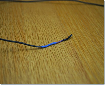
· Cut and strip a female jumper wire. Solder it to one end of your antenna, and insulate with heat-shrink tubing.

· Dab hot glue around the joint for support, and stick it on pin 4 of the GPIO pins of your Raspberry Pi. The glue makes the antenna more rigid so it stands up better.

· NOTE: If you have the Raspberry Pi Starter Kit and you're in a hurry, you can just use a male jumper wire plugged into the Cobbler breakout board! (Both are included in the kit.) It will work, but the range will be roughly half of what you'd get with 40cm of 12 AWG solid copper.

Step #2: Flash the SD card and add music.

clip_image005

· To save you time configuring everything, MAKE Labs made a disk image. Download ithere. (Advanced users who just want the source can find the link in the intro.)

· The original PiFM code proved the concept with impressive results. The MAKE image takes the work out of partitioning the card into system and data partitions. It also auto-mounts the data partition. It uses a fraction of the CPU of the original code and enables playback from MP3, FLAC, and more. And it runs the PirateRadio.py script on startup, so your music starts broadcasting immediately once the transmitter boots up. Ultimately, this will save you a lot of time. But you can't just drag the files to your SD card; it must be flashed to work.

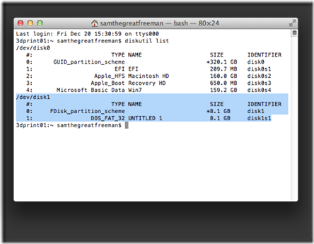
· Flash the image to your SD card. If you're not familiar with the process, it’s easy. Good tutorials can be found here. You can use Win32DiskImager on Windows, or the Command Line Tools (1) instructions if you're on OSX. I'll assume Linux users have moved on already.

· For OSX and Linux users, simply open up the PirateRadio partition and get started. Windows users, follow our instructions for connecting to your Pi via SSH using WinSCP.

· To add music, simply add your artist or album folders to the root of the “Pirate Radio” partition of the SD card. Your music files can be nested within these folders, so there's no need to dump all your music into one mess on the main directory.

Step #3: Edit the config file.

clip_image009

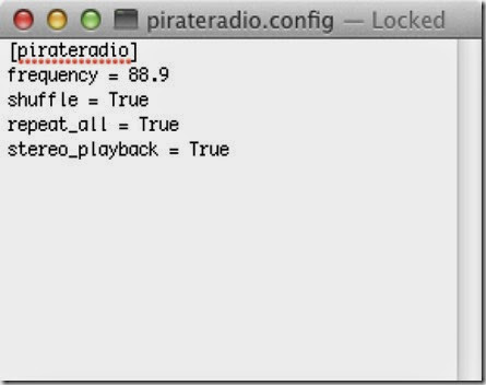
· You can set the frequency you want to broadcast on in the pirateradio.config file. Open it up in a text editor. You should see something like: [pirateradio] frequency = 108.2 shuffle = True repeat_all = True

· Set frequency to the station you want to broadcast on. Useable FM frequencies are typically from 87.5MHz to 108.0MHz. (108.2 was the highest our test radio could reach, and it didn't have any competition from other stations.)

· Set shuffle to True to shuffle files, or to False to play files alphabetically.

· Set repeat_all to True if you want to loop forever through your playlist.

Step #4: Start it up!

clip_image010

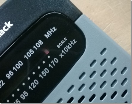
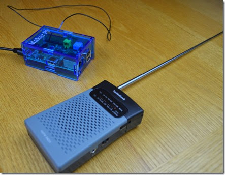
Tune your FM radio (or you Mobile Phone) to your frequency of choice and plug in the Raspberry Pi. It will take about 15 seconds to warm up. Once it does, you should hear your music loud and clear.

Step #5: How the PiFM software works.

clip_image013

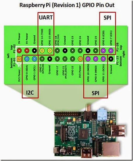
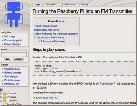
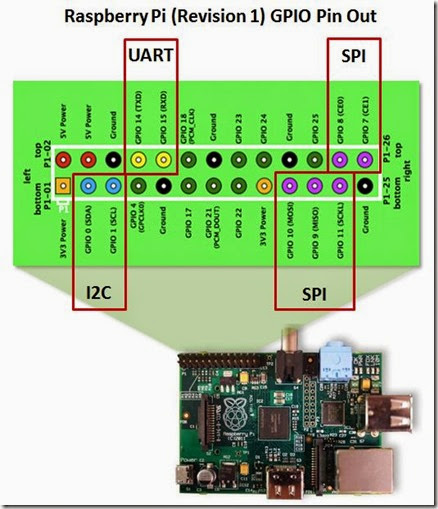
· From the PiFM wiki: "It uses the hardware on the Raspberry Pi that is actually meant to generate spread-spectrum clock signals on the GPIO pins to output FM radio energy. This means that all you need to do to turn the Raspberry Pi into a (ridiculously powerful) FM transmitter is to plug in a wire as the antenna (as little as 20cm will do) into GPIO pin 4 (aka GPCLK0) and run the code."

raspberry-pi-rev-1-gpio-pin-out1

· Frequency modulation "is done by adjusting the frequency using the fractional divider." For example, for a target broadcast frequency of 100MHz, the signal is fluctuated between 100.025Mhz and 99.975Mhz, which makes the audio signal.

· The Python code defaults to 87.9 FM with shuffle and repeat turned off. It scans the SD card for music files and builds a playlist based on the options in the config file. It then passes each file along to a decoder based on the filetype. Each file is then re-encoded into a mono format the PiFM radio can handle. This lets you play more than just WAV files: use your MP3, FLAC, M4A, AAC, or WMA files too.

Step #6: Going further.

clip_image014clip_image016clip_image017

· Tuck everything in the acrylic case that comes with your Raspberry Pi Starter Kit and you're good to go. Or, if you want something cooler or more subversive, try building an awesome housing of your own. MAKE Labs manager Sam Freeman drew up this little number, a cool radio tower; download it at thingiverse.com/makelabs.

· Add RadioShack's handy USB battery pack so you can carry your station wherever you need to take over the airwaves. (It fits inside the radio tower, too.)

· NOTE: If you have trouble with range, double-check which pin your antenna is plugged into. At MAKE Labs we spent a few hours puzzled by our antenna's performance, only to discover it was one pin over!

Publicado em 06/03/2014

Complete instructions for this episode of Weekend Projects can be found at http://makezine.com/projects/raspberr...
Using a readymade disk image and one simple solder connection, turn your Raspberry Pi into a streaming pirate radio.
This project was originally created by Oliver Mattos and Oskar Weigl. It was revised by Ryan Grassel and extended by MAKE Labs engineering intern Wynter Woods. Go team!
NOTE: The Raspberry Pi's broadcast frequency can range between 1Mhz and 250Mhz, which may interfere with government bands. We advise that you limit your transmissions to the standard FM band of 87.5MHz--108.0MHz and always choose a frequency that's not already in use, to avoid interference with licensed broadcasters.

Taken From: http://makezine.com/projects/make-38-cameras-and-av/raspberry-pirate-radio/

How does This Hack Works / Problems

@StavrosKorokithakis Raspberry Pi has clock generators, that can output square wave to the GPIO pins. If you program clock generator to the desired frequency you'll get the signal, and when you change the frequency, the signal becomes a frequency modulated (FM) radio. Bad points of this approach are: 1) square wave is very noisy -- plenty of harmonics and other frequencies are transmitted, 2) RasPi can output a lot of RF power, blocking some other transmissions in the very wide frequency spectrum.

http://raspberrypi.stackexchange.com/questions/7725/how-does-the-rf-fm-gpio-transmitter-hack-work


There's no such thing as square radio waves it's a mixture of multiple sinusoidal waves that make up the squares.
So your FM radio will work but it can only tune into the main sinusoidal component of your signal the rest are nasty harmonic distortions that pollute the entire FM band and beyond to Air Band. Building a radio receiver is very easy with the right transistor like the BF199, however getting a circuit to operate at high frequencies with little or no tuning drift and good reception is difficult.
As I had said earlier the RX/TX boards from eBay have everything you need to broadcast and receive digital signals in one direction you just need to wire it up to the Pi.

http://www.raspberrypi.org/forums/viewtopic.php?t=68201

Square Waves: http://en.wikipedia.org/wiki/Square_wave

Sunday, April 6, 2014

Control Anything With a TV Remote (via Arduino)

Control Any Circuit With a TV Remote (and an Arduino)

clip_image001[5]

Most of the buttons on a remote control are never used. So why not use them to control appliances and other electronics around your house. In this project, I am going to show you how to use an Arduino to decode the signal from your remote and use it to make an outlet switch that can turn your electronics on and off.
When you are done, you will be able to control lights, fans and even your coffee maker with your TV remote.

Step 1: Materials

clip_image002[5]

Here are the materials and tools that you will need for this project:


Materials:
Arduino Microcontroller
AC Power Adapter For the Arduino
38 kHz Infrared Receiver Module  (Radio Shack part# 276-640)
Red LED
Green LED
Momentary Pushbutton Switch
Two 100 ohm Resistors
10 kohm Resistor
Diode
5V Relay or Relay Shield
Printed Circuit Board
Plastic Project Housing
Extension Cord


Tools:
Wire Strippers
Soldering Iron and Solder
Drill and Bit Set
Sharp Knife
Hot Glue Gun

Step 2: Download and Install the IR Remote Library

clip_image003[5]

clip_image004[5]

clip_image005[6]

clip_image006[5]

This project uses an IR remote library that was developed by Ken Shirriff. This library lets you decode the signal coming from your remote. You can check out his original project and setup here: http://www.righto.com/2009/08/multi-protocol-infrared-remote-library.html


The first thing that you need to do for this project is download the library zip file. You can find it here: https://github.com/shirriff/Arduino-IRremote
Click "Download ZIP" on the right side of the page and save the zip file. Then unzip it. Rename the folder "IRRemote" (unless that name is already being used).


Then copy the folder into your libraries directory. The libraries directory should contain the folder "IRremote." If for some reason you already have a folder with this name, then you may need to rename it. The IRremote folder should contain the files. A lot of problems experienced when uploaded in the code, are caused be the library not being loaded in the correct location.

Step 3: The Arduino Code

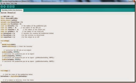
clip_image007

// Upload this code to your Arduino
#include <IRremote.h>
int RECV_PIN = 11;
IRrecv irrecv(RECV_PIN);
decode_results results;
unsigned long CurrentValue = 0;
unsigned long StoredCode = 0;
const int buttonPin = 6;     // the number of the pushbutton pin
const int ledPin =  4;      // the number of the LED pin
const int outputPin =  3;      // the number of the output LED pin
const int relayPin =  2;      // the number of the relay pin
int buttonState = 0;         // variable for reading the pushbutton status
int RecordState = 0;         //is the reciever in record mode
int outputState = 1;         //is the output on or off
void setup()
{
  Serial.begin(9600);
  irrecv.enableIRIn(); // Start the receiver
    // initialize the LED pin as an output:
  pinMode(ledPin, OUTPUT);    
  // initialize the pushbutton pin as an input:
  pinMode(outputPin, OUTPUT);    
  // initialize the pushbutton pin as an input:  pinMode(buttonPin, INPUT);   
  pinMode(relayPin, OUTPUT);    
  // initialize the pushbutton pin as an input:  pinMode(buttonPin, INPUT);   
}
void loop() {
   // read the state of the pushbutton value:
buttonState = digitalRead(buttonPin);
   // if a signal is detected, store the value
if (irrecv.decode(&results)) {
  CurrentValue = (results.value);
   // if the recieved value equals the programed value, then toggle the output state
  if(CurrentValue == StoredCode) {
      outputState = !outputState;
   }
   // if the record mode is activated store the current value as the programed value
  if (RecordState == 1) {
    StoredCode = CurrentValue;
    RecordState = 0;
    digitalWrite(ledPin, LOW);  
    Serial.println(StoredCode);  //displays stored code for reference
   }
   // Receive the next value
  irrecv.resume();
}
else //if no signal is detected, then the current value is 0
{
  CurrentValue = 0;
}
  // check if the record button is pressed.
  // if it is, the buttonState is HIGH:
if (buttonState == HIGH) {   
  //wait for the button to be released
  while (buttonState == HIGH) {
    buttonState = digitalRead(buttonPin);
  }
   //turn on the LED to indicate that record mode is on
    digitalWrite(ledPin, HIGH); 
    RecordState = 1;
}
   //set the appropriate output state
if(outputState == 1) {
      digitalWrite(outputPin, HIGH);
      digitalWrite(relayPin, HIGH);
}
else {
        digitalWrite(outputPin, LOW);
        digitalWrite(relayPin, LOW);
}
}

Step 4: The Circuit

clip_image008

clip_image009

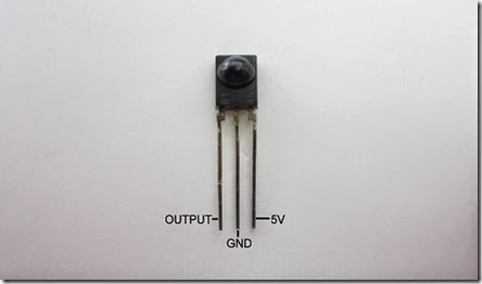
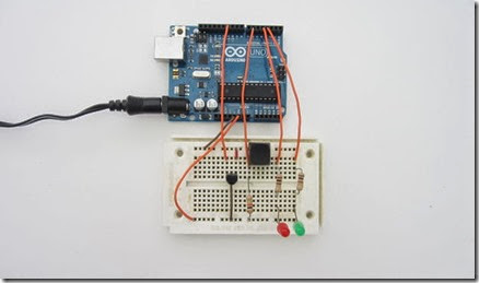
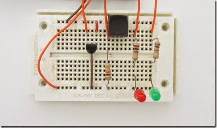
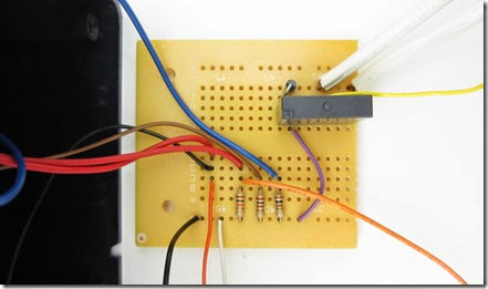
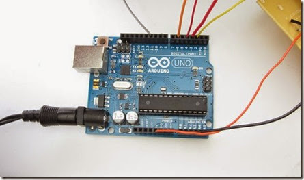
This circuit uses a 38 kHz Infrared Receiver Module to detect the signal from the remote. The right pin of this connected to 5V. The middle pin is connected to GND. The Left pin connects to digital pin 11 on the board.

The circuit also has two indicator LEDs. One indicates that the receiver is in programming mode and the other indicates whether the output is on or off. One end of each LED is connected to GND. The other end is connected to a 100 ohm series resistor. The resistors are then connected to digital pins 3 and 4.
A momentary switch is used to set programming mode. One end of the switch is connected to 5V. The other end of the switch is connected to digital pin 6 and a 10 kohm resistor. The other end of the resistor is connected to GND.

An optional relay/relay shield can be connected to digital pin 2 and GND.

You can add any additional outputs that you want. This can let you control multiple devices or multiple functions on the same device.

Step 5: Test the Circuit on a Breadboard

clip_image010

clip_image011

clip_image012

clip_image013

clip_image014

It is always a good idea to test your circuit on a breadboard before soldering it together.

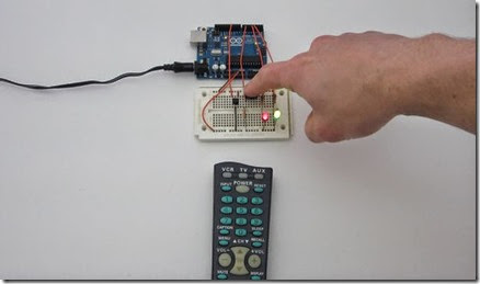
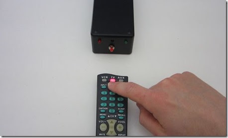
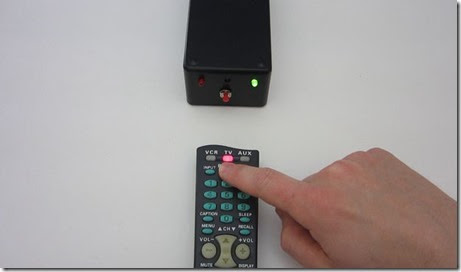
When the Arduino is powered, the output indicator (green) LED should turn on. This indicates that the output at pin 2 is HIGH and can be used to activate another circuit. To program the receiver, press the button. When the button is released, the programming mode indicator (red) LED will turn on.

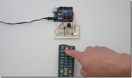
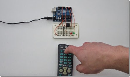
Now point your remote at the receiver module and press a button. If the Arduino registered the signal, the programming mode LED will turn off. The receiver is now programmed. Pressing this button on the remote again will cause the output at pin 2 to toggle between off and on. The output state is indicated by the LED.

You can use the signal from pin 2 to activates another circuit directly or you can use a relay/relay shield to turn an appliance on and off.

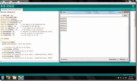
If you connect the Arduino to your computer you can use the serial monitor function to observe the value for the signals that you are programming.

Step 6: Solder the Circuit Together on a Printed Circuit Board

clip_image015

clip_image016

After testing the circuit on a breadboard, you can solder it together on a printed circuit board. The IR receiver module, the switch and the LEDs would be mounted to the housing. So I connected them to the board with jumper wires.

I added a small relay that would be activated by the output of pin 2. In most cases you will want to connect a relay driver circuit. This is because the maximum output of an Arduino digital pin is 40 mA and most relays require more than this to operate. However, I found a relay that only required 25mA to operate. So I was able to connect it directly to the digital pin. It is always a good idea to attach aflyback diode across the terminals of the coil of a relay. This helps to protect against voltage spikes when the relay is turned off.

The relay can act as a general switch and activate just about anything. In this case, I attached an extension cord. This will allow it to act as a remote controlled outlet. Always check to make sure that your relay is rated high enough for your intended load.

Step 7: Mount the Circuit in an Insulated Housing

clip_image017

clip_image018

clip_image019

clip_image020

clip_image021

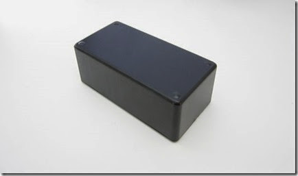
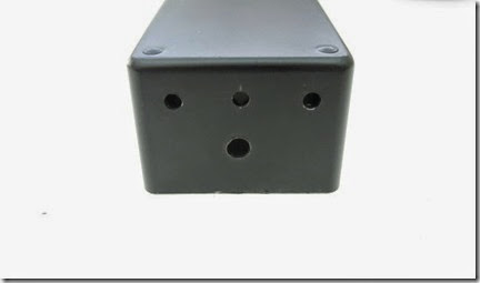
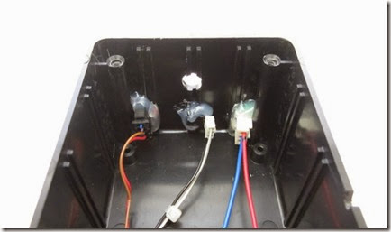
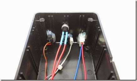
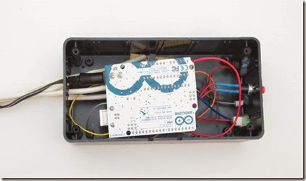
Now you need to find a good insulated housing to hold your project. I used a 6x3x2 plastic project housing from RadioShack. On one end, I drilled two holes from the LEDs, one hole for the IR receiver and one hole for the switch. Then I made holes in the opposite end for the Arduino power cord and the extension cord.
I used hot glue to secure the LEDs and the Receiver. The switch was held in place with its own nut and lock washer. You can also use hot glue to secure loose wires and to hold the boards in place.
Be very careful not to accidentally pull any wires out of the Arduino as you are fitting everything into the housing.

Step 8: Use Your Remote Controlled Switch to Activate Appliances and Other Electronics

clip_image022

clip_image023

clip_image024

clip_image025

clip_image026

clip_image027

clip_image028

clip_image029

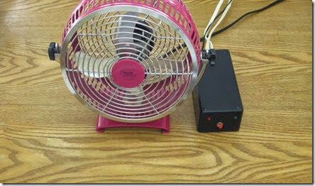
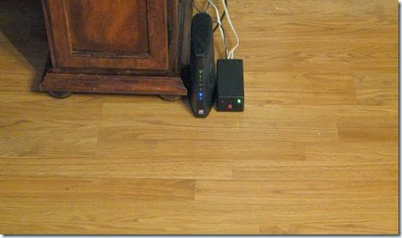
Plug in the power supply for the Arduino and it will automatically turn on. Then plug the male end of the extension cord into an outlet and plug the device that you want to control into the female end of the extension cord. The device should turn on.

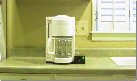
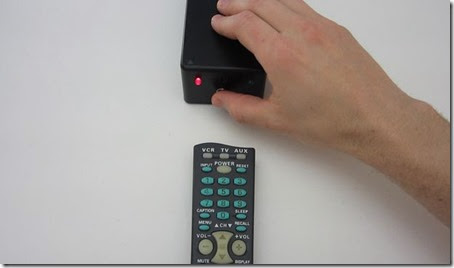
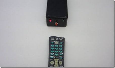
To program the receiver, press the red button. The red light will turn on. Then point your remote at the receiver and press a button. If the Arduino registered the signal, then the red light will turn off. Now you can use that button to turn the attached device on and off.

You can use this to remotely control lights, fans or even your coffee maker.

Step 9: Manually Insert IR Values into the Arduino Code (optional)

clip_image030

If you plug the Arduino into your computer, you can use the Serial Monitor tool to view the value of the IR signals for the various buttons on your remote. This gives you the option of manually inserting these values into the code. By doing this you can program responses to multiple buttons. It also means that you will not have to reprogram the receiver whenever the power is disconnected.

Taken From: http://www.instructables.com/id/Control-Any-Circuit-With-a-TV-Remote-and-an-Arduin/

https://www.youtube.com/watch?v=tvRLz4RLoeo

Thursday, April 3, 2014

Windows Concurrent Remote Desktop (RDP)

Professional and Ultimate editions of Windows come with a built in Remote Desktop (RDP) feature that allows you to access your machine remotely while away from home or the office. Unfortunately, it is limited by default to one concurrent user per session, meaning that if someone remotely connects to the computer, whoever was logged in at the moment will be automatically logged off, even if the user is physically at the computer.

This is not a technical limitation but rather a licensing one. Case in point, Remote Desktop in server editions of Windows by default supports two concurrent connections to remotely troubleshoot or administer a computer. More users can connect simultaneously, too, as long as the machine can handle it with the resources it has available and you have the required client access licenses for that particular server.

However, there are a few reasons why concurrent sessions would come in handy for power users not necessarily running a server. For example, if you have a dedicated Media Center PC running in the living room, you'll be able to remotely access all files on the machine without interrupting the person watching TV.

Or if you are sharing a computer with other users, concurrent Remote Desktop sessions will allow more than one person use that system under a different or even the same user account, without kicking each other off. By patching a file called termsrv.dll, located in %SystemRoot%System32, this is possible in all editions of Windows 7, Windows Vista and Windows XP.

clip_image001

Download: UniversalTermsrvPatch_20090425.zip (zip File, 66 KB, mirror #2)

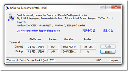
Fortunately for us, Internet user DeepXW already did all the dirty work a while ago and posted his Universal Termsrv.dll Patch for anyone to get their hands on. Simply download and unzip the file, then run the corresponding file as administrator (right-click the exe file and select Run as Administrator). For 32-bit systems use UniversalTermsrvPatch-x86.exe and for 64-bit versions of Windows use UniversalTermsrvPatch-x64.exe.

You should see a window like the one above where you can patch termsrv.dll to remove the Concurrent Remote Desktop sessions limit and restore the original file at any time (a backup file is located at 'windowssystem32termsrv.dll.backup'). After applying the patch, restart your system and you are ready to go.

clip_image002

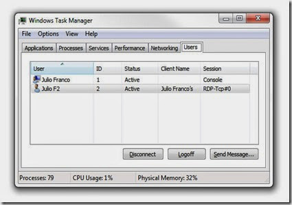
To test it out simply leave a session open on to the PC where you applied the patch, then from another machine try and connect to the computer remotely. If all goes well both users will be logged on and active.

· Contact the author: Jose Vilches

Taken From: http://www.techspot.com/guides/485-windows-concurrent-sessions/