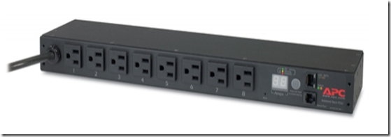
When I started preparing for my CCNP SWITCH exam I bought some switches and set them up in my basement. After a couple of labs I realized I did a lot of trips to the basement to start / stop / restart the equipments. That’s when I started searching for remote controlled PDU, like this:
these are great but are very expensive for personal use (normally used in datacenters).
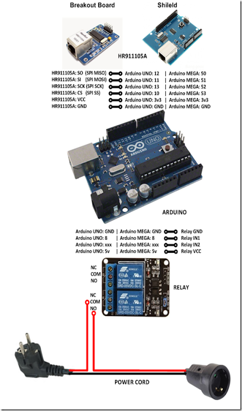
I already had an Arduino, so I started searching for a relay and cheap Ethernet NIC (the one on the arduino store was way to expensive), and I found the components below.
I put the components together and started programing the EPLUG program.
EPLUG is basically a small telnet Command Line Interface (CLI) that you can use to control multiple relays atached to Power Plugs. With this you can turn ON and OFF just about any electronic appliance you own from any device with telnet (PC, SmartPhone, Tablet, etc), using your Home Network or the Internet.
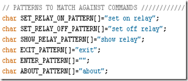
EPLUG was built as a framework that can be used for other projects. You can easily change the commands syntax by changing the text on the command patterns and add new commands by adding a new "else if(..){...}" statements on the "loop()" function.
Components
Relay Model: SRD-05VDC-SL-C

This relay board uses opto-couplers / opto-isolators to drive the relays, these isolate your Arduino from the relays, protecting it from voltage spikes. For more information check these videos:
Ethernet NIC Model: HR911105A
Shield Version

Breakout Board Version
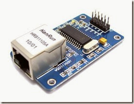
when i bought these components i did some basic tutorials on wich we are going to build upon, so you should check them out for more details or to test each component individually:
EPLUG Prototype
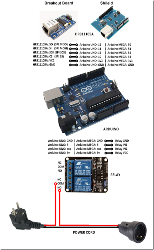
The complete build looks like this:
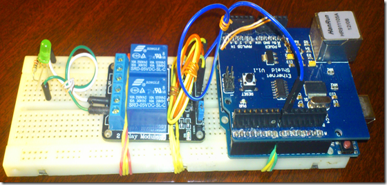
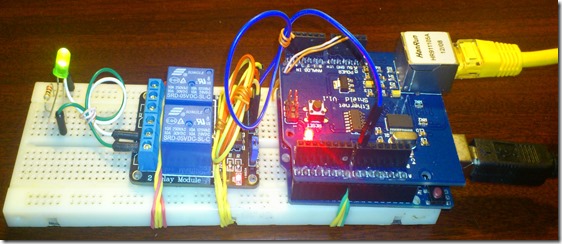
for the prototype I replaced the POWER CORD with an LED for testing:
my prototype looked like this:
The next step is to add the IP stack (uIP) for the Ethernet NIC (HR911105A).
You basically download the uIP IP stack here:
extract it, and put it on the arduino libraries folder
EPLUG as a Framework
The EPLUG program a simple and flexible Command Line Interface (CLI):
it receives the command on the function:
- rcv_cmd(cmd, cmd_len)
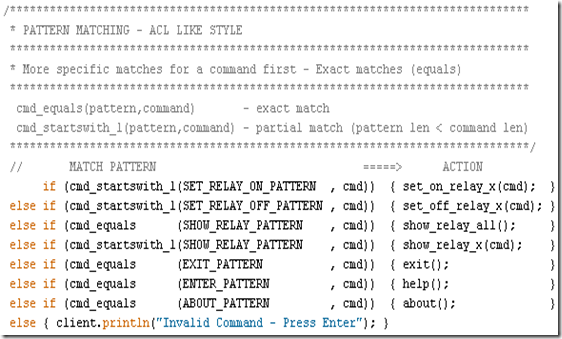
and matches them against the predefined patterns:
using the following functions:
- cmd_equals (pattern,command) - exact match
- cmd_startswith_l (pattern,command) - partial match, allow the commands to have a option (in this case the pin number)
and when it finds a match it executes an the function/actions for the corresponding command, as you can see below:
the structure above makes EPLUG very flexible, so that it’s easy to:
- Change the current commands text
- Add more commands (just add an else if (..){...} line)
my goal was to build EPLUG as a Framework for future projects.
For example if you want to do a program to set LEDs ON/OFF LEDs, you just need to change the patterns and the action functions and in 10 minutes or less your program is done.
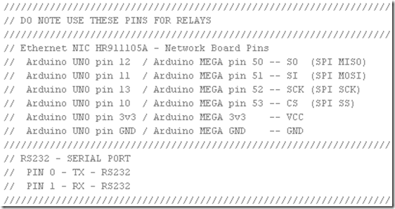
Available Pins for Relays
There are some pins that that you should not use:
so you should only use the following pins:
- Pin 2
- Pin 3
- Pin 4
- Pin 5
- Pin 6
- Pin 7
- Pin 8 – I used this PIN
- Pin 9
you can basically plug up to 8 relays to an Arduino UNO and controll them with the EPLUG program.
Loading EPLUG
Get the EPLUG code here:
- https://github.com/myhowtosandprojects/EPLUG/blob/master/EPLUG.ino
- https://github.com/myhowtosandprojects/EPLUG
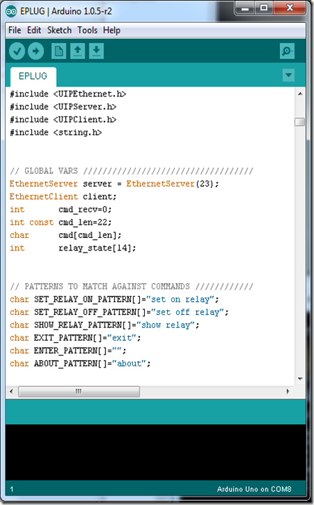
Open the EPLUG code on the Arduino IDE:
To upload the program to Arduino just press:
after compiling and uploading the IDE show the program size, and it should be 25.xxx bytes.
Problem: I found out that, for some reason, if the program is a bit over 26.000 bytes the Ethernet NIC doesn’t work properly. The maximum on the Arduino UNO is 32.256 bytes so this shouldn`t happen.
Testing EPLUG
First you need to find the IP of the Arduino NIC and make sure it’s on the correct network (your LAN network), you can do that here:
now telnet to it:
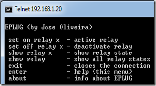
press ENTER to start the CLI and show the options:
to set the “relay” (for now the LED) on you type:
you should get something like this:
Problem: After some time (1-3 min) the LED goes off for no aparent reason. After some research I found that this behavior is the the Arduino’s In System Programer (ISP) checking if you want to reprogram Arduino from your PC (basically resets Arduino). The solution is very simple, you just don’t power the Arduino from your PC, you use a power supply.
to show the “relay” (LED) current state, you type:
to show all the “relays” (LEDs) current state, you type:
to set off the “relay” (LED), you type:
to show info about EPLUG, you type:
to close the telnet session, you type:
Putting It All Together
Now we can replace the LED with the POWER CORD, and use/test EPLUG in the real world.
In this diagram the POWER CORD starts OFF, if you want it to start ON just change the wire on the relay from NO (normally open) to NC (normally closed).
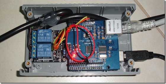
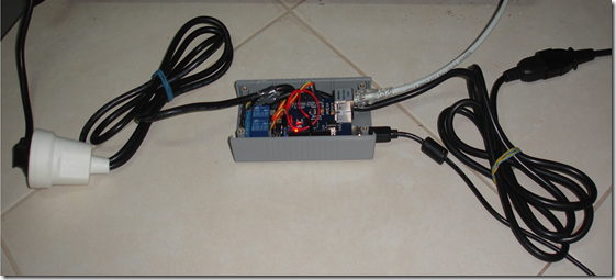
My build looked like this:
now you can test/use it in the real world, check out my test video:
Next Steps
- Add an internal USB power supply
- Make it a lot smaller/cheaper (microntroller + breakout board)
- Make a version with GSM aka GPLUG (SMS or GPRS)
- Make a version with Radio modules aka RPLUG
- Map relays to numbers different from the PINs
- Save the pins state to a non-volatile memory (EEPROM)
- Add a current sensor
Check out my makers community at:
