Thursday, October 31, 2013

How To Install JAVA on Debian (via Repository)

HOW TO INSTALL ORACLE JAVA 7 IN DEBIAN VIA REPOSITORY

A quick tip for Debian users who want to install and stay up to date with the latest Oracle Java 7 (JDK7): the WebUpd8 Java 7 PPA works on Debian too since the package is just an installer and all you have to do is manually add the PPA repository to the Software Sources.

As a reminder, the Oracle Java 7 PPA repository does not host any Java files but only an installer that automatically downloads and installs Oracle Java 7, like the flashplugin-installer package for instance.

To add the WebUpd8 Oracle Java PPA repository to the Software Sources in Debian (tested on Debian Squeeze, but it should work with any Debian version), use the following commands:

su -

echo "deb http://ppa.launchpad.net/webupd8team/java/ubuntu precise main" | tee -a /etc/apt/sources.list

echo "deb-src http://ppa.launchpad.net/webupd8team/java/ubuntu precise main" | tee -a /etc/apt/sources.list

apt-key adv --keyserver keyserver.ubuntu.com --recv-keys EEA14886

apt-get update

apt-get install oracle-java7-installer

exit

clip_image002

clip_image004

And that's it, Oracle Java 7 (both JDK7 and JRE7) should now be installed and you should receive automatic updates with future Oracle Java 7 versions, under Debian.
Update: the current JDK version in the PPA is Oracle Java 7 Update 10 (7u10).

Setting Java environment variables

To automatically set up the Java 7 environment variables, you can install the following package:

sudo apt-get install oracle-java7-set-default

If you've already installed oracle-java6-set-default or oracle-java8-set-default, they will be automatically removed when installing oracle-java7-set-default (and the environment variables will be set for Oracle Java 7 instead).
For installing Oracle Java 7 in Ubuntu, see: Install Oracle Java 7 in Ubuntu via PPA Repository

Taken From: http://www.webupd8.org/2012/06/how-to-install-oracle-java-7-in-debian.html

Friday, October 18, 2013

Raspberry PI – BerryBoot Bootloader (Multi OS + USB)

BerryBoot v2.0 – bootloader

Universal Operating System Installer

clip_image002[4]

For people short on SD cards: Berryboot is a simple boot selection screen, allowing you to put multiple Linux distribution on a single SD card.

In addition it allows you to put the operating system files on an external USB hard drive instead of on the SD card itself.

Download link Berryboot for the Raspberry Pi: berryboot-20130908.zip

To install: extract the contents of the .zip file to a normal (FAT formatted) SD card, and put it in your Raspberry Pi. This can be simply done under Windows without any special image writer software.

Once you start your Pi it will start an installer that reformats the SD card and downloads the operating systems files from the Internet.

Other devices

In addition to running on the Raspberry Pi, Berryboot also supports Android tablets, TV sticks and boards that have an Allwinner A10 processor.
For more information see the BerryBoot A10 page

Changelog

→ Moved to: Berryboot Changelog

Walkthrough

clip_image004[4]

If your Pi is connected to the Internet BerryBoot will try to detect your location based on your IP-address, and set the right timezone automatically. Verify that it is correct and press “ok”

clip_image006[4]

Select where you want to store the operating system files, and press “format” You can install the operating system files on the SD card itself or an external USB stick/disk. Be aware that if you choose an external drive, the files of the operating system will be stored there, but you still need to keep the SD card in the Pi to boot from.

WARNING: all existing files on the disk will be erased.

clip_image008[4]

Select which operating system you want to install. You can add more later.

clip_image010[4]

It will download the files from the Internet automatically.

clip_image012[4]

In the Berryboot menu editor you can install more operating systems, rename them, delete them, etc. Press “exit” to exit the editor and start using the operating system you installed.

HDMI CEC support

When attached to a HDMI TV, you can also use the arrows on your TV remote to select an operating system to boot, instead of using your keyboard or mouse.

Available options in menu editor

§ “Add OS” (or CTRL+A on keyboard, red button on TV remote)
Single click to download additional operating systems from the Internet.
Hold down your mouse button over the “Add OS” button and select “copy OS from USB stick”, to install an operating system saved on USB stick.

§ “Edit” (or ENTER on keyboard)
Change the name of the selected operating system.
You used to be able to change the memory split setting here as well, but for new installations (that have CMA enabled) this is no longer used.

§ “Clone”
Creates a copy of the selected operating system.
It is possible to create either a copy that includes the file system changes you made, or create a copy of the original operating system image as downloaded from the Internet.

§ “Backup”
Creates a backup of a single operating system or all of them to a USB stick, or SD card (requires USB SD card reader).
Backups of individual images can be restored by holding down the “add OS” button and selecting “copy OS from USB stick”

§ “Delete” (or DEL on keyboard)
Deletes the files of the selected operating system.

§ “Make default”
Makes the selected operating system the default. On boot, this operating system will be started automatically unless another is selected within a number of seconds.

§ “Exit” (or ESC on keyboard)
Exits the menu editor.

Advanced options

clip_image014[4]

Click on the ”»” button to the right of the screen to see all options.

§ “Advanced configuration”
Editor for configuration files such as cmdline.txt and config.txt

When using a Raspberry Pi you can specify kernel parameters and Berryboot parameters in cmdline.txt (use uEnv.txt if you have another device).
Special Berryboot parameters:

bootmenutimeout=<number of seconds> - number of seconds before default operating system is started. nobootmenutimeout - do not start the default operating system automatically.

In config.txt advanced overscan, HDMI and overclocking settings can be specified. See the RPIconfig page on eLinux.org for details.
Note that overclocking is known to cause SD card filesystem corruption, so only use that when you are using an USB stick or drive as storage and know what you are doing.

§ “Console”
Activates a console on tty2
Press CTRL+ALT+F2 to access, username “root”, no password.

§ “Set password”
Password protects access to the menu editor, so that unauthorized users cannot delete or edit the operating systems.

§ “Repair filesystem”
Performs a file system check and repair. Attempts to repair file system corruption. Can perform a lot of writes to the SD card, so you might want to make a backup of important files first.

Alternative installation method using disk image

If you are experiencing problems unpacking the installation files to a FAT formatted SD card (the easiest and recommend installation method), you can alternatively use a tool like Win32diskimager or dd to write this disk image to the card.
The disk image is meant to install Berryboot on another device, but it includes the Raspberry Pi boot files as well.

More information

For advanced users:

§ Headless installation (install Berryboot without display attached, using VNC)

§ Adding your own custom operating systems to the menu

§ Berryboot source code on Github

§ Report bugs

Taken From: http://www.berryterminal.com/doku.php/berryboot

Raspberry Pi – Low Cost HD CCTV Camera

Raspberry Pi as Low-Cost HD Surveillance Camera

By Christoph Buenger, DaSpors, 11 Oct 2013

Introduction

This article describes how to build a surveillance cam based on a Raspberry Pi micro-computer which records HD video when something moves in the monitored area. Live picture can be viewed from any web browser, even from your mobile while you're on the road.

What you will get:

· See live stream in any web browser from anywhere

· Record any motion into video file 

Usually, such a cam will cost you around US$2.000, but with the result from this article, you will get such a cam for only about US$100.

Background

Have you ever heard of Raspberry Pi? It's a low-cost micro-computer that is able to run Linux and has endless extension possibilities. It cost only about US$35 and opens up endless possibilities of what you can build with it. The official website can be found at http://www.raspberrypi.org/

Hardware components 

We need some hardware for this project. This is a list of the major things we need: 

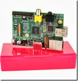
· Raspberry Pi Model B:  This is the larger model of the Raspberry computer system with 700MHz and 512MB Ram. It supports HD video. Start here to see where you can order it in your country: http://www.rs-components.com/raspberrypi. Cost: about US$35 clip_image001
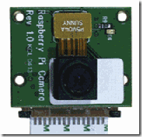
· Raspberry Pi Camera Module: This module was specially build for the Raspberry micro-computer. It has a connector to be plugged directly into the Raspberry board and supports HD video up to 1080p. The website http://www.rs-components.com/raspberrypi will show you where you could order it from your country. I.e. http://www.alliedelec.com/lp/130513rasocameramodule/ ships this camera in the US for only US$29
clip_image003

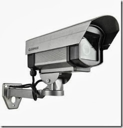
·  A housing for the camera:  you don't need to buy a high-price-housing for your Raspberry. There are loads of very cheap fake security cameras available which perfectly fit our needs here. Search the web for "surveillance camera dummy" and you will find loads of housings for your new camera for only a few dollars. I.e. this one will do the job: http://amzn.to/15XLaAj for only US$9. We have ordered this camera housing for about 20€ in Germany that had enough space for all the components: http://amzn.to/19CTEaN. You can use any camera housing, but only be careful about the size of the housing so that the Rasperry board will fit in there. The dimensions of the Raspberry board are 85.6 x 53.98 x 17 mm (approx 3.37 x 2.13 x 0.67 in). 
clip_image004

· Power supply: The Raspberry computer does not come with any power supply, you have to get one on our own. Any power supply with a micro-USB plug can do the job as long as it supplies 1A of power. We have ordered such a power supply plus a USB-to-micro-USB cable for about US$15: http://www.alliedelec.com/Search/ProductDetail.aspx?SKU=70232557
clip_image005

· SD card: as the Raspberry Pi does not have any storage on board, you need to add some so that you can install and run the operating system for this device. Any SD or microSDHC should do the job, but we recommend using a Class 10 SD card. It's only around US$7
clip_image006

· To connect this cam to your network, you also need some kind of network connection. One possibility is to use a LAN connection, but you would need to put LAN cable to the point where you want to mount the camera. A better alternative is such a wifi USB adapter for only about US$10:
clip_image007

That's all: for about US$105 we have all the hardware we need to build this HD surveillance cam. 

Install Raspbian 

At first, you should install the OS and software to the Raspberry Pi before mounting it all together. An OS is the basic operating system software that tells the Raspberry hardware what to do. Linux is perfect for this. We have chosen Raspbian, as it's one of the most advanced OS for the Raspberry with loads of help and tutorials on the internet.

You need to prepare the SD card to be able to run Raspbian on the Raspberry: this excellent tutorial from Adafruit will explain the necessary steps.

Now temporarily connect your Raspberry Pi board to LAN cable, a monitor (HDMI TV works out of the box, but a HDMI-to-DVI cable like this will do the job as well) and a USB keyboard for the basic setup.

Insert the prepared SD card with the Raspbian installer on it and attach the power supply.

The Raspberry should boot up and guide you through the setup process as explained in this Adafruit tutorial. After this, you should have a basic Raspbian OS running.

Be sure to enable SSH in Raspbian so that you are able to control the Raspberry device also when there is no monitor and keyboard attached. 

Connect via SSH 

Now that the basic setup is done, you should connect to your Raspberry device from your computer. You can connect to Linux console from any computer in your local network and control it like you where sitting directly in front of it. This is very important as once mounted far away from your desktop, you need to be able to make updates and change the configuration of this camera any time later without the need to detaching it from the wall and bringing it back to your desk.

Remember that this cam is not just a dump cam device but a very powerful computer with Linux OS running on it. It's not limited to what we explain in this article now; it will follow any development in software so that you will be able to install updated software and more modules any time later.

First, you need a software to connect to the Linux console on the Raspberry. For Windows, you will need the extra (free) software PuTTY. Download it from the PuTTY website, install it and connect to your Raspberry Pi device:
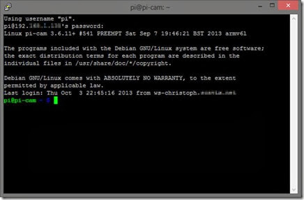
clip_image008

From now on, you don't need any monitor and keyboard attached to the Raspberry anymore. 

Enable wifi 

If you want to run this camera with a wifi USB dongle (like we've suggested above), you will need to do some quick additional steps to make wifi work on the Raspberry: 

From the console (PuTTY window), edit the network properties of the Raspberry:

sudo nano /etc/network/interfaces

Now add these lines at the end of the file (or change existing lines to match these):

allow-hotplug wlan0

iface wlan0 inet dhcp

wpa-ssid "YOUR NETWORK SSID"

wpa-psk "WIFI PASSWORD"

(Fill in the SSID and password for your wifi network)

Reboot the Raspberry with this command and see if it correctly connects to your wifi network:

sudo reboot

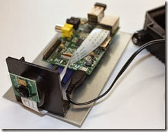
Put the hardware together 

Now it's time to assemble all the hardware components together into the housing. Depending on the housing, this should not be a too complicated job:
clip_image010

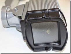
As our housing had a very large glass window at the front, we have closed it with a black paper with a hole in it:
clip_image011

This also has the advantage that the red recording light of the Raspberry Pi camera module is not visible anymore. If you like the camera recording led to be visible, don't cover it. Whenever the camera is detecting any motion or is recording, the led light will glow in a very bright red.  

Installing the motion detection software 

A very good (and free) motion detection/surveillance software with many configuration options is motion. As the current version of this software does not support the Raspberry camera module yet, we've followed this special instructions to download and install a special build with support for this camera module. We're pretty sure that the official build of motion will shortly also support the Raspberry camera module as well.

A very important command to edit the motion configuration file is

sudo nano /etc/motion.conf

We've made some changes to the motion.conf file to fit our needs. Our current motion.conf file can be downloaded here: raspberry_surveillance_cam_scavix.zip

Some of the main changes are:

Make sure that motion is always running as a daemon in the background:

daemon on

As we want to use a high quality surveillance video, we've set the resolution to 1280x720:

width 1280

height 720

We don't need real-time video, 2 pictures per second are totally ok for our needs:

framerate 2

This is a very handy feature of the motion software: record some (2 in our configuration) frames before and after the motion in the image was detected:

pre_capture 2

post_capture 2

We don't want endless movies. Instead, we want to have max. 10 minutes slices of the motion videos:

max_movie_time 600

Enable access to the live stream from anywhere. Otherwise only localhost (= the Raspberry device) would be allowed to access the live stream:

stream_localhost off

If you want to protect the live stream with a username and password, you should enable this:

stream_auth_method 2

stream_authentication SOMEUSERNAME:SOMEPASSWORD

All configuration parameters are explained in detail in the motion config documentation.

Save videos on Windows shared folder

As the SD card of the Raspberry Pi is a pretty limited resource, we've decided to let the Raspberry cam store the videos on one of our Windows Servers. This is pretty easy:

First share a folder from some Windows machine. Just follow some guides on the internet if you've never shared a folder from a Windows machine before.

Then open the fstab configuration on your Raspberry from a PuTTY console or directly from the device:

sudo nano /etc/fstab

Now add an extra line with the configuration of your Windows network shared folder: 

//YOURSERVERNAME/YOURSHAREDFOLDERNAME /mnt/camshare cifs username=YOURSHAREDFOLDERUSERNAME,password=YOURSHAREDFOLDERPASSWORD,iocharset=utf8,file_mode=0777,dir_mode=0777 0 0

After a reboot, the Raspberry should have an extra folder /mnt/camshare mounted to the Windows shared folder. You should now set in your motion.conf

target_dir /mnt/camshare

so that motion saves all movies to the shared folder on the Windows machine.

Fix motion autostart 

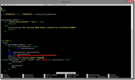
We had some trouble that motion was not automatically started on a reboot of the Raspberry. We've found out that this was because the mounted folder of the Windows machine was not yet ready when motion tried to access it.

A very quick fix solved our problem:

Just edit the motion file with

sudo nano /etc/init.d/motion

and add the line

sleep 30

to the start-sequence:
clip_image012

Our changed /etc/init.d/motion script can be found in the attached raspberry_surveillance_cam_scavix.zip

Mounting the camera 

After all these steps, you can finally mount the surveillance camera to the destination point.
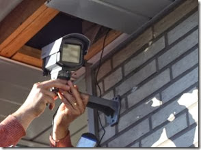
clip_image013

Some helpful hints: 

· Be sure to place the power supply in a dry and safe place

· Keep an eye on the wifi signal: if you mount the camera out of range of the wifi, it won't be able to send any video and motion videos  

Accessing the live stream

Now you can access the live stream from the camera from any browser via the url http://IPADDRESSOFRASPBERRY:8080 

Where 8080 is the port that we've configured for our stream in the motion.conf file. See your own configuration setting "stream_port" in motion.conf for the port.

We've found out that Google Chrome 30 (not even on iOS) was not able to play this stream directly due to a bug in the underlying Chromium project. But any other browser like Internet Explorer, FireFox, Safari and even VLC media player was able to show the live stream of the camera.
A workaround for this is to create a simple html file that contains one large image with the stream-url of the camera. See the file cam.html from raspberry_surveillance_cam_scavix.zip. This way, Chrome can show the live stream as well. Let's hope that Chrome will fix this issue in their browser. 

Access live stream from anywhere 

To make the live stream accessible from anywhere, you will need to enable some kind of dynamic domain services to your local network. This will enable you to always be able to connect to your local IP address from the outside even if your local IP address changes (over here in Germany, every private DSL ip address changes every 24 hours). 

Such a (free) service enables you to access your Raspberry from anywhere even if your ip address changes. A very good service we're using for some years now is dyn.com. They have some free services and are integrated in many routers. 

Once you have set up the dynamic ip url, you can access the camera stream from anywhere in your browser (i.e. http://YOURDYNAMICDOMAIN:8080):
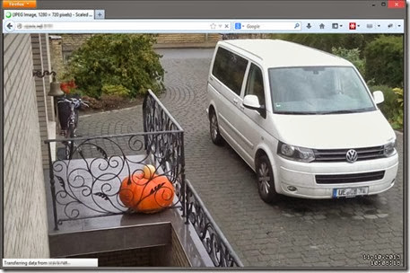
clip_image014

And this also works from the browser on your mobile device:

clip_image015

Advanced steps 

There are a thousand things you can do with such a surveillance cam basic setup now. How about sending Growl notifications when some motion was detected? This guide explains how to add this functionality easily. 

Or you could easily add a temperature-sensor to the cam. It's only a few bucks and can be integrated very easily

We're currently working on integrating the live stream into MediaPortal server so that we can switch to a TV channel to see the live stream from the cam in our office.

If you want extra security, you could also add a battery pack to the camera. Be sure to buy one that is able to charge simultaneously while powering the Raspberry. This would enable you to detect if some bad guy cuts the power strips of your camera and send some alert messages to you (i.e. SMS or email) including the video of the disturber.

What are you going to add? Let us know!

History 

10/10/2013: Initial release of article

License

This article, along with any associated source code and files, is licensed under The Code Project Open License (CPOL)

About the Authors

Christoph Buenger

CEO Scavix Software Ltd. & Co. KG
Germany clip_image017

Scavix Software offers high quality software development and consulting. That's what customers like Intel, AMD, eBay and Sage Software trusted in the last 6 years. Be it on the desktop, in the web browser, on a mobile phone, on a tablet or on the TV: we can make your software visions come true.
Are you our next customer? Don't hesitate to contact us.

Taken From: http://www.codeproject.com/Articles/665518/Raspberry-Pi-as-low-cost-HD-surveillance-camera
Saturday, October 5, 2013

Expand Android Internal Memory with link2SD

In most of the Android phones internal memory remains low which is between 200-400MB. And in most of the cases generally the apps get installed in the internal memory so it take spaces and finally when internal memory becomes full your phone get slow or hanged. Though there is chance to install the apps in SD card but in most of the cases they get installed in the internal memory in default. So to get release from this problem the best solution is to use link2SD which let you install the apps in a separate partition of your SD card.

clip_image002

Let me show the way to expand internal memory with link2SD.

Requirements:

1. Your phone must be rooted. Rooting of your phone varies on your phone model.

2. There should have two partitions and you should backup files from the SD card.

3. Remove your micro SD card from the phone and using a SD card adapter, connect it to you computer, either directly our using an SD card reader (normaly USB)

Step 1: Create partition on SD card:

There are two ways to create partition. I recommend you to use Mini Partition Wizard Home Edition, it’s free. Linux fans use GParted.

I’m going to use Mini Partition Wizard Home Edition, but if you ruin your SD card and windows / Mini Partition, does not recognize it, use the GParted Live CD (miracle worker), if you don’t have linux installed.

Using the Mini Partition Wizard create the following partitions:

  • Primary Fat32 Partition – Your normal SD card partition (with most of the sd cards space)

  • Primary Ext2 Partition – The partition that will hold the Apps that you move from the phone’s internal memory. Mine was 1.5 GB, but it all depends on you needs and you sd card size.

  • Primary Linux Swap – Used by linux for ram extension (something like windows pagefile), it should be at least as big as you phone’s RAM, mine is 512 MB.

Note: I used primary partitions but it’s possible that extended partitions migth work (didn’t test).

image

Now that we have completed creating partition now its time to configure link2SD.

Step 2 - Configuring link2SD:

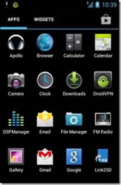
· At first download link2SD

clip_image009

· Now install the app and launch it.

clip_image011

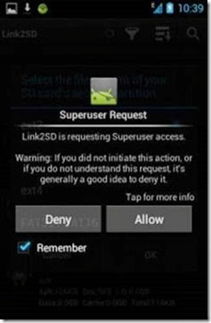
· When you launch the app it will ask to get superuser access.

· Allow the request

clip_image012

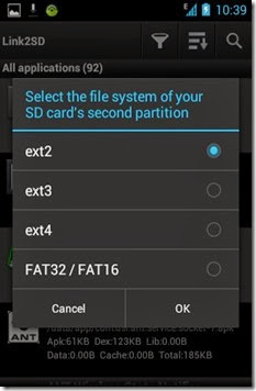
· Now it will as you to select the file system of your SD card’s second partition, select ext2 and tap OK.

clip_image013

· Now it will ask you to restart the phone, just tap OK to restart.

· After restarting your phone launch the link2SD app again.

clip_image014

· It will show you a dialogue, tap OK

clip_image015

· Now tap on the icon which you see in the screenshot and choose multi-select to select all.

clip_image016

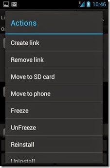
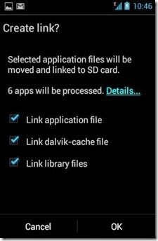
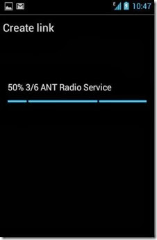
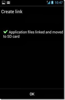
· In this step go to Actions menu and select Create link then tick all the 3 options and tap OK

clip_image017

clip_image018

clip_image019

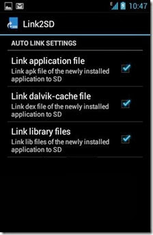
· Now configure the settings to create auto link in future.

clip_image020

clip_image021

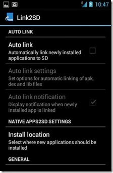
· To do this go to Menu>Setting and Auto link and tick all the 3 options.

· Now exit the apps and forget about internal memory.

clip_image022

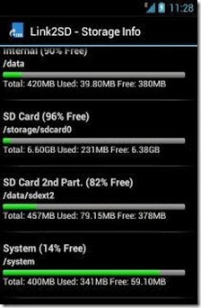
· To check memory status, launch link2SD and go to Storage Info.

Read more: http://www.androidever.com/expand-android-internal-memory-with-link2sd/#ixzz2gtFe3TfL


Based On: http://www.androidever.com/expand-android-internal-memory-with-link2sd/

Friday, September 27, 2013

Arduino PIR Motion Sensor / Detector

Make your own Arduino motion sensor / detector.  Maybe you want something to happen when you walk into a room, like have the lights turn on, or have your theme song play whenever you enter.

This tutorial will show you how to get your to Arduino sense motion around it.

Hardware used in this tutorial:

· Motion Sensor for Arduino, with wire jumpers

· Arduino board (Uno, Mega, Duemilanove, etc.)

Instructions:

If this is your first Arduino project, first go through our “Arduino: Getting Started” tutorial.

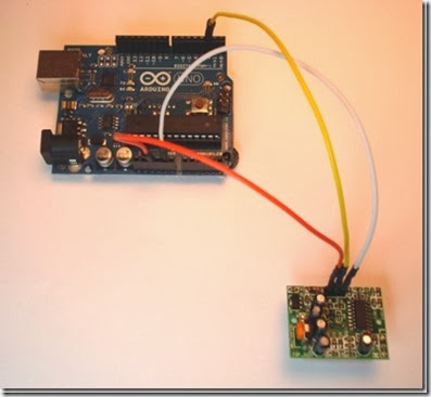
Connections:

Use the supplied male to female jumpers to make these connections:

Motion Detector

Pin

Arduino Pin

"-"

GND

"Out"

Arduino Pin 2

"+"

+5v

Like this:

clip_image001

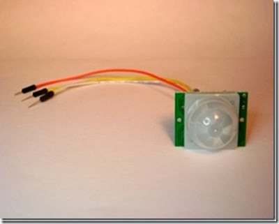
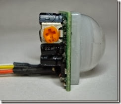
Here is the front view of the module:

clip_image002

Software:

Download the example motion sensor for Arduino software here, and unzip the file

/* 
    Motion sensor for Arduino, example code
    Tutorial: 
http://www.hacktronics.com/Tutorials/arduino-motion-sensor.html
    Copyright: Mark McComb, hacktronics LLC
    License:
http://www.opensource.org/licenses/mit-license.php (Go crazy)
*/

const byte ledPin =  13;    // LED pin
const byte motionPin = 2;   // motion detector input pin
byte senseMotion = 0;       // variable to hold current state of motion detector

void setup() {
  // set the digital pin directions
  pinMode(ledPin, OUTPUT);     
  pinMode(motionPin, INPUT);
}

void loop()
{
    // Now watch for burglers
    senseMotion = digitalRead(motionPin);
    if (senseMotion == HIGH) {    // burgler found!
      digitalWrite(ledPin, HIGH);
    } else {                      // no burgler, yet...
      digitalWrite(ledPin, LOW);
    }
}

or copy the blue text above to motion_sensor_for_arduino.pde file.

You will now have a folder called “motion_sensor_for_arduino”

Start the Arduino software and load the Arduino Motion Sensor example program by clicking File->Sketchbook->Open

Navigate to the motion_sensor_for_arduino folder and select the “motion_sensor_for_arduino.pde” file.

Transfer the Arduino Motion Sensor program to your Arduino board by clicking the “Upload to I/O board” button. After uploading, you should see the LED on the Arduino board light up whenever there is motion detected.

It is that simple to add motion detection to your Arduino project.

Remember, it takes about 60 seconds after you first power up the motion sensor before it stars to detect motion.

You can adjust the amount of time that the motion detector lights the Arduino LED by adjusting the potentiometer screw on the back of the motion sensor module:

clip_image003

Happy Hacking!

Based On: http://www.hacktronics.com/Tutorials/arduino-motion-sensor.html

Saturday, September 21, 2013

Cisco to Huawei – Essential Command Mapping

CISCO

HUAWEI

ping

ping

traceroute

tracert

show

display

show interfaces

display interface

Show ip route

display routing-table

Show ip interface

Display ip interface

Show version

Display version

Show ip bgp

Display bgp routing-table

Show clock

Display clock

Show port

Display port-mapping

Show flash

dir flash: (on user view mode)

Show logging

Display logbuffer

Show snmp

Display snmp-agent statistics

Show frame-relay pvc

Display fr pvc-info

Show users

Display users

Show terminal length

screen-length disable


undo screen-length disable

enable

Super

disable

Super 0 (number is privilege level from 0 to 3, where 3 is default and equivalent to “enable” on Cisco)

Conf t

System-view

exit

quit

end

return

Show policy-map interface

Display qos policy interface

send

send (on user view mode)

write terminal (sh run)

display current-configuration

Sh startup

Display saved-configuration

[no equivalent: shows the files  used for startup]

Display startup

Write erase

Reset saved-configuration

Write mem (or wr or copy run  start)

save

clear counters

reset (on user view mode)


Reset counters interface

?

?

telnet

telnet

Enable secret (conf mode)

Super pass cipher (system mode)

Term mon

term debu

clock

clock

no

undo

debug / no debug

debugging / undo debugging

copy running-config

Save safely

terminal monitor

terminal monitor

terminal length

screen-length disable


undo screen-length disable

terminal no monitor

undo terminal monitor

clear counters

reset counters interface

clear interface

reset counters interface

clear crypto

ipsec sa


ike sa

clear access-list counters

reset acl counter all

reload

reboot

shutdown

shutdown

boot

boot bootrom

Aaa

hwtacacs scheme

terminal no monitor

undo terminal monitor

tacacs-server

hwtacacs scheme (in conf  command)

snmp-server

tftp-server (in conf command)

router bgp

bgp

Router rip

rip

ip tacacs

hwtacacs nas-ip (this  command doesn’t exist !!!)

mtu

Mtu (this command doesn’t exist !!!)

clear ip cef

reset ip fast-forwarding

clear ip route *

reset ip routing-table statistics protocol all

Clear ip bgp

Reset bgp all

Show tech

display diagnostic-information

Sh ip nat translation

Display nat session

Show Controller

display controller (but not relevant for non-modular chassis)

show dsl int atm 0

display dsl status interface Atm 2/0

sho atm pvc

Display atm pvc-info

debug pvc nego

Debug atm all (very dangerous – might crash router)

sho crypto isakmp sa

Display ike sa

sho crypto isakmp key

Display ike peer

sho crypto isakmp police

Display ike proposal

Taken From : http://lifeoflogs.blogspot.pt/2011/04/cisco-vs-huawei-essential-command.html

Monday, September 9, 2013

Step 2 - Sony Xperia Arc S - Howto Install Clockworkmod

clip_image001[1]

So you have rooted your Sony Xperia Arc S and now want to flash a custom ROM? It’s definitely possible. But in order to do that, you’re gonna need a custom recovery, preferably ClockworkMod Recovery to allow installation of such ROMs and Mods. While the recovery provides options to flash new ROMs, it also lets you make backups of your current ROM to share with your friends or maybe use it to restore your device to the working condition if you’ve messed up with it. This guide shows how you can install ClockworkMod Recovery on your Xperia Arc S device and enjoy a whole new world of custom ROMs!

I. Before You Begin:

1. You must have rooetd your device before doing this procedure. Check out our procedure on Step 1 - Sony Xperia Arc S - Howto Root to root your device.

2. This works on Windows based PCs only.

II. Downloading Required Files:

1. RecoverX (Download link’s given in the first post)

RecoverX Mirror

III. Installing ClockworkMod Recovery on the Sony Xperia Arc S:

1. Place the RecoverX Tool archive onto your Desktop.

2. Unzip files from the archive over to your Desktop.

3. Enable USB debugging on your device by going to Menu>>Settings>>Developer options>>USB debugging.

4. Connect your device to your PC using the USB cable.

5. Double-click on the RecoverX’s executable file and it’ll launch.

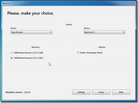
6. Select Sony Ericsson from Brand dropdown menu in the tool.

7. Select Xperia Arc S from the Device dropdown menu.

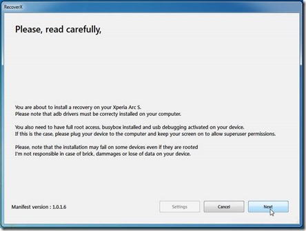
clip_image003

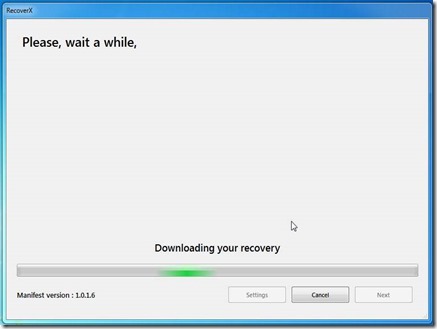
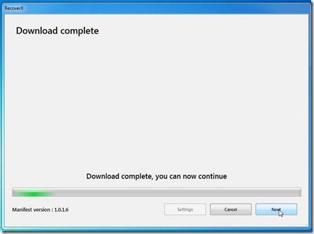
8. Now hit the Next button and it’ll start flashing the recovery on your device.

clip_image005

clip_image007

clip_image009

clip_image011

clip_image013

9. Follow any prompts you see on your screen.

10. Once it’s done, reboot your device.

11. You’re all set! Excellent! Your Xperia Arc S has been successfully equipped with CWM Recovery and you now have endless possibilities to customize your device!

12. To access the clockworkmod menu, reboot you phone and while it’s booting, press “volume down” many times until you get the clockworkmod menu.

image

Based On: http://theunlockr.com/2013/03/31/how-to-install-clockworkmod-recovery-on-the-sony-xperia-arc-s/


Alternative Method (On Your Phone)

  1. 1.Enable “USB Debugging” (Menu>>Settings>>Developer options>>USB debugging)
  2. On you phone go to “Google Play
  3. 2. Search for “X-parts
  4. 3. Install “X-Parts
  5. 4. Run “X-Parts
  6. 5. On “X-Parts” go to tab “Installs”
  7. 6. “X-Parts” will check te internet for a clockworkmod for your, if it finds the option “Install CWM” will appear
  8. 7. Select the option “Install CWM”
  9. 8. Wait, and it should be done
  10. 9. To access the clockworkmod menu, reboot you phone and while it’s booting, press “volume down” many times until you get the clockworkmod menu.


How Root and Install Custom Roms on Xperia Arc S