Thursday, January 16, 2014

Homemade Dropbox with Raspberry Pi and BTSync

Clone Dropbox with a Raspberry Pi and BTSync

clip_image001

After constantly hitting my Dropbox space limit, I decided to build my own distributed backup tool. What I ended up with was an external hard drive with a dedicated Raspberry Pi that keeps in sync with my laptop over the internet using BitTorrent Sync. This new BTSync folder fully replaced my Dropbox folder, and allowed me to streamline my large media backups. I've explained every step of the build below.

Recommended Hardware

These are the items you'll need if you want to duplicate what I've built. If you're building more than 1 node, I highly recommend you buy different brand external hard drives (eg. 1 Western Digital, 1 Seagate, etc). Even different models should be sufficient. If it turns out one goes bad after a year, chances are the second won't die as well.

Install Raspbian

Grab the latest version of NOOBS (New Out of Box Software). NOOBS makes it easy to get the Raspbian OS up and running on your Raspberry Pi, along with setting some basic config options. Once you have it downloaded, copy the contents of the zip onto a freshly formatted SD card (FAT filesystem).

Once you boot up your Raspberry Pi with this SD card and install Raspbian, you'll be given a few more options. These are the settings I usually change, but you should also look around yourself to see what's available.

  • Enable SSH
  • Set the overclocking level to mild
  • Configure a unique hostname

For more detailed setup instructions, check out the installation readme included in the downloaded zip archive.

Fix the Keyboard Layout

If you're using a USB keyboard, you may notice that some of the characters aren't being entered correctly. To switch your keyboard layout from the default of English (UK) to English (US), you can follow the simple instructions after running this command.

sudo dpkg-reconfigure keyboard-configuration

Connect to WiFi

Assuming you've turned on your Raspberry Pi with the wifi dongle inserted, you can move onto configuring the wifi connection. You may want to give it a fixed IP address to make connecting to it from another machine easier. You'll find it is much quicker to SSH into the device rather than hook up a keyboard and monitor every time you want to tweak something.

Connect the External Drive

I haven't had any issues with disks formatted using ext3 or ext4, so using one of those for your external disk is recommended. You can use sudo fdisk -l to find the path of the disk (probably /dev/sda1), which you'll need for mounting. Here's how to mount it. Don't forget to change ext4 below to whatever you used.

sudo mkdir /media/external_disk

sudo mount -t ext4 /dev/sda1 /media/external_disk

Once you verify that works and you can access your files on the disk (if any), you should be able to add the disk to /etc/fstab by adding a new line like this

/dev/sda1 /media/external_disk ext4 defaults 0 0

Now when you boot your Raspberry Pi, the external drive should automatically mount.

Install BTSync

Finally you'll want to download and install BTSync. Be sure to also follow the instructions to make BTSync start on startup too, so you don't need to manually start it every time. Once it's installed and running, you should be able to configure it from any machine by pointing the browser to the Raspberry Pi's IP and port 8888 (eg http://10.0.0.12:8888). It is a good idea to go into the options and set a password for this page.

Lots of Data

The reason I started this project in the first place was because I had over 1TB of pictures and videos I wanted to keep synced across 2 hard drives in 2 different cities. While creating two nodes has done the job, I am still working on the best way to access the data without disconnecting the drive from the Raspberry Pi every time I want to add/remove something. I think my next step will be to run a samba server on each device as well, so I can treat them as network drives and access everything. FTP is also an option. What are your thoughts?

Taken From: http://reustle.io/blog/btsync-pi

Monday, January 6, 2014

Private VLANs - Trunks and SVIs (Cisco)

Private VLANs on Trunks and SVIs

By stretch | Thursday, October 28, 2010 at 1:41 a.m. UTC

This article examines the function of private VLANs across 802.1Q trunk links (not to be confused with configuring private VLAN trunk ports, which are supported only on the Catalyst 4500 and 6500 series) and how they can be mapped to SVIs for multilayer switching. For a review of private VLAN fundamentals, check outBasic Private VLAN Configuration. We'll be using the example topology below as a reference.

clip_image002

Our private VLAN configuration on S1 and S2 looks like this (if you're following along in a lab, note that the community VLANs 101 and 102 must be createdbefore being associated with the primary VLAN 100):

vlan 100

private-vlan primary

private-vlan association 101-102

vlan 101

private-vlan community

vlan 102

private-vlan community

Here are the physical interface configurations per switch for your reference:

S1

interface FastEthernet0/1

switchport private-vlan mapping 100 101-102

switchport mode private-vlan promiscuous

!

interface FastEthernet0/3

switchport private-vlan host-association 100 101

switchport mode private-vlan host

!

interface FastEthernet0/5

switchport private-vlan host-association 100 102

switchport mode private-vlan host

!

interface FastEthernet0/13

switchport trunk encapsulation dot1q

switchport mode trunk

S2

interface GigabitEthernet0/4

switchport private-vlan host-association 100 101

switchport mode private-vlan host

!

interface GigabitEthernet0/6

switchport private-vlan host-association 100 102

switchport mode private-vlan host

!

interface GigabitEthernet0/13

switchport trunk encapsulation dot1q

switchport mode trunk

Note that there is nothing special about the trunk configuration; both ends are configured as typical 802.1Q trunk interfaces.

Trunking

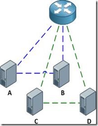
With the configurations above applied, the router is able to communicate with all hosts, and all hosts are able to communicate with the router and with the other host in their respective community private VLANs (e.g. host A can reach the router and host B, but not host C or D).

clip_image004

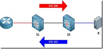
Of course, good network engineers aren't satisfied simply knowing that something works: we want to know how it works. This functionality is actually achieved by bending some rules about VLAN assignments. Traditionally, you expect return traffic originating within a VLAN to come back over the trunk tagged with that same VLAN ID. This is not always the case with private VLANs.

When the router sends a frame to one of the hosts on S2, the frame is tagged as belonging to the primary VLAN 100 when it traverses the trunk, because the router is attached to a promiscuous port. Frames originating from the hosts, however, are tagged with their appropriate secondary VLAN IDs. A frame from host B back to the router, for example, is tagged as VLAN 101 when traversing the trunk link.

clip_image006

To summarize:

· Frames originating from a promiscuous port are tagged with the primary VLAN ID

· Frames originating from a host port are tagged with the secondary (isolated or community) VLAN ID

And of course, here's a packet capture to help drive the idea home.

SVIs

What if we wanted to remove the router from our topology and do all inter-VLAN routing locally on our multilayer switch S1? No problem, we just need to create the primary VLAN SVI (switched virtual interface, also commonly referred to as a VLAN interface) and apply to it a mapping for our secondary VLANs. First we'll shut down the interface connected to the router and enable multilayer switching.

S1(config)# interface f0/1

S1(config-if)# shutdown

S1(config-if)# exit

S1(config)# ip routing

Next, we'll create the SVI for VLAN 100, assign it the IP address which was previously assigned to the router, and map our secondary VLANs.

S1(config)# interface vlan100

S1(config-if)# ip address 192.168.0.1 255.255.255.0

S1(config-if)# private-vlan mapping 101-102

S1(config-if)#

%PV-6-PV_MSG: Created a private vlan mapping, Primary 100, Secondary 101

%PV-6-PV_MSG: Created a private vlan mapping, Primary 100, Secondary 102

S1 now functions in place of the external router; all hosts can reach its routed Vlan100 interface but are still restricted to communicating with hosts in their secondary VLAN.

clip_image007

About the Author

Jeremy Stretch is a network engineer living in the Raleigh-Durham, North Carolina area. He is known for his blog and cheat sheets here at Packet Life. You can reach him by email or follow him on Twitter.

Taken From: http://packetlife.net/blog/2010/oct/28/private-vlans-trunks-and-svis/

Private VLAN – Basics (Cisco)

Basic Private VLAN Configuration

By stretch | Monday, August 30, 2010 at 12:53 a.m. UTC

Now that the community lab has been equipped with a Catalyst 3560, I have finally been able to write about private VLANs (which are supported only on Catalyst 3560 and higher switches). This article discusses the concept of private VLANs and includes a basic configuration example, with more complex configurations deferred for future articles.

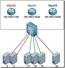
Private VLANs were developed to provide the ability to isolate end hosts at layer two. To understand the motivation behind this feature, consider a colocation environment in which the network operator must connect servers belonging to different customers to the Internet. These servers must all be able to reach their first-hop router, but for security reasons, servers belonging to one customer must not be able to communicate with servers belonging to another. An obvious design solution for these requirements is to place each customer's servers in a separate VLAN, which also requires the assignment of a separate IP subnet per customer (even if they have only one server).

clip_image002

This approach wastes both VLAN IDs and IP address space. Private VLANs were introduced as a more elegant alternative, allowing multiple devices to reside in the same IP subnet, yet remain isolated from one another at layer two.

clip_image004

A private VLAN is defined as a pairing of a primary VLAN with a secondary VLAN. Primary VLANs are the normal VLANs we all know and love. Secondary VLANs use the same VLAN ID range and are defined in the same manner as primary VLANs, but are specially designated to operate as secondary VLANs in one of two modes:

· Isolated - The end points of all ports assigned to an isolated private VLAN cannot communicate with one another, nor with host ports in any other private VLANs.

· Community - End points attached to community ports can communicate with one another, but not with ports in other private VLANs.

An access port assigned to a private VLAN operates in one of two modes:

· Host - The port inherits its behavior from the type of private VLAN it is assigned to.

· Promiscuous - The port can communicate with any other private VLAN port in the same primary VLAN.

Configuring Private VLANs

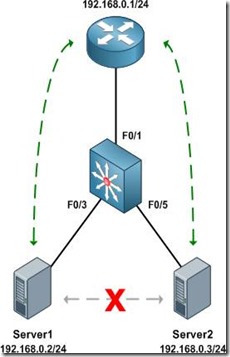
We'll configure an isolated private VLAN to allow two servers owned by different customers in the same IP subnet to communicate with their first-hop router, but not with one another.

clip_image006

Before getting started with private VLAN configuration, ensure that VTP has been set to transparent mode. There are numerous reasons for running VTP in transparent mode beyond the scope of this article, and to enable private VLANs it's explicitly required.

Switch(config)# vtp mode transparent

Setting device to VTP TRANSPARENT mode.

As with normal VLANs, private VLANs must be created before they can be used. Upon creation, we must also define a type (isolated, community, or primary) for each. We'll create our secondary VLANs first, then our primary VLAN. The secondary private VLAN is mapped under the configuration of the primary private VLAN.

Switch(config)# vlan 101

Switch(config-vlan)# private-vlan isolated

Switch(config-vlan)# vlan 100

Switch(config-vlan)# private-vlan primary

Switch(config-vlan)# private-vlan association 101

Our completed VLAN configuration looks like this:

vlan 100

private-vlan primary

private-vlan association 101

!

vlan 101

private-vlan isolated

Next, we designate our private VLAN interfaces. Our uplink port to the router will be set to promiscuous mode, with the primary VLAN mapped to the secondary VLAN.

Switch(config)# interface f0/1

Switch(config-if)# switchport mode private-vlan promiscuous

Switch(config-if)# switchport private-vlan mapping 100 101

Our two server ports will be configured in host mode:

Switch(config)# interface f0/3

Switch(config-if)# switchport mode private-vlan host

Switch(config-if)# switchport private-vlan host-association 100 101

Switch(config-if)# interface f0/5

Switch(config-if)# switchport mode private-vlan host

Switch(config-if)# switchport private-vlan host-association 100 101

At this point our private VLAN configuration is complete. We can verify private VLAN interface assignments with the command show vlan private-vlan:

Switch# show vlan private-vlan

Primary Secondary Type Ports

------- --------- ----------------- ------------------------------------------

100 101 isolated Fa0/1, Fa0/3, Fa0/5

Switch# show interface status

Port Name Status Vlan Duplex Speed Type

Fa0/1 connected 100 a-full a-100 10/100BaseTX

Fa0/2 notconnect 1 auto auto 10/100BaseTX

Fa0/3 connected 100,101 a-full a-100 10/100BaseTX

Fa0/4 notconnect 1 auto auto 10/100BaseTX

Fa0/5 connected 100,101 a-full a-100 10/100BaseTX

Fa0/6 notconnect 1 auto auto 10/100BaseTX

Fa0/7 notconnect 1 auto auto 10/100BaseTX

...

The command show interface switchport is also useful for examining private VLAN details per interface.

Finally, we can verify that the router can communicate with both servers, but the servers cannot communicate directly with one another.

Router# ping 192.168.0.2

Type escape sequence to abort.

Sending 5, 100-byte ICMP Echos to 192.168.0.2, timeout is 2 seconds:

!!!!!

Success rate is 100 percent (5/5), round-trip min/avg/max = 1/2/4 ms

Router# ping 192.168.0.3

Type escape sequence to abort.

Sending 5, 100-byte ICMP Echos to 192.168.0.3, timeout is 2 seconds:

!!!!!

Success rate is 100 percent (5/5), round-trip min/avg/max = 1/1/4 ms

Server1# ping 192.168.0.3

Type escape sequence to abort.

Sending 5, 100-byte ICMP Echos to 192.168.0.3, timeout is 2 seconds:

.....

Success rate is 0 percent (0/5)

Further Reading

· Configuring Private VLANs - Catalyst 3560 configuration guide

· RFC 5517 - Cisco Systems' Private VLANs: Scalable Security in a Multi-Client Environment

clip_image007

About the Author

Jeremy Stretch is a network engineer living in the Raleigh-Durham, North Carolina area. He is known for his blog and cheat sheets here at Packet Life. You can reach him by email or follow him on Twitter.

Taken From: http://packetlife.net/blog/2010/aug/30/basic-private-vlan-configuration/

Thursday, January 2, 2014

Universal Tablet USB Charging Adapter (DIY)

DIY Universal USB Charging Adapter (Step-By-Step w/Pics)


This DIY is based upon work done by ericlmccormick.
*DIY means DIAYOR (Do It At Your Own Risk). I'm not responsible if you break/bend/mutilate/damage/fold/crater/molest/etc. your tablet as a result of following these instructions.


If you're running Pershoot's kernel, you don't need to do this. You can enable Anycharge through the kernel. See here.

Thanks to MRBR7 for testing and confirming this also works for the GTab 7.7 6800gt.

Thanks to m_1000rr6 for testing and confirming this also works for the GTab 8.9 LTE.

Thanks to NRGZ28 for testing and confirming this also works for the Original Verizon GTab 7.


TOOLS
(Left to Right)
- Something to hold the tiny pieces together while you solder
- Wire snips
- Solder
- Pliers
- Soldering Iron

clip_image001

PARTS
(Left to Right)
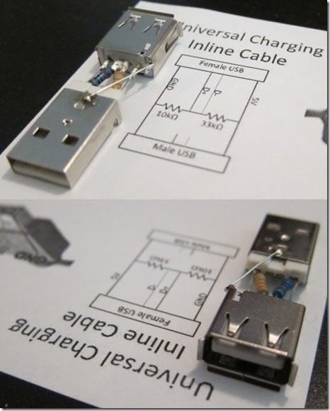
- Male USB Connector
- Female USB Connector
- One 33K Resistor
- One 10k Resistor
clip_image002
I ripped my USB connectors out of a USB extension cable.
clip_image003
Cleaned them up a bit.
clip_image004
IMPORTANT
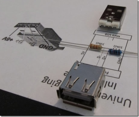
Pay constant attention to the orientation of the USB connectors to each other and which pins are GND and +5V. You could damage your Tab if you end up switching GND and +5V by mistake.You could also end up with a non-working adapter if you flip the resister locations.
clip_image005
clip_image006
clip_image007
STEP 1
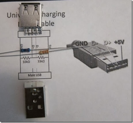
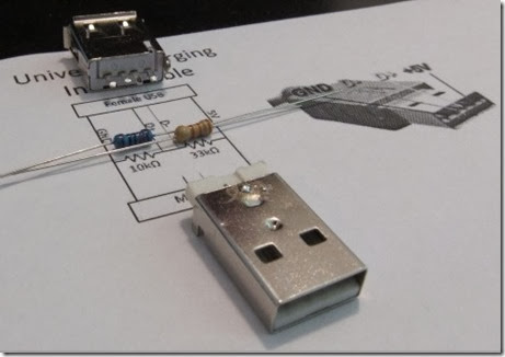
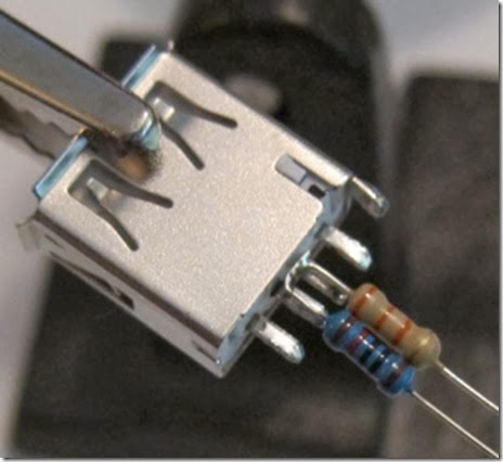
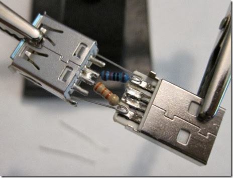
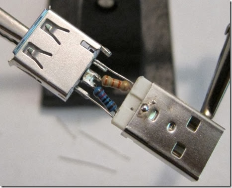
Place the resisters side by side and solder their leads together on one side. Then solder them to the D pins of the female USB connector. Make sure the 10K resistor is on the D pin closest to GND! Keep the trimmed resistor leads for use in Step 4.

clip_image008
STEP 2
Angle the non-soldered ends of the two resistors away from each other so they line up with the GND and +5V pins of the male USB connector. Make sure the USB connectors are aligned so their respective GND and +5V pins are on the same sides! Solder.
clip_image009
STEP 3
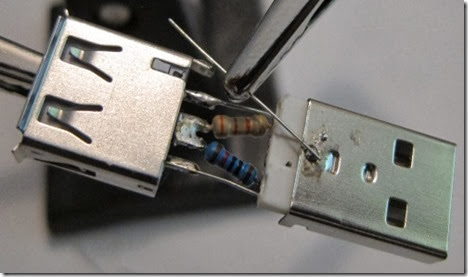
Now clip the resistor leads that were bent back towards the female USB connector and solder them to its GND and +5V pins. Double check that the USB connectors are aligned so their respective GND and +5V pins are on the same sides! BE PARANOID.
clip_image010
STEP 4
Use the trimmed resistor lead you kept from Step 1 to solder the chassis of the USB connectors together.
clip_image011
STEP 5
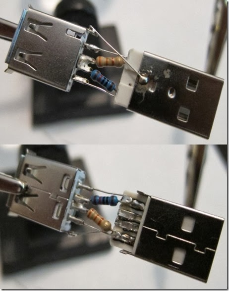
Take 5 minutes to admire your handiwork.
clip_image012
STEP 6 (IMPORTANT - DO NOT SKIP)
Take 10 minutes to check the following
(1) USB connectors are lined up correctly. GND & +5V are not crossed.
(2) 10K resistor comes from GND and 33K resistor comes from +5V. Adapter won't work otherwise.
(3) There are not short circuits / crossed / touching wires. Many bad things could happen.
clip_image013
clip_image014
STEP 7 (TEST)
Without adapter. @$%#!
clip_image015
With adapter. Success!
clip_image016
NEVER CONNECT YOUR TAB TO A USB PORT THAT SUPPLIES MORE THAN 2A - BE PARANOID.
STEP 8
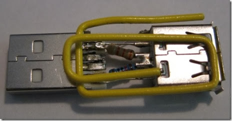
Reinforcing and packaging (paperclips & electrical tape).
clip_image017
clip_image018
clip_image019
STEP 9
Thank me (hit that button over there clip_image021
Hope you found this post useful and informative.

Taken From: http://forum.xda-developers.com/showthread.php?t=1675042

Tuesday, December 10, 2013

How to Setup a USB 3G Modem – Linux / Raspberry Pi

How to setup a USB 3G Modem on Raspberry PI using usb_modeswitch and wvdial

clip_image001 
Setting up a USB 3G/4G modem on a Raspberry Pi is not a simple task. There are many guides available using the now defunctsakis3g script, but getting my modem to work required a bit more understanding.

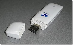
The main problem is that most USB modems act as two devices - a USB storage device and a USB modem. When plugged in to the Raspberry PI the device is usually in USB storage mode. There is a program calledusb_modeswitch that we can use to do the switching

The other missing part is a way to connect to the cellular network with the USB modem from the Raspberry. For this we will use the classic pppand wvdial programs.
Requirements

  • Raspberry PI computer
  • Raspbian OS installed
  • USB 3G Modem
  • 5V 1A power supply for the Raspberry PI
    ________________________________________

1. Install required software

  • Connect your Raspberry PI to the internet via LAN or Wifi
  • Open a terminal window and enter:

sudo apt-get update
sudo apt-get install ppp wvdial
sudo aptitude install usb-modeswitch

2. Get the USB switching codes

  • We need to get the codes of the USB device in USB storage mode and USB modem mode.
  • Connect your USB modem and reboot the Raspberry PI without LAN or Wifi connection
  • Once rebooted open a terminal window and enter:

lsusb

  • The output will look similar to the screenshot below. Your modem should be listed as one of the USB devices. Note the numbers underlined. These are the device vendor and product codes.

clip_image002[5]

  • Make a note of these numbers. In this case it is 19d2:2000
  • This value will later be used in the DefaultProduct value
  • Then we need to soft reboot the Rapberry PI with the modem connected.
  • Open a terminal window and enter:

sudo reboot

  • Once rebooted open a terminal window and enter:

lsusb

  • The output will look similar to the screenshot below. Your modem should be listed and if you are lucky the second set of numbers would have changed. This is usb_modeswitch doing it's job and switching the device to USB modem mode.

clip_image002

  • Make a note of the new numbers. In this case it is 19d2:2002
  • This value will be used later in the TargetProduct value

3. Create custom usb_modeswitch config file

  • We need to create a custom config file for usb_modeswitch on the Raspberry PI because on a cold boot the device is not always active yet when usb_modeswitch runs on startup and the device is left in USB storage mode.
  • We will extract some more information for our usb_modeswitch config file so that we can do the switching manually.
  • Open a terminal window and enter the following replacing the codes 19d2 and 2000 with the codes you noted in step 2. Also note the added backslash.

cd /tmp
tar -xzvf /usr/share/usb_modeswitch/configPack.tar.gz 19d2\:2000

  • Now open the extracted file with a text editor like leafpad replacing the codes noted in step 2.

nano 19d2:2000

  • The content of the file should look something similar to the screenshot below.
  • The parts we are interested in are shown in blue.

clip_image002[7]

  • Now open the /etc/usb_modeswitch.conf file and add the information obtained above to the file.
  • Open a terminal window and enter:

sudo nano /etc/usb_modeswitch.conf

  • Then add the following replacing the codes and MessageContent values with those of your device and save.

DefaultVendor=0x19d2
DefaultProduct=0x2000

TargetVendor=0x19d2
TargetProduct=0x2002

MessageContent="5553424312345678000000000000061e000000000000000000000000000000"
MessageContent2="5553424312345679000000000000061b000000020000000000000000000000"
MessageContent3="55534243123456702000000080000c85010101180101010101000000000000"

4. Create the wvdial config file

  • The next step is to create a config file for wvdial so you can connect to your service provider.
  • Open a terminal window and enter:

sudo nano /etc/wvdial.conf

  • Replace the content of the file with the following.

[Dialer 3gconnect]
Init1 = ATZ
Init2 = ATQ0 V1 E1 S0=0 &C1 &D2 +FCLASS=0
Init3 = AT+CGDCONT=1,"IP","internet"
Stupid Mode = 1
Modem Type = Analog Modem
ISDN = 0
Phone = *99#
Modem = /dev/gsmmodem
Username = { }
Password = { }
Baud = 460800

For the portuguese mobile operators configurations just check: http://myhowtosandprojects.blogspot.pt/2012/04/configuracoes-3g-e-mms-portugal.html 

  • Replace internet with your service provider's APN
  • Replace the Phone number if you need to dial a different code to connect.
  • Replace Username and Password if needed. To leave the username and password as blank use { }

5. Connect to the internet

  • To connect we need to make sure the device is in modem mode.
  • First get the actual modem state (CD-ROM):

lsusb

Bus 001 Device 002: ID 0424:9512 Standard Microsystems Corp.
Bus 001 Device 001: ID 1d6b:0002 Linux Foundation 2.0 root hub
Bus 001 Device 003: ID 0424:ec00 Standard Microsystems Corp.
Bus 001 Device 004: ID 19d2:2000 ZTE WCDMA Technologies MSM MF627/MF628/MF628+/MF636+ HSDPA/HSUPA

  • Open a terminal and enter:

sudo usb_modeswitch -c /etc/usb_modeswitch.conf

to change the from the CD-ROM mode to the modem mode

Now check that the mode switch occured:

lsusb

Bus 001 Device 002: ID 0424:9512 Standard Microsystems Corp.
Bus 001 Device 001: ID 1d6b:0002 Linux Foundation 2.0 root hub
Bus 001 Device 003: ID 0424:ec00 Standard Microsystems Corp.
Bus 001 Device 005: ID 19d2:0031 ZTE WCDMA Technologies MSM MF110/MF627/MF636

  • Then connect to the internet with:

wvdial 3gconnect

6. Problems

If you have problems with the “wvdial”, you shoul run

wvdialconf

this will scan your system for modems, if it finds one, it will do some tests to determine your modem’s parameters, and write them to a template config in /etc/wvdial.conf :

Editing `/etc/wvdial.conf'.

Scanning your serial ports for a modem.

ttyUSB0<*1>: ATQ0 V1 E1 -- failed with 2400 baud, next try: 9600 baud
ttyUSB0<*1>: ATQ0 V1 E1 -- failed with 9600 baud, next try: 9600 baud
ttyUSB0<*1>: ATQ0 V1 E1 -- and failed too at 115200, giving up.
ttyUSB1<*1>: ATQ0 V1 E1 -- OK
ttyUSB1<*1>: ATQ0 V1 E1 Z -- OK
ttyUSB1<*1>: ATQ0 V1 E1 S0=0 -- ERROR
ttyUSB1<*1>: ATQ0 V1 E1 &C1 -- ERROR
ttyUSB1<*1>: ATQ0 V1 E1 &D2 -- ERROR
ttyUSB1<*1>: ATQ0 V1 E1 +FCLASS=0 -- OK
ttyUSB1<*1>: Modem Identifier: ATI -- Manufacturer: ZTE INCORPORATED
ttyUSB1<*1>: Speed 9600: AT -- OK
ttyUSB1<*1>: Max speed is 9600; that should be safe.
ttyUSB1<*1>: ATQ0 V1 E1 +FCLASS=0 -- OK
ttyUSB2<*1>: ATQ0 V1 E1 -- OK
ttyUSB2<*1>: ATQ0 V1 E1 Z -- OK
ttyUSB2<*1>: ATQ0 V1 E1 S0=0 -- ERROR
ttyUSB2<*1>: ATQ0 V1 E1 &C1 -- ERROR
ttyUSB2<*1>: ATQ0 V1 E1 &D2 -- ERROR
ttyUSB2<*1>: ATQ0 V1 E1 +FCLASS=0 -- OK
ttyUSB2<*1>: Modem Identifier: ATI -- Manufacturer: ZTE INCORPORATED
ttyUSB2<*1>: Speed 9600: AT -- OK
ttyUSB2<*1>: Max speed is 9600; that should be safe.
ttyUSB2<*1>: ATQ0 V1 E1 +FCLASS=0 -- OK

Found a modem on /dev/ttyUSB1.
Modem configuration written to /etc/wvdial.conf.

ttyUSB1<Info>: Speed 9600; init "ATQ0 V1 E1 +FCLASS=0"
ttyUSB2<Info>: Speed 9600; init "ATQ0 V1 E1 +FCLASS=0"

You config template should look something like this:

[Dialer Defaults]
Init1 = ATZ
Init2 = ATQ0 V1 E1 +FCLASS=0
Modem Type = Analog Modem
; Phone = <Target Phone Number>
ISDN = 0
; Password = <Your Password>
; Username = <Your Login Name>
Modem = /dev/ttyUSB1
Baud = 9600

go to step 4 and change:

[Dialer 3gconnect]
Init1 = ATZ

Init2 = ATQ0 V1 E1 +FCLASS=0
Init3 = AT+CGDCONT=1,"ip","internet"
Stupid Mode = 1
Modem Type = Analog Modem
ISDN = 0
Phone = *99#
Modem = /dev/ttyUSB1
Username = tmn
Password = tmn
Baud =
9600

and then try again:

wvdial 3gconnect

Base on: http://www.thefanclub.co.za/how-to/how-setup-usb-3g-modem-raspberry-pi-using-usbmodeswitch-and-wvdial

Related Info:

Sunday, December 8, 2013

Setting up Wifi via the Command Line – Linux/Raspberry Pi (WPA2)

image

The Raspberry Pi has many great features straight out of the box,  unfortunately WiFi is not one of them, in this guide I’ll show you how I WiFi equipped my Raspberry PI for only a fiver.
We will be assuming that you have a head less setup (without a monitor) so the guide should work for everyone, either via SSH (remote) or via a local terminal session if you do have a monitor.
Also its worth noting that some WiFi adapters will require a powered USB hub between the Raspberry PI and the USB module, the one used below doesn’t due to it’s power consumption assuming you don’t have anything else drawing large currents from the USB power.

1. What you will need…

  • Raspberry Pi, with Wheezy
  • Internet Connection (via the ethernet port to begin with)
  • WiFi network to test on image
  • USB WiFi Dongle, either of the below work:
  • Amazon Link (USA Amazon)
  • Amazon Link or Amazon Link (UK Amazon)


2. Update the OS

There are so many times you will run into a bug when installing something new and find out that it would have worked if your system was up to date, taking no risks here so get your system updated

sudo apt-get update
sudo apt-get upgrade

Due to the RAM/CPU power on the Pi’s, this might take a while, brew anyone? 
  
 
3. Reboot

Power down the device, install your WiFi USB module and turn it back on.


4. Setup the interface configuration

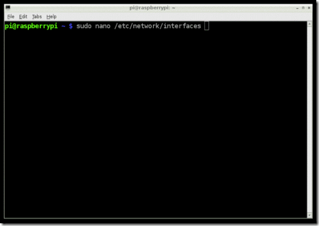
sudo nano /etc/network/interfaces

Normally your base configuration will look something like this?

  allow-hotplug wlan0
 
  iface wlan0 inet manual
  wpa-roam /etc/wpa_supplicant/wpa_supplicant.conf

  iface default inet dhcp

Assuming you have a DHCP server on your LAN (normally your DSL/Cable router) use the following configuration, your SSID and password will be put in the wpa_supplicant.conf later on in this guide.

## FILE: /etc/network/interfaces ##
  allow-hotplug wlan0
 
  iface wlan0 inet manual
  wpa-roam /etc/wpa_supplicant/wpa_supplicant.conf

  iface wlan0 inet dhcp

If you don’t have a DHCP server, or if you want to just statically assign the IP address you can use the following, however update the IP, Netmask and Gateway to match your network.

## FILE: /etc/network/interfaces ##
  allow-hotplug wlan0
 
  iface wlan0 inet manual                           
  wpa-roam /etc/wpa_supplicant/wpa_supplicant.conf
   
  iface wlan0 inet static
  network 192.168.1.0
  address 192.168.1.249
  netmask 255.255.255.0
  gateway 192.168.1.254
  broadcast 192.168.1.255
 

5. Setup the WPA configuration

Finally you will want to edit the WPA configuration as below, don’t forget to update it for your SSID and WPA password!

## FILE: /etc/wpa_supplicant/wpa_supplicant.conf ##
  network={
  ssid="SSID-GOES-HERE"
  proto=RSN
  key_mgmt=WPA-PSK
  pairwise=CCMP TKIP
  group=CCMP TKIP
  psk="WIFI-PASSWORD-GOES-HERE"
  }

6. Final Reboot

Ok that should be it, do a final reboot remove the wired ethernet cable and your IP should automatically come onto the network as a normal WiFi device.

OR do the the following if you don’t want to reboot:

sudo ifdown wlan0
sudo ifup wlan0
   

Problems?

First

This device should work out of the box, if for any reason it doesn’t you will want to do the following:

sudo wget http://dl.dropbox.com/u/80256631/install-rtl8188cus-latest.sh -O /boot/install-rtl8188cus-latest.sh

sudo /boot/install-rtl8188cus-latest.sh

Now go back to step 3 and try again.


Second

Run the below command, you should see your WiFi device there? If not there could be an issue with the hardware, try it in another PC…

lsusb

You should see a line that looks like this:

Bus 001 Device 005: ID 0bda:8189 Realtek Semiconductor Corp. RTL8187B Wireless 802.11g Network adapter.

Based On: http://pingbin.com/2012/12/setup-wifi-raspberry-pi/


About WPA2 (aka IEEE 802.11i-2004) & WPA SUPLICANT

Short for Wi-Fi Protected Access 2, the follow on security method to WPA for wireless networks that provides stronger data protection and network access control.

It provides enterprise and consumer Wi-Fi users with a high level of assurance that only authorized users can access their wireless networks.

Based on the IEEE 802.11i standard, WPA2 provides government grade security by implementing the National Institute of Standards and Technology (NIST) FIPS 140-2 compliant AES encryption algorithm and 802.1x-based authentication.  [Adapted from Wi-Fi.org]

There are two versions of WPA2:

  • WPA2-Personal (password)
  • WPA2-Enterprise (server authentication)

WPA2-Personal protects unauthorized network access by utilizing a set-up password. WPA2-Enterprise verifies network users through a server. WPA2 is backward compatible with WPA.

LINKS

Saturday, December 7, 2013

Setting up Wifi via the Command Line – Linux/Raspberry Pi (WPA aka WPA1)

Setting up Wifi with the Command Line

Created by Simon Monk

This tutorial works best if your router is broadcasting the SSID. Make sure you have "Broadcast SSID" set up on your router! This may not work with "private" SSID setups

Setting up WiFi in Occidentalis, is also pretty straight forward. You just need to add the name of your wireless network (its SSID) and your password to a configuration file.

Step 1.

Boot the Raspberry Pi without the WiFi adapter plugged in.

Step 2.

Open a Terminal session by clicking on the LXTerminal icon, and enter the following command into it:

Copy Code

1. sudo nano /etc/network/interfaces

clip_image002

    auto lo

    iface lo inet loopback
    iface eth0 inet dhcp

    allow-hotplug wlan0
    auto wlan0

    iface wlan0 inet dhcp
    wpa-ssid "ssid"
    wpa-psk "password"

If you are using a 'hidden' SSID, try the following (hat-tip to http://www.dafinga.net/2013/01/how-to-setup-raspberry-pi-with-hidden.html)

    auto lo

    iface lo inet loopback
    iface eth0 inet dhcp

    auto wlan0
    allow-hotplug wlan0
    iface wlan0 inet dhcp
    wpa-scan-ssid 1
    wpa-ap-scan 1
    wpa-key-mgmt WPA-PSK
    wpa-proto RSN WPA
    wpa-pairwise CCMP TKIP
    wpa-group CCMP TKIP
    wpa-ssid "My Secret SSID"
    wpa-psk "My SSID PSK"

    iface default inet dhcp

Step 3.

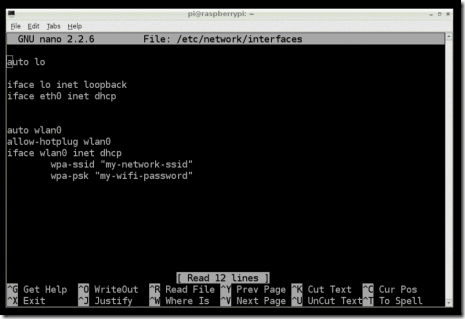
This opens an editor screen of the wifi configuration file you need to change.

clip_image004

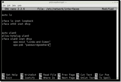
The two places where you need to make a change are on the last two lines. Change the file so that it looks like this:

clip_image006

Of course, you should put in your network and password! Note that you need to keep the double-quote characters around your wireless network name and password.

This kind of editor does not let you use the mouse. Instead, use the cursor keys to move around the file.

Step 4.

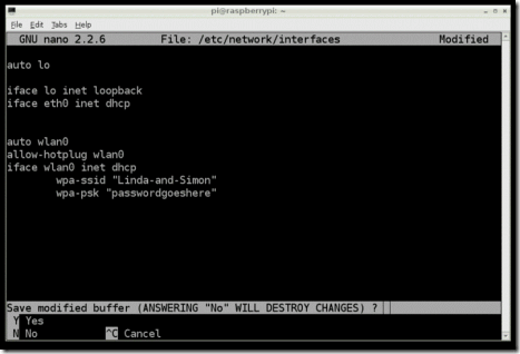
When you have finished press [ctrl]x. This will ask if you want to save the modified files.

clip_image008

Press 'Y' and then Return to save the file with the same name.

Step 5.

Shut down your Raspberry Pi, plug the WiFi adapter in and start it up again. You should find that the Raspberry Pi connects using the WiFi adapter as it boots up.

Taken From: http://learn.adafruit.com/adafruits-raspberry-pi-lesson-3-network-setup/setting-up-wifi-with-occidentalis