Thursday, April 30, 2015

Windows 8.x as an Wifi Access Point

CONFIGURE WINDOWS 8 & 8.1 TO PROVIDE SECURE WIRELESS ACCESS POINT SERVICES TO WI-FI CLIENTS - TURN WINDOWS 8 INTO AN ACCESS POINT

POSTED IN WINDOWS 8 & WINDOWS 8.1

Windows 8 and Windows 8.1 (including Professional edition) operating systems provide the ability to turn your workstation or laptop into a secure wireless access point, allowing wireless clients (including mobile devices) to connect to the local network or Internet. This feature can save you time, money and frustration when there is need to connect wireless devices to the network or Internet but there is no access point available.

In addition, using the method described below, you can turn your Windows system into a portable 3G router by connecting your workstation to your 3G provider (using your USB HSUPA/GPRS stick).

Windows 7 users can visit our article Configuring Windows 7 To Provide Secure Wireless Access Point Services to Wi-Fi Clients - Turn Windows into an Access Point

To begin, open your Network Connections window by pressing Windows Key + R combination to bring up the Run window, and typencpa.cpl and click OK:

clip_image002

Figure 1. Run Command – Network Connections

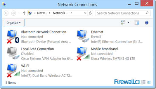
The Network Connection window will appear, displaying all network adapters the system current has installed:

clip_image003

Figure 2. Network Connections

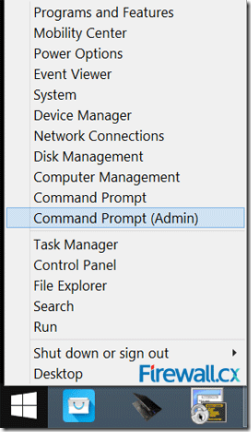
Let’s now create our new wireless virtual adapter that will be used as an access point for our wireless clients. To do this, open anelevated Command prompt (cmd) by right-clicking on the Window 8 start button located on the lower left corner of the desktop and select Command Prompt (Admin). If prompted by the User Account Control protection, simply click on Yes to proceed:

clip_image004

Figure 3. Opening an elevated Command Prompt

Once the command prompt is open, enter the following command to create the wireless network (SSID). The encryption used by default is WPA2-PSK/AES:

C:\windows\system32> netsh wlan set hostednetwork mode=allow ssid=Firewall.cx key=$connect$here

When the command is entered, the system will return the following information:

The hosted network mode has been set to allow.
The SSID of the hosted network has been successfully changed. 
The user key passphrase of the hosted network has been successfully changed.

In our example, the Wi-Fi (SSID) is named Firewall.cx and has a password of $connect$here.

The system information above confirms the creation of the wireless network and creates our virtual adapter which will be visible in theNetwork Connection window after the virtual adapter is enabled with the following command:

C:\windows\system32> netsh wlan start hostednetwork

Again, the system will confirm the wireless network has started with the below message:

The hosted network started.

Looking at the Network Connection window we’ll find our new adapter labeled as Local Area Connection 4. Right under the adapter is the SSID name of the wireless network created by the previous command:

clip_image005

Figure 4. Network Connections – Our new adapter appears

At this point, our new wireless network (Firewall.cx) should be visible to all nearby wireless clients.

Next, we need to enable Internet sharing on the network adapter that has Internet access. In our case this is the Ethernet adapter. Users accessing the Internet via their mobile broadband adapter should select their broadband adapter instead.

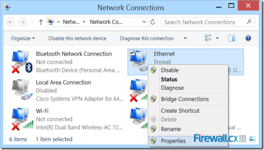
To enable Internet sharing, right-click on the Ethernet network adapter and select properties from the context menu, as shown below:

clip_image006

Figure 5. Network Connections – Ethernet Adapter Properties

Once the Ethernet adapter properties window appears, select the Sharing tab and tick the Allow other network users to connect through this computer’s Internet connection then select the newly created virtual adapter labelled Local Area Connection 4:

clip_image007

Figure 6. Enabling sharing and selecting the newly created virtual adapter

Be sure to untick the second option below (not clearly visible in above screenshot): Allow other network users to control or disable the shared Internet connection, then click on OK.

Notice our Ethernet adapter now has the word Shared in its description field:

clip_image008

Figure 7. Our Ethernet adapter now appears to be shared

At this point, clients that have successfully connected to our wireless SSID Firewall.cx should have Internet access.

Note that in some cases, it might be required to perform a quick restart of the operating system before wireless clients have Internet access. Remember that in case of a system restart, it is necessary to enter all command prompt commands again.

The command below will help verify the wireless clients connected to our Windows 8 access point:

C:\windows\system32> netsh wlan show hostednetwork

clip_image009

Figure 8. Information on our Windows 8 access point

As shown above, we have one wireless client connected to our Windows 8 access point. Windows 8 will support up to 100 wireless clients, even though that number is extremely likely to ever be reached.

This article showed how to turn your Windows 8 & Windows 8.1 operating system into a wireless access point, allowing wireless clients to connect to the Internet or Local LAN.

Taken From: http://www.firewall.cx/microsoft-knowledgebase/windows-8/1087-windows-8-secure-access-point.html

 

Friday, April 3, 2015

Arduino – EPLUG: Ethernet Controlled Power Plug

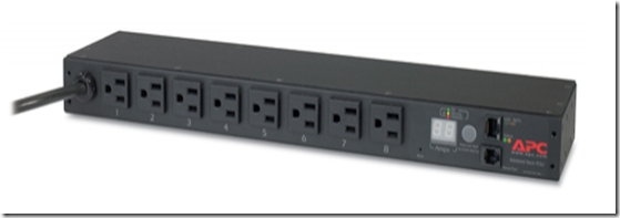
When I started  preparing for my CCNP SWITCH exam I bought some switches and set them up in my basement. After a couple of labs I realized I did a lot of trips to the basement to start / stop / restart the equipments. That’s when I started searching for remote controlled PDU, like this:

image

these are great but are very expensive for personal use (normally used in datacenters).

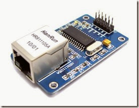
I already had an Arduino, so I started searching for a relay and cheap Ethernet NIC (the one on the arduino store was way to expensive), and I found the components below.

I put the components together and started programing the EPLUG program.

EPLUG is basically a small telnet Command Line Interface (CLI) that you can use to control multiple relays atached to Power Plugs. With this you can turn ON and OFF just about any electronic appliance you own from any device with telnet (PC, SmartPhone, Tablet, etc), using your Home Network or the Internet.
 
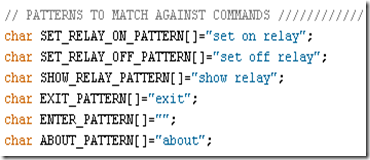
EPLUG was built as a framework that can be used for other projects. You can easily change the commands syntax by changing the text on the command patterns and add new commands by adding a new "else if(..){...}" statements on the "loop()" function.


Components

Relay Model: SRD-05VDC-SL-C

clip_image002

This relay board uses opto-couplers / opto-isolators to drive the relays, these isolate your Arduino from the relays, protecting it from voltage spikes. For more information check these videos:

Ethernet NIC Model: HR911105A

Shield Version

image

Breakout Board Version

ENC28J60_1

when i bought these components i did some basic tutorials on wich we are going to build upon, so you should check them out for more details or to test each component individually:


EPLUG Prototype

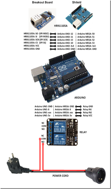
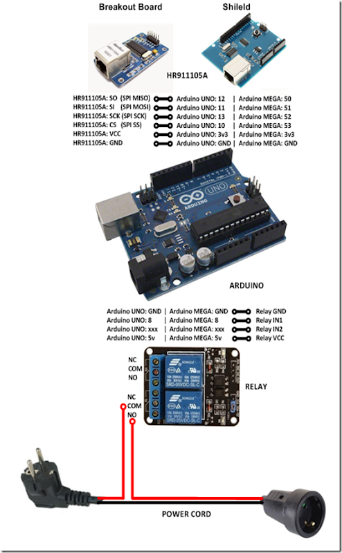
The complete build looks like this:

2015.04.04_Diagrama_Final

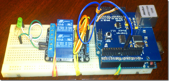
for the prototype I replaced the POWER CORD with an LED for testing:

image

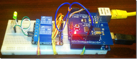
my prototype looked like this:

image

The next step is to add the IP stack (uIP) for the Ethernet NIC (HR911105A).

You basically download the uIP IP stack here:

extract it, and put it on the arduino libraries folder

image


EPLUG as a Framework

The EPLUG program a simple and flexible Command Line Interface (CLI):

image

it receives the command on the function:

  • rcv_cmd(cmd, cmd_len)

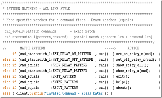
 and matches them against the predefined patterns:

image

using the following functions:

  • cmd_equals (pattern,command) - exact match
  • cmd_startswith_l (pattern,command) - partial match, allow the commands to have a option (in this case the pin number)

and when it finds a match it executes an the function/actions for the corresponding command, as you can see below:

image

the structure above makes EPLUG very flexible, so that it’s easy to:

  • Change the current commands text
  • Add more commands (just add an else if (..){...} line)

my goal was to build EPLUG as a Framework for future projects.

For example if you want to do a program to set LEDs ON/OFF LEDs, you just need to change the patterns and the action functions and in 10 minutes or less your program is done.


Available Pins for Relays

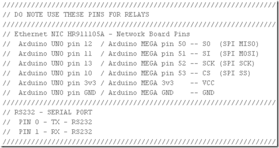
There are some pins that that you should not use:

image

so you should only use the following pins:

  • Pin 2
  • Pin 3
  • Pin 4
  • Pin 5
  • Pin 6
  • Pin 7
  • Pin 8 I used this PIN
  • Pin 9

you can basically plug up to 8 relays to an Arduino UNO and controll them with the EPLUG program.


Loading EPLUG

Get the EPLUG code here:

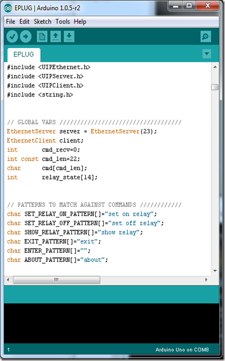
Open the EPLUG code on the Arduino IDE:

image

To upload the program to Arduino just press:

image

after compiling and uploading the IDE show the program size, and it should be 25.xxx bytes.

Problem: I found out that, for some reason, if the program is a bit over 26.000 bytes the Ethernet NIC doesn’t work properly. The maximum on the Arduino UNO is 32.256 bytes so this shouldn`t happen.


Testing EPLUG

First you need to find the IP of the Arduino NIC and make sure it’s on the correct network (your LAN network), you can do that here:

image

now telnet to it:

image

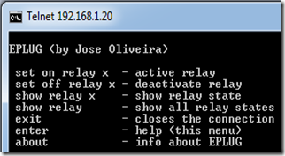
press ENTER to start the CLI and show the options:

image

to set the “relay” (for now the LED) on you type:

image

you should get something like this:

Prototype1

Problem: After some time (1-3 min) the LED goes off for no aparent reason. After some research I found that this behavior is the the Arduino’s In System Programer (ISP) checking  if you want to reprogram Arduino from your PC (basically resets Arduino). The solution is very simple, you just don’t power the Arduino from your PC, you use a power supply.

to show the “relay” (LED) current state, you type:

image

to show all the “relays” (LEDs) current state, you type:

image

to set off the “relay” (LED), you type:

image

to show info about EPLUG, you type:

image

to close the telnet session, you type:

image


Putting It All Together

Now we can replace the LED with the POWER CORD, and use/test EPLUG in the real world.

2015.04.04_Diagrama_Final

In this diagram the POWER CORD starts OFF, if you want it to start ON just change the wire on the relay from NO (normally open) to NC (normally closed).

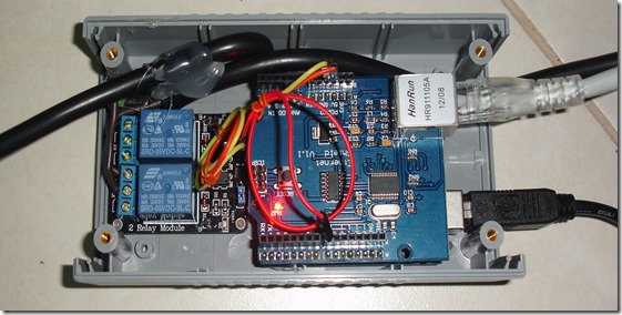
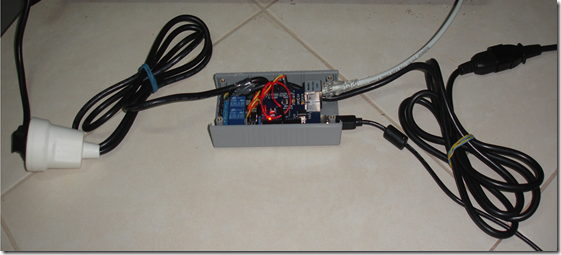
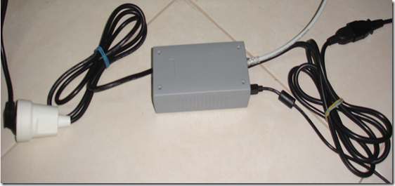
My build looked like this:

REAL1

image

image

now you can test/use it in the real world, check out my test video:

EPLUG Test

Next Steps

  • Add an internal USB power supply
  • Make it a lot smaller/cheaper (microntroller + breakout board)
  • Make a version with GSM aka GPLUG (SMS or GPRS)
  • Make a version with Radio modules aka RPLUG
  • Map relays to numbers different from the PINs
  • Save the pins state to a non-volatile memory (EEPROM)
  • Add a current sensor

Check out my makers community at: