DISCLAIMER: The information provided herein is for general informational and educational purposes only.
Do you have a Mac? Do you have VMware Fusion 6 Professional and GNS3 (with TunTap) installed? Are you ready to implement a multivendor OSPF lab? This post is a culmination of my previous GNS3 posts where we take most of that information to actualize a practical solution.
The lab contains several virtual devices that consume a significant amount of hardware resources. I recommend your Mac computer have a minimum 8GB of memory, and I also recommend a quad-core CPU because the ASAVM device will absorb the full usage of a single core by default. A dual-core CPU will suffice but expect less "headroom".
Core components required for this tutorial:
The following table maps each device to its GNS3 object, hypervisor, and software relationship:
The R1 device can be any GNS3-compatible Cisco IOS router image that supports the OSPF protocol. The software (for the virtual devices) can be downloaded from their respective websites.
1. GNS3 Topology
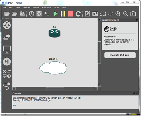
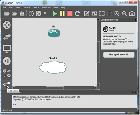
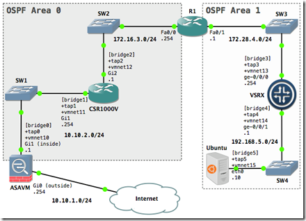
Create a new GNS3 project. Drag and drop the GNS3 objects onto the blank workspace. Arrange them so it looks similar to the layout of the network diagram. The network diagram is the reference point for this tutorial.
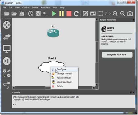
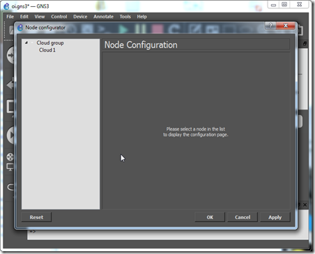
1.1 Configure the GNS3 Host object attributes (right-click or control-click)
For example, if you were starting with the bottom left GNS3 Host object:
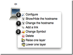
1. Change the hostname from C1 to ASAVM.
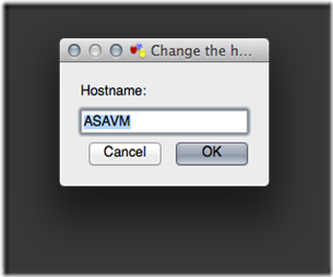
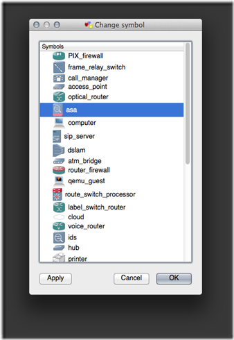
2. Change the object symbol.
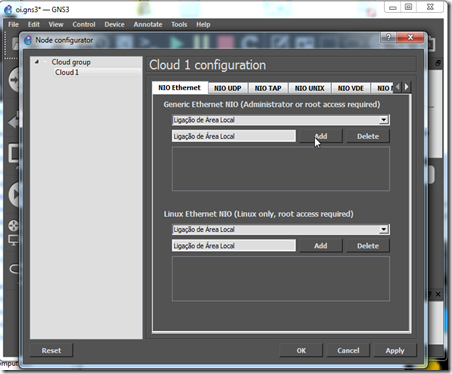
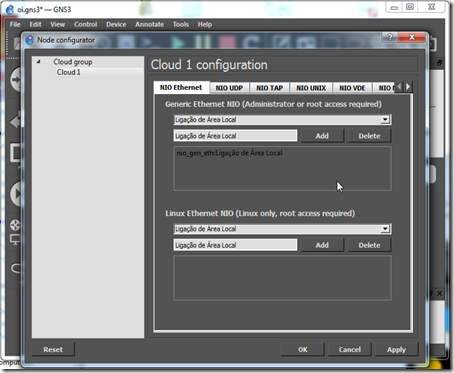
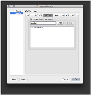
3. Bind the TAP virtual network device(s) to the GNS3 Host object.
Repeat the previous steps for each of the remaining GNS3 Host objects by matching the specific object attributes with the network diagram.
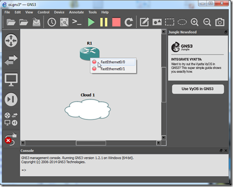
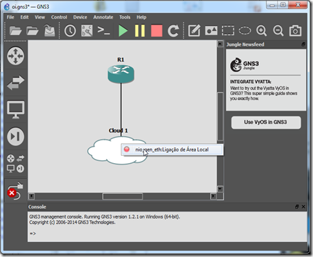
1.2 Add a link between each of the devices
The GNS3 Host objects will be using their specific TAP interface(s) to connect to the Ethernet switches. In an upcoming section, you will understand why the TAP interface is such a vital component for GNS3 and VMware Fusion integration.
We can verify all six TAP interfaces are available by running the following command from the terminal:
$ for i in {0..5}; do ifconfig tap$i; done
2. VMware Fusion
The R1 device and the Ethernet switches are ready, from the perspective of GNS3 (Dynamips) connectivity, so we will zero in on creating the VMware virtual machines and their associated vmnets.
2.1 Virtual Network Switches
Our lab configuration will use host-only network switches. A host-only network (switch) is a network that is completely contained within the host computer. Host-only networking provides a network connection between the virtual machine and the host system by using a virtual network adapter that is visible on the host operating system. As the network diagram shows, we will be usingvmnet10 thru vmnet15.
Add a virtual switch with the following steps:
1. Open the Preferences window for VMware Fusion Professional.
2. Select the Network tab.
3. Click the + symbol to add a new virtual switch. As the following screenshot shows, we will leave the Allow virtual machines on this network to connect to external networks (using NAT) and Provide addresses on this network via DHCPoptions unchecked to create the host-only virtual switch (vmnet).
4. Click the Apply button to save the setting.
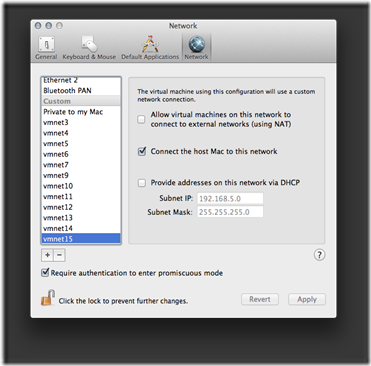
Close the Preferences window when you're finished creating the virtual switches.
We can verify the virtual switches have been created by running this command from the terminal:
$ for i in {10..15}; do ifconfig vmnet$i; done
2.2 Juniper Networks VSRX (Firefly Perimeter)
Import the VMware virtual appliance with the following steps:
1. Click File -> Import... from the VMware Fusion menu bar.
2. Click the Choose File... button.
3. Navigate to and select the junos-vsrx-12.1X46-D10.2-domestic.ova file.
4. Click the Open button.
5. Click the Continue button.
6. Rename the package to VSRX.
7. Click the Save button to save the virtual machine in the default Virtual Machines folder.
8. Click the Accept button for the license agreement.
9. Click the Customize Settings button to change the network configuration.
By default, both the virtual network adapters are configured for Bridged Networking. We need to change them to use the virtual switches we created earlier.
1. Click the Network Adapter menu item.
2. Click the vmnet13 radio button.
3. Click the Show All button to return to the virtual machine settings menu.
4. Click the Network Adapter 2 menu item.
5. Click the vmnet14 radio button.
6. Click the Show All button to return to the virtual machine settings menu.
7. Close the settings window.
Directly edit the VSRX.vmx (virtual machine configuration) file to add the custom virtual serial port. My VSRX virtual machine is located in the default VMware Fusion folder (directory), so I would edit the file with the following command from the terminal:
$ nano $HOME/Documents/Virtual\ Machines.localized/VSRX.vmwarevm/VSRX.vmx
The virtual serial port has to be created for console port access. This is very similar to how we interface with our virtual routers in GNS3 (Dynamips). Add the following statements to the end of the VSRX.vmx file to create a virtual serial port that will allow us to emulate a console port connection via telnet:
serial0.present = "TRUE"
serial0.yieldOnMsrRead = "TRUE"
serial0.fileType = "network"
serial0.fileName = "telnet://127.0.0.1:52151"
We are finished configuring the .vmx file, so let's save (control + o) the file, press the enter key to confirm, then exit (control + x) the nano text editor.
Run the following command to verify the configuration from the terminal:
$ grep serial $HOME/Documents/Virtual\ Machines.localized/VSRX.vmwarevm/VSRX.vmx
serial0.present = "TRUE"
serial0.yieldOnMsrRead = "TRUE"
serial0.fileType = "network"
serial0.fileName = telnet://127.0.0.1:52151
2.3 Cisco CSR1000V
The Open Virtual Appliance (OVA) import process and network configuration is essentially the same as the VSRX.
Import the VMware virtual appliance with the following steps:
1. Click File -> Import... from the VMware Fusion menu bar.
2. Click the Choose File... button.
3. Navigate to and select the csr1000v-universalk9.03.11.00.S.154-1.S-std-C1-M2560-N3-DS8.ova file.
4. Click the Open button.
5. Click the Continue button.
6. Rename the package to CSR1000V.
7. Click the Save button to save the virtual machine in the default Virtual Machines folder.
8. Click the Customize Settings button to change the network configuration.
By default, all three of the virtual network adapters are configured for Bridged Networking. We need to change them to use the virtual switches we created earlier. We will only use the first two network adapters in our topology. Network Adapter 3 can be attached to the default host-only network (Private to my Mac).
1. Click the Network Adapter menu item.
2. Click the vmnet11 radio button.
3. Click the Show All button to return to the virtual machine settings menu.
4. Click the Network Adapter 2 menu item.
5. Click the vmnet12 radio button.
6. Click the Show All button to return to the virtual machine settings menu.
7. Click the Network Adapter 3 menu item.
8. Click the Private to my Mac radio button.
9. Click the Show All button to return to the virtual machine settings menu.
10. Close the settings window.
Just like for the VSRX, directly edit the CSR1000V.vmx (virtual machine configuration) file to add the custom virtual serial port. My CSR1000V virtual machine is located in the default VMware Fusion folder (directory), so I would edit the file with the following command from the terminal:
$ nano $HOME/Documents/Virtual\ Machines.localized/CSR1000V.vmwarevm/CSR1000V.vmx
Add the following statements to the end of the CSR1000V.vmx file to create a virtual serial port that will allow us to emulate a console port connection via telnet:
serial0.present = "TRUE"
serial0.yieldOnMsrRead = "TRUE"
serial0.fileType = "network"
serial0.fileName = "telnet://127.0.0.1:52152"
We are finished configuring the .vmx file, so let's save (control + o) the file, press the enter key to confirm, then exit (control + x) the nano text editor.
Run the following command to verify the configuration from the terminal:
$ grep serial $HOME/Documents/Virtual\ Machines.localized/CSR1000V.vmwarevm/CSR1000V.vmx
serial0.present = "TRUE"
serial0.yieldOnMsrRead = "TRUE"
serial0.fileType = "network"
serial0.fileName = telnet://127.0.0.1:52152
2.4 Cisco Adaptive Security Appliance (ASA)
Refer to my previous post on how to create a Cisco ASA virtual machine in VMware Fusion. For our topology, the outside logical interface will be Network Adapter, and the inside logical interface will be Network Adapter 2 (attached to vmnet10). The outsidelogical interface will be using Bridged Networking because it's the interface that connects our virtual network to the physical world. For my setup, Ethernet 1 is the wired Ethernet network interface on my Mac that has access to the Internet.
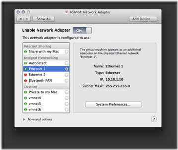
Important: Quit (and reopen) the VMware Fusion application for the .vmx file changes to take effect.
3. Basic Device Configuration
With the GNS3 and VMware sections complete, it's time to focus on each device configuration. I will start with the innermost network device and verify adjacent connections along the path to the ASAVM.
3.1 VSRX
The SRX is typically deployed as a network security device, but it will perform solely as a router in our lab. It runs Junos, so it has the potential to function with practically any network role we would need.
Start VSRX in VMware Fusion, and establish a console port connection to the VSRX device via telnet. Run this command from a new terminal window (tab):
$ telnet 127.0.0.1 52151
Log in as root with no password.
Amnesiac (ttyd0)
login: root
Start the CLI.
root@% cli
Show version information.
root> show version
Model: firefly-perimeter
JUNOS Software Release [12.1X46-D10.2]
Enter configuration mode.
root> configure
Set the root authentication password with a cleartext password.
[edit]
root# set system root-authentication plain-text-password
New password: Pa$$worD1
Retype new password: Pa$$worD1
Set the hostname.
[edit]
root# set system host-name vsrx
Configure the network interfaces.
[edit]
root# set int ge-0/0/0.0 family inet addr 172.28.4.254/24
[edit]
root# set int ge-0/0/1.0 family inet addr 192.168.5.1/24
Remove the ge-0/0/0 interface from the untrust security zone. ge-0/0/0 is a management interface by default, but it will be used as a traffic interface in our topology.
root# delete security zones security-zone untrust interfaces ge-0/0/0.0
Assign the interfaces to the trust security zone.
root# edit security zones security-zone trust
[edit security zones security-zone trust]
root# set interfaces ge-0/0/0
[edit security zones security-zone trust]
root# set interfaces ge-0/0/1
Configure the trust zone to support inbound traffic for the ping system service.
[edit security zones security-zone trust]
root# set host-inbound-traffic system-services ping
Check correctness of syntax for current set of changes.
[edit security zones security-zone trust]
root# commit check
configuration check succeeds
Commit current set of changes and quit configuration mode.
[edit security zones security-zone trust]
root# commit and-quit
commit complete
Exiting configuration mode
Verify the IP configuration for the network interfaces.
root@vsrx> show interfaces ge* terse
Interface Admin Link Proto Local Remote
ge-0/0/0 up up
ge-0/0/0.0 up up inet 172.28.4.254/24
ge-0/0/1 up up
ge-0/0/1.0 up up inet 192.168.5.1/24
From the viewpoint of the host operating system, we need to "glue" a couple of network interfaces together to create a compoundinterface. If you remember from our initial GNS3 Host object configuration, we attached two TAP interfaces to the VSRX object; interface tap3 for ge-0/0/0 and tap4 for ge-0/0/1. GNS3 uses a TAP interface to pass network traffic to the host operating system.
What about VMware? Virtual network adapters are attached to a host-only vmnet (virtual switch); one (or more) network adapters for the VM and another for the host operating system.
What we need is a construct to bind a single TAP interface with the VMware virtual network adapter allocated to the host operating system. That construct is a bridge interface. For our purposes, a bridge interface contains both a TAP interface and the VMware virtual network adapter (for the host OS) as members. Essentially, the members of the bridge interface are put into promiscuous mode, so they're able to "see" each other's network traffic.
Clear the IP configuration for the vmnet13 virtual network interface before adding it as a member to the bridge. Run the following commands from a separate terminal window (tab):
$ sudo ifconfig vmnet13 down
$ sudo ifconfig vmnet13 inet delete
Create a bridge interface for ge-0/0/0 with the following commands from the terminal:
$ sudo ifconfig bridge3 create
$ sudo ifconfig bridge3 addm tap3
$ sudo ifconfig bridge3 addm vmnet13
$ sudo ifconfig bridge3 up
Verify the configuration with the following command from the terminal:
$ ifconfig bridge3
bridge3: flags=8863<UP,BROADCAST,SMART,RUNNING,SIMPLEX,MULTICAST> mtu 1500
options=3<RXCSUM,TXCSUM>
ether 02:1f:5b:a3:f3:03
Configuration:
id 0:0:0:0:0:0 priority 0 hellotime 0 fwddelay 0
maxage 0 holdcnt 0 proto stp maxaddr 100 timeout 1200
root id 0:0:0:0:0:0 priority 0 ifcost 0 port 0
ipfilter disabled flags 0x2
member: tap3 flags=3<LEARNING,DISCOVER>
ifmaxaddr 0 port 14 priority 0 path cost 0
member: vmnet13 flags=3<LEARNING,DISCOVER>
ifmaxaddr 0 port 28 priority 0 path cost 0
Address cache:
0:c:29:b4:c9:e4 Vlan1 vmnet13 1196 flags=0<>
c2:0:2c:1c:0:1 Vlan1 tap3 1190 flags=0<>
media: <unknown type>
status: inactive
Clear the IP configuration for the vmnet14 virtual network interface before adding it as a member to the bridge. Run the following commands from the terminal:
$ sudo ifconfig vmnet14 down
$ sudo ifconfig vmnet14 inet delete
And create a bridge interface for ge-0/0/1 with the following commands from the terminal:
$ sudo ifconfig bridge4 create
$ sudo ifconfig bridge4 addm tap4
$ sudo ifconfig bridge4 addm vmnet14
$ sudo ifconfig bridge4 up
3.2 R1
Start R1 in GNS3. Identify the console port number for R1 in the GNS3 management console with the list R1 command.

Establish a console port connection to the R1 device via telnet. Run this command from a new terminal window (tab):
$ telnet 127.0.0.1 2101
Configure the Fast Ethernet interfaces and bring them up.
R1# conf t
R1(config)# int f0/0
R1(config-if)# ip addr 172.16.3.254 255.255.255.0
R1(config-if)# duplex full
R1(config-if)# speed 100
R1(config-if)# no shut
R1(config-if)# int f0/1
R1(config-if)# ip addr 172.28.4.1 255.255.255.0
R1(config-if)# duplex full
R1(config-if)# speed 100
R1(config-if)# no shut
R1(config-if)# end
Save the running configuration to local NVRAM.
R1# copy run start
Verify network connectivity to the ge-0/0/0 interface of VSRX.
R1# ping 172.28.4.254
Type escape sequence to abort.
Sending 5, 100-byte ICMP Echos to 172.28.4.254, timeout is 2 seconds:
.!!!!
Success rate is 80 percent (4/5), round-trip min/avg/max = 8/22/52 ms
Display the ARP cache.
R1# sh arp
Protocol Address Age (min) Hardware Addr Type Interface
Internet 172.16.3.254 - c200.b04b.0000 ARPA FastEthernet0/0
Internet 172.28.4.1 - c200.b04b.0001 ARPA FastEthernet0/1
Internet 172.28.4.254 0 000c.29b4.c9e4 ARPA FastEthernet0/1
3.3 CSR1000V
Start CSR1000V in VMware Fusion. Select CSR 1000V Serial Console at the GRUB menu.
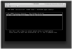
Establish a console port connection to the CSR1000V device via telnet. Run this command from a new terminal window (tab):
$ telnet 127.0.0.1 52152
Enter “no” to bypass the setup command facility.
...
cisco CSR1000V (VXE) processor with 814729K/6147K bytes of memory.
Processor board ID 9LX4G1A6QS5
3 Gigabit Ethernet interfaces
32768K bytes of non-volatile configuration memory.
3145728K bytes of physical memory.
7774207K bytes of virtual hard disk at bootflash:.
--- System Configuration Dialog ---
Would you like to enter the initial configuration dialog? [yes/no]: no
Change the technology package license boot level, and reload for the configuration to take effect.
Router> en
Router# conf t
Router(config)# license boot level premium
Router(config)# end
Router# copy run start
Router# reload
Verify the license.
Router> en
Router# sh license | in Type
License Type: Evaluation
Router# sh license | in Period
Period left: 8 weeks 3 days
Show the current maximum throughput level.
Router# show platform hardware throughput level
The current throughput level is 50000 kb/s
Set the hostname.
Router# conf t
Router(config)# hostname csr1000v
Set lab options.
csr1000v(config)# no ip domain-lookup
csr1000v(config)# line con 0
csr1000v(config-line)# exec-timeout 0 0
csr1000v(config-line)# logging sync
csr1000v(config-line)# end
We can display the interface mapping with the following command:
csr1000v# show platform software vnic-if interface-mapping
-------------------------------------------------------------
Interface Name Driver Name Mac Addr
-------------------------------------------------------------
GigabitEthernet3 vmxnet3 000c.29cb.09b2
GigabitEthernet2 vmxnet3 000c.29cb.09a8
GigabitEthernet1 vmxnet3 000c.29cb.099e
-------------------------------------------------------------
From a separate terminal window (tab), run the following command to verify the CSR1000V virtual machine configuration vNIC order is correct for our topology:
$ grep 00:0c $HOME/Documents/Virtual\ Machines.localized/CSR1000V.vmwarevm/CSR1000V.vmx
ethernet0.generatedAddress = "00:0c:29:cb:09:9e"
ethernet1.generatedAddress = "00:0c:29:cb:09:a8"
ethernet2.generatedAddress = "00:0c:29:cb:09:b2"
Back in the CSR1000V terminal window (tab), configure the Gigabit Ethernet interfaces and bring them up.
csr1000v# conf t
csr1000v(config)# int g1
csr1000v(config-if)# ip addr 10.10.2.254 255.255.255.0
csr1000v(config-if)# no shut
csr1000v(config-if)# int g2
csr1000v(config-if)# ip addr 172.16.3.1 255.255.255.0
csr1000v(config-if)# no shut
csr1000v(config-if)# exit
Enable Cisco Discovery Protocol (CDP).
csr1000v(config)# cdp run
csr1000v(config)# int g2
csr1000v(config-if)# cdp enable
csr1000v(config-if)# end
Save the running configuration to local NVRAM.
csr1000v# copy run start
Clear the IP configuration for the vmnet12 virtual network interface before adding it as a member to the bridge. Run the following commands from a separate terminal window (tab):
$ sudo ifconfig vmnet12 down
$ sudo ifconfig vmnet12 inet delete
Create a bridge interface for Gi2 with the following commands from the terminal:
$ sudo ifconfig bridge2 create
$ sudo ifconfig bridge2 addm tap2
$ sudo ifconfig bridge2 addm vmnet12
$ sudo ifconfig bridge2 up
Clear the IP configuration for the vmnet11 virtual network interface before adding it as a member to the bridge. Run the following commands from the terminal:
$ sudo ifconfig vmnet11 down
$ sudo ifconfig vmnet11 inet delete
And create a bridge interface for Gi1 from the terminal.
$ sudo ifconfig bridge1 create
$ sudo ifconfig bridge1 addm tap1
$ sudo ifconfig bridge1 addm vmnet11
$ sudo ifconfig bridge1 up
Back in the CSR1000V terminal window (tab), run the following command to verify data link layer connectivity with R1:
csr1000v# sh cdp neigh detail
-------------------------
Device ID: R1
Entry address(es):
IP address: 172.16.3.254
Platform: Cisco 3725, Capabilities: Router Switch IGMP
Interface: GigabitEthernet2, Port ID (outgoing port): FastEthernet0/0
Holdtime : 121 sec
Version :
Cisco IOS Software, 3700 Software (C3725-ADVENTERPRISEK9-M), Version 12.4(15)T10, RELEASE SOFTWARE (fc3)
Technical Support: http://www.cisco.com/techsupport
Copyright (c) 1986-2009 by Cisco Systems, Inc.
Compiled Mon 14-Sep-09 15:53 by prod_rel_team
advertisement version: 2
VTP Management Domain: ''
Duplex: full
Total cdp entries displayed : 1
3.4 ASAVM
Start ASAVM in VMware Fusion, and establish a console port connection to the ASAVM device via telnet. Run this command from a new terminal window (tab):
$ telnet 127.0.0.1 52150
Set the hostname.
ciscoasa> en
Password:
ciscoasa# conf t
ciscoasa(config)# hostname asavm
Configure the Gigabit Ethernet interfaces and bring them up.
asavm(config)# int g0
asavm(config-if)# nameif outside
INFO: Security level for "outside" set to 0 by default.
asavm(config-if)# ip addr 10.10.1.254 255.255.255.0
asavm(config-if)# no shut
asavm(config-if)# int g1
asavm(config-if)# nameif inside
INFO: Security level for "inside" set to 100 by default.
asavm(config-if)# ip addr 10.10.2.1 255.255.255.0
asavm(config-if)# no shut
asavm(config-if)# exit
Create a network object for the inside security zone, and enable dynamic Port Address Translation (PAT).
asavm(config)# object network OBJ-INSIDE
asavm(config-network-object)# subnet 0 0
asavm(config-network-object)# nat (inside,outside) dynamic interface
asavm(config-network-object)# exit
Create the default route. For my configuration, the next hop IP address is my physical router's private IP address NAT'd to the Internet. It's also the gateway IP address for the host computer.
asavm(config)# route outside 0 0 10.10.1.1
Permit ping and traceroute traffic.
asavm(config)# access-list outside_access_in extended permit icmp any any time-exceeded
asavm(config)# access-list outside_access_in extended permit icmp any any unreachable
asavm(config)# access-group outside_access_in in interface outside
asavm(config)# fixup protocol icmp
INFO: converting 'fixup protocol icmp ' to MPF commands
asavm(config)# icmp unreachable rate-limit 10 burst-size 5
asavm(config)# policy-map global_policy
asavm(config-pmap)# class class-default
asavm(config-pmap-c)# set connection decrement-ttl
asavm(config-pmap-c)# end
Save the running configuration to local NVRAM.
asavm# copy run start
Clear the IP configuration for the vmnet10 virtual network interface before adding it as a member to the bridge. Run the following commands from a separate terminal window (tab):
$ sudo ifconfig vmnet10 down
$ sudo ifconfig vmnet10 inet delete
Create a bridge interface for Gi1 with the following commands from the terminal:
$ sudo ifconfig bridge0 create
$ sudo ifconfig bridge0 addm tap0
$ sudo ifconfig bridge0 addm vmnet10
$ sudo ifconfig bridge0 up
Back in the ASAVM terminal window (tab), check network connectivity to the Gi1 interface of CSR1000V.
asavm# ping 10.10.2.254
Type escape sequence to abort.
Sending 5, 100-byte ICMP Echos to 10.10.2.254, timeout is 2 seconds:
!!!!!
Success rate is 100 percent (5/5), round-trip min/avg/max = 1/1/1 ms
And check network connectivity to the next hop IP address for the default route.
asavm# ping 10.10.1.1
Type escape sequence to abort.
Sending 5, 100-byte ICMP Echos to 10.10.1.1, timeout is 2 seconds:
!!!!!
Success rate is 100 percent (5/5), round-trip min/avg/max = 1/1/1 ms
Display the ARP cache.
asavm# sh arp
outside 10.10.1.1 000c.41d6.9928 1
inside 10.10.2.254 000c.29cb.099e 28
4. OSPF
After we've established (and verified) network connectivity among the adjacent devices, we need to configure OSPF for full reachability.
4.1 VSRX
From the VSRX terminal window (tab):
Enter configuration mode.
root@vsrx> configure
Allow OSPF traffic for the trust zone.
[edit]
root@vsrx# edit security zones security-zone trust
[edit security zones security-zone trust]
root@vsrx# set host-inbound-traffic protocols ospf
Configure the loopback interface.
[edit security zones security-zone trust]
root@vsrx# top set interfaces lo0.0 family inet address 3.3.3.3/32
Set the Router ID.
[edit security zones security-zone trust]
root@vsrx# top set routing-options router-id 3.3.3.3
Configure OSPF.
[edit security zones security-zone trust]
root@vsrx# top edit protocols
[edit protocols]
root@vsrx# set ospf area 1 interface lo0.0 passive
[edit protocols]
root@vsrx# set ospf area 1 interface ge-0/0/0.0
[edit protocols]
root@vsrx# set ospf area 1 interface ge-0/0/1.0 passive
Check correctness of syntax for current set of changes.
[edit protocols]
root@vsrx# commit check
configuration check succeeds
Commit current set of changes and quit configuration mode.
[edit protocols]
root@vsrx# commit and-quit
commit complete
Exiting configuration mode
Verify OSPF configuration.
root@vsrx> show ospf overview
Instance: master
Router ID: 3.3.3.3
Route table index: 0
LSA refresh time: 50 minutes
Area: 0.0.0.1
Stub type: Not Stub
Authentication Type: None
Area border routers: 0, AS boundary routers: 0
Neighbors
Up (in full state): 0
Topology: default (ID 0)
Prefix export count: 0
Full SPF runs: 3
SPF delay: 0.200000 sec, SPF holddown: 5 sec, SPF rapid runs: 3
Backup SPF: Not Needed
4.2 R1
R1 will be configured as an Area Border Router (ABR). From the R1 terminal window (tab):
Configure the loopback interface.
R1# conf t
R1(config)# int lo0
R1(config-if)# ip addr 1.1.1.1 255.255.255.255
R1(config-if)# exit
Configure OSPF.
R1(config)# router ospf 1
R1(config-router)# passive-interface lo0
R1(config-router)# log-adjacency-changes
R1(config-router)# exit
R1(config)# int lo0
R1(config-if)# ip ospf 1 area 0
R1(config-if)# int f0/0
R1(config-if)# ip ospf 1 area 0
R1(config-if)# int f0/1
R1(config-if)# ip ospf 1 area 1
R1(config-if)# end
Save the running configuration to local NVRAM.
R1# copy run start
Verify VSRX as an OSPF neighbor.
Taken From: http://binarynature.blogspot.pt/2014/02/implement-multivendor-ospf-lab-gns3-vmware-fusion.html
