Showing posts with label network. Show all posts

Tuesday, April 18, 2017

Windows - Streaming to TVs (via DLNA)

Here I’ going to show you how to stream media (in this the example is video but it should be similar to other media)  and share files with a Smart TV.

Smart TVs support a standard protocol called DLNA that allows you to stream video and share files to stream, among other things. Normally TV brands give it another name like AllShare (Samsung).

Windows Media Player and Windows itself support DLNA, wich is very usefull in order to display you media in you TV.


Enable Streaming

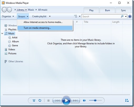
The DLNA streaming on Windows is off by default, so we need to enable it, the easiest is from Windows Media Player, just go to: 

01

Turn on you TV and wait a bit (20s) after click on “Turn on media streaming”:

02

now just click OK (check that you TV is on the list and is allowed), additionally you can change you media library name and disallow devices in your network:

03.00

later on if you want to comeback to this menu to Allow or Disallow a device you can just go to Windows Media Player again:

MEDIA P

An alternative to get to this menu without Windows Media Player is just to go to the Start Windows icone and type “Media streaming options”, and click on the icon with that name:

image


Stream From the PC to the TV

First put your files here:

image

now this video will be available on the Videos section in Windows Media Player, you can select it and cast the video to your TV.

The first time you do this a popup will show on your TV asking if you allow the PC to stream, just select OK, the next time the streaming will automatically.

03.01

when the streaming starts, it will show you the controlls and the progress bar:

03.02

and you should be seeing the video on you TV Smile.

The inconvenience with this is that you have to go to you PC to start the video and maintain the player window open (in the next topic we are going to see how to start videos from the TV).

By default TV you only have the pause control over the video, but you can enable all the controls (Back, Forward, Previous Video, Next Video) with this option:

image


Start Videos From The TV (or another PC)

At this point if you already can stream from the PC to the TV, what you don’t know is that when you enabled streaming in the above section you are also started sharing the files in the Video library (by default only the Video folder) on your PC via DLNA.

Now on the TV you can get the the Videos library’s folders that your PC is sharing.

image

In my TV (Samsung Smart TV) you can find the PC by pressing on the  “Sources” in the TV remote.

As you can see bellow your PC is represented by a media icon, which has you PC name plus the library name you gave when you enabled streaming.

ICONfor other brands it should be similar, but check you TV’s Manual.

When you click the icon you get something like this:

PHOTO_20170425_082017

DLNA categorizes and organizes your media which is normally quite confusing.

The easiest way is to go into the right category in this case Videos, and then select “Folders” that shows you the actual folders that you shared instead of some confusing DLNA organization.

PHOTO_20170425_082039

if you want more folders to show on the TV you can just add them to the library, like this:

05

as you can see on the TV you have de default Video folder and the My Movies folder that we have just added to the Videos library.

image

if you just want to watch the videos in another Windows PC instead of you TV (ex: your Laptop), on that PC you just need to go to “Network”:

image

click on the media device icon, which will open Windows Media Player with the remote library already added to it:

image

and push play


Hope this was helpful !!!!!!! Smile

Saturday, March 1, 2014

ZenOss Core 4 – Installation

Zenoss Core 4 Installation
clip_image001

[1/24/2014: Post has been updated to reflect configuration with CentOS 6.5 and Zenoss Core 4.2.4
This is a sample installation guide for Zenoss Core 4. The single server installation closely aligns with the official Zenoss Core Installation Guide, but it also differs in some areas, and has a little more "glue".
The following components were used for this guide:

· CentOS

· Zenoss Core

· MariaDB

1. Hardware Requirements
You should meet these minimum hardware requirements for a single-server installation of Zenoss 4 Core (up to a 1000 devices):

Deployment Size

Memory

CPU

Storage

1 to 250 devices

4GB

2 cores

1 x 300GB (10K RPM or SSD)

250 to 500 devices

8GB

4 cores

1 x 300GB (10K RPM or SSD)

500 to 1000 devices

16GB

8 cores

1 x 300GB (15K RPM or SSD)

2. Operating System
My solution will be using the CentOS-6.5-x86_64-minimal.iso image. The aim of this image is to install a very basic CentOS 6.5 system, with the minimum number of packages needed to have a functional system. This post won't document the install process for CentOS 6 considering each environment (and associated requirements) is different. The main stages of the OS installation consist of language, storage, hostname, network, timezone, and the root password. 
Note: All commands are run within the context of the root account unless otherwise specified.
Make sure to update the system after the initial boot post install.

# yum -y update

I also install the following packages that are not included by default.

# yum -y install file ntp vim-enhanced man man-pages wget traceroute yum-utils

# hosts file
It's recommended to add a hostname entry (FQDN and short), of the local computer, to the hosts file. You can update the entry manually (via text editor), or run the following set of commands:

# ipv4addr=$(ip -f inet addr show dev eth0 | sed -n 's/^ *inet *\([.0-9]*\).*/\1/p')

# printf "$ipv4addr\t$(hostname -f)\t$(hostname -s)\n" >> /etc/hosts

# unset -v ipv4addr

Verify the entry.

# cat /etc/hosts

127.0.0.1 localhost localhost.localdomain localhost4 localhost4.localdomain4

::1 localhost localhost.localdomain localhost6 localhost6.localdomain6

10.1.206.43 zenoss.corp.example.com zenoss

# SELinux
Zenoss documentation states the requirement that SELinux be disabled. We can accomplish this by changing the SELINUX value to disabled in the /etc/sysconfig/selinux file. Modify the file with your text editor.

# vim /etc/sysconfig/selinux

# This file controls the state of SELinux on the system.

# SELINUX= can take one of these three values:

# enforcing - SELinux security policy is enforced.

# permissive - SELinux prints warnings instead of enforcing.

# disabled - No SELinux policy is loaded.

SELINUX=disabled

# SELINUXTYPE= can take one of these two values:

# targeted - Targeted processes are protected,

# mls - Multi Level Security protection.

SELINUXTYPE=targeted

Reboot the computer for the change to take effect.
After logging in after the reboot, verify SELinux is disabled. Run the following command:

# sestatus

SELinux status: disabled

# Network Time Protocol (NTP)
Time synchronization is an often overlooked, but a very essential, configuration step for new server deployments. In my configuration, I will have my zenoss server sync with an Active Directory domain controller (which holds the PDC emulator FSMO role) on my private network. We will need to modify the ntp.conf file with a text editor and start the NTP daemon process, and also set it for autostart at boot time. Notice I "comment out" the default public pool.ntp.org virtual cluster servers. You may want to leave these enabled if you don't have a particular time source to sync with.

# vim /etc/ntp.conf

...

# Permit all access over the loopback interface. This could

# be tightened as well, but to do so would effect some of

# the administrative functions.

restrict 127.0.0.1

restrict -6 ::1

# Hosts on local network are less restricted.

#restrict 192.168.1.0 mask 255.255.255.0 nomodify notrap

# Use public servers from the pool.ntp.org project.

# Please consider joining the pool (http://www.pool.ntp.org/join.html).

#server 0.centos.pool.ntp.org

#server 1.centos.pool.ntp.org

#server 2.centos.pool.ntp.org

# Use internal NTP Server (AD/DC01)

server 10.1.206.11 iburst

#broadcast 192.168.1.255 autokey # broadcast server

#broadcastclient # broadcast client

#broadcast 224.0.1.1 autokey # multicast server

#multicastclient 224.0.1.1 # multicast client

#manycastserver 239.255.254.254 # manycast server

#manycastclient 239.255.254.254 autokey # manycast client

...

Start the NTP daemon.

# service ntpd start

Starting ntpd: [ OK ]

Set the NTP daemon for autostart at boot time and verify.

# chkconfig ntpd on; chkconfig --list ntpd

ntpd 0:off 1:off 2:on 3:on 4:on 5:on 6:off

We can verify the NTP status by running the following command:

# ntpq -pn

remote refid st t when poll reach delay offset jitter

=================================================

*10.1.206.11 199.180.253.191 3 u 42 64 377 0.429 -69.204 58.561

# Firewall
Zenoss requires the following ports be open on the host firewall:

Port

Protocol

Direction

Description

11211

TCP/UDP

inbound

memcached

8080

TCP

inbound

Web interface

514

UDP

inbound

syslog

162

UDP

inbound

SNMP Traps

25

TCP

inbound

zenmail

Add the rules. It is recommended to add each rule with the iptables command, but I prefer to modify the /etc/sysconfig/iptables file directly with a text editor.

# vim /etc/sysconfig/iptables

# Firewall configuration written by system-config-firewall

# Manual customization of this file is not recommended.

*filter

:INPUT ACCEPT [0:0]

:FORWARD ACCEPT [0:0]

:OUTPUT ACCEPT [0:0]

-A INPUT -m state --state ESTABLISHED,RELATED -j ACCEPT

-A INPUT -p icmp -j ACCEPT

-A INPUT -i lo -j ACCEPT

-A INPUT -m state --state NEW -m tcp -p tcp --dport 22 -j ACCEPT

-A INPUT -m state --state NEW -m tcp -p tcp --dport 11211 -j ACCEPT

-A INPUT -m state --state NEW -m udp -p udp --dport 11211 -j ACCEPT

-A INPUT -m state --state NEW -m tcp -p tcp --dport 8080 -j ACCEPT

-A INPUT -m state --state NEW -m udp -p udp --dport 514 -j ACCEPT

-A INPUT -m state --state NEW -m udp -p udp --dport 162 -j ACCEPT

-A INPUT -m state --state NEW -m tcp -p tcp --dport 25 -j ACCEPT

-A INPUT -j REJECT --reject-with icmp-host-prohibited

-A FORWARD -j REJECT --reject-with icmp-host-prohibited

COMMIT

Restart the firewall service for the changes to take effect.

# service iptables restart

iptables: Flushing firewall rules: [ OK ]

iptables: Setting chains to policy ACCEPT: filter [ OK ]

iptables: Unloading modules: [ OK ]

iptables: Applying firewall rules: [ OK ]

# Oracle Java 6
From a client computer, browse to Oracle's Java Downloads and grab the latest Java Version 6 Linux x64 RPM file.
Transfer the file to the Zenoss server. The command/utility will vary depending on what client OS you're using. I recommend WinSCP or PSCP if using a Windows client. From a Linux or Mac OS X client, we can use the scp command. The following command will copy the file to root's home directory on the destination Zenoss server:

$ scp jre-6u45-linux-x64-rpm.bin root@10.1.206.43:

Back in our terminal for the Zenoss server, we now need to make the binary file executable.

# cd ~

# chmod u+x ./jre-6u45-linux-x64-rpm.bin

Install the Oracle Java Runtime Environment (JRE).

# ./jre-6u45-linux-x64-rpm.bin

Unpacking...

Checksumming...

Extracting...

UnZipSFX 5.50 of 17 February 2002, by Info-ZIP (Zip-Bugs@lists.wku.edu).

inflating: jre-6u45-linux-amd64.rpm

Preparing... ########################################### [100%]

1:jre ########################################### [100%]

Unpacking JAR files...

rt.jar...

jsse.jar...

charsets.jar...

localedata.jar...

plugin.jar...

javaws.jar...

deploy.jar...

Done.

Add the JAVA_HOME variable statement to the end of the system BASH profile file.

# echo 'export JAVA_HOME=/usr/java/default' >> /etc/profile

"Dot" source the system BASH profile file to add the JAVA_HOME variable to the current shell environment.

# . /etc/profile

Verify the variable is set and that Java is installed correctly.

# echo $JAVA_HOME

/usr/java/default

# java -version

java version "1.6.0_45"

Java(TM) SE Runtime Environment (build 1.6.0_45-b06)

Java HotSpot(TM) 64-Bit Server VM (build 20.45-b01, mixed mode)

3. Database
My solution diverges from the official Zenoss documentation. I prefer to deploy MariaDB instead of the standard MySQL server. MariaDB is an enhanced, drop-in replacement for MySQL. Visit theMariaDB website for more information.
Let's first add the MariaDB repo to our local YUM configuration.

# cat >> /etc/yum.repos.d/MariaDB.repo << EOF

> [mariadb]

> name = MariaDB

> baseurl = http://yum.mariadb.org/5.5/centos6-amd64

> gpgkey=https://yum.mariadb.org/RPM-GPG-KEY-MariaDB

> gpgcheck=1

> EOF

Verify.

# cat /etc/yum.repos.d/MariaDB.repo

[mariadb]

name = MariaDB

baseurl = http://yum.mariadb.org/5.5/centos6-amd64

gpgkey=https://yum.mariadb.org/RPM-GPG-KEY-MariaDB

gpgcheck=1

Then also verify the repository is enabled.

# yum repolist

Loaded plugins: fastestmirror

Loading mirror speeds from cached hostfile

* base: mirror.nwresd.org

* extras: mirrordenver.fdcservers.net

* updates: yum.phx.singlehop.com

mariadb | 1.9 kB 00:00

mariadb/primary_db | 15 kB 00:00

repo id repo name status

base CentOS-6 - Base 6,367

extras CentOS-6 - Extras 14

mariadb MariaDB 9

updates CentOS-6 - Updates 373

repolist: 6,763

Let's now install the required packages.

# yum -y install MariaDB-server MariaDB-client

After MariaDB has been installed, modify the MariaDB server.cnf configuration file with some recommended settings from Zenoss.

# vim /etc/my.cnf.d/server.cnf

...

# this is read by the standalone daemon and embedded servers

[server]

# this is only for the mysqld standalone daemon

[mysqld]

max_allowed_packet=16M

innodb_buffer_pool_size=256M

innodb_additional_mem_pool_size=20M

# this is only for embedded server

[embedded]

...

Start the MariaDB server.

# service mysql start

Starting MySQL.. SUCCESS!

Verify MariaDB is set for autostart at boot.

# chkconfig --list mysql

mysql 0:off 1:off 2:on 3:on 4:on 5:on 6:off

4. Zenoss Core
From a client computer, browse to the Zenoss Core site and grab the latest Zenoss Core 4 RPM package for RHEL/CentOS 6 64-bit (v4.2.4 at the date of this post).
Transfer the file to the Zenoss server. The command/utility will vary depending on what client OS you're using. I recommend WinSCP or PSCP if using a Windows client. From a Linux or Mac OS X client, we can use the scp command. The following command will copy the file to root's home directory on the destination Zenoss server:

$ scp zenoss_core-4.2.4-1897.el6.x86_64.rpm root@10.1.206.43:

Back in our terminal for the Zenoss server, install the Zenoss dependencies repositories.

# rpm -Uvh http://deps.zenoss.com/yum/zenossdeps-4.2.x-1.el6.noarch.rpm

Retrieving http://deps.zenoss.com/yum/zenossdeps-4.2.x-1.el6.noarch.rpm

Preparing... ########################################### [100%]

1:zenossdeps ########################################### [100%]

Verify the repositories are enabled.

# yum repolist

Loaded plugins: fastestmirror

Loading mirror speeds from cached hostfile

* base: mirror.nwresd.org

* extras: mirrordenver.fdcservers.net

* updates: yum.phx.singlehop.com

repo id repo name status

base CentOS-6 - Base 6,367

extras CentOS-6 - Extras 14

mariadb MariaDB 9

updates CentOS-6 - Updates 373

zenossdeps-repo Zenoss Dependencies - Base 18

zenossdeps-update-repo Zenoss Dependencies - Updates 0

repolist: 6,781

It's now time to install the Zenoss Core 4 package (and dependency packages).

# cd ~

# yum -y --nogpgcheck localinstall zenoss_core-4.2.4-1897.el6.x86_64.rpm

# memcached, rabbitmq-server, snmpd
Set the services to start automatically at boot, and also interactively start them.

# for svc in memcached rabbitmq-server snmpd; do chkconfig $svc on; service $svc start; done

# Start Zenoss
Run the following command to start Zenoss:

# service zenoss start

At this stage, Zenoss should be ready from a functional perspective. We now need to focus on securing the Zenoss server. 
5. Post-Install
The auto-deploy script offered by Zenoss runs a separate script that secures your Zenoss installation. Since we chose to do a normal install, we will have to manually fetch (and execute) the script. 
Switch to a login shell for the zenoss user.

# su -l zenoss

Verify the zenoss user shell. As a side note, that's an "interesting" UID number for the zenoss user. :-)

$ id

uid=1337(zenoss) gid=500(zenoss) groups=500(zenoss)

Download the secure_zenoss.sh file from GitHub.

$ wget --no-check-certificate https://raw.github.com/osu-sig/zenoss-autodeploy-4.2.3/master/secure_zenoss.sh

Before we run the script, let's get the default passwords for the zenoss user in the global.conf file.

$ egrep 'user|password' $ZENHOME/etc/global.conf | grep -v admin

zodb-user zenoss

zodb-password zenoss

amqpuser zenoss

amqppassword zenoss

zep-user zenoss

zep-password zenoss

Give the secure_zenoss.sh script the execute permission.

$ chmod u+x secure_zenoss.sh

Run the secure_zenoss.sh script. I opted not to change the MySQL (MariaDB) root password at this time. We will be performing that task in the next section.

$ ./secure_zenoss.sh

Restricting permissions on /opt/zenoss/etc/*.conf*

Assigning secure password for global.conf:zodb-password

Assigning secure password for global.conf:amqppassword

Assigning secure password for global.conf:zep-password

Assigning secure password for global.conf:hubpassword

Assigning secure password for hubpassword:admin

MySQL is configured with a blank root password.

Configure a secure MySQL root password? [Yn]: n

Forcing zeneventserver to only listen on 127.0.0.1:8084

Let's verify the passwords have been modified for the zenoss user in the global.conf file.

$ egrep 'user|password' $ZENHOME/etc/global.conf | grep -v admin

zodb-user zenoss

zodb-password 18zmcTgYsA+AjczljwQd

amqpuser zenoss

amqppassword 18zmcTgYsA+AjczljwQd

zep-user zenoss

zep-password 18zmcTgYsA+AjczljwQd

hubpassword 18zmcTgYsA+AjczljwQd

We will also need to modify the password in the zodb_db_main.conf and zodb_db_session.conf files to match the value set for the zodb-password property in the global.conf file. 
First, get the current configuration of these two files.

$ tail -n +1 $ZENHOME/etc/zodb_db_{main,session}.conf

==> /opt/zenoss/etc/zodb_db_main.conf <==

<mysql>

host localhost

port 3306

user zenoss

passwd zenoss

db zodb

</mysql>

==> /opt/zenoss/etc/zodb_db_session.conf <==

<mysql>

host localhost

port 3306

user zenoss

passwd zenoss

db zodb_session

</mysql>

Run the following commands to perform a substitution of the passwd property value for each of the files:

$ zodbpw=$(grep zodb-password $ZENHOME/etc/global.conf | awk '{print $2}')

$ sed -i.orig "5s/zenoss/$zodbpw/" $ZENHOME/etc/zodb_db_{main,session}.conf

$ unset -v zodbpw

Verify the modification was successful.

$ tail -n +1 $ZENHOME/etc/zodb_db_{main,session}.conf

==> /opt/zenoss/etc/zodb_db_main.conf <==

<mysql>

host localhost

port 3306

user zenoss

passwd 18zmcTgYsA+AjczljwQd

db zodb

</mysql>

==> /opt/zenoss/etc/zodb_db_session.conf <==

<mysql>

host localhost

port 3306

user zenoss

passwd 18zmcTgYsA+AjczljwQd

db zodb_session

</mysql>

Exit out of the shell for the zenoss user to return to the root user shell.

$ exit

logout

# MariaDB
The interactive mysql_secure_installation command improves the security of your MariaDB installation. It will allow you to set your MariaDB (MySQL) root password as well as other security related operations.

# mysql_secure_installation

The password for the MariaDB database zenoss user will also need to be set to "sync up" with the previous password modifications. We will use the value set for the passwd property in thezodb_db_* config files.

# mysql -u root -p

Enter password: <mysql_root_password>

Welcome to the MariaDB monitor. Commands end with ; or \g.

Your MariaDB connection id is 234

Server version: 5.5.34-MariaDB MariaDB Server

Copyright (c) 2000, 2013, Oracle, Monty Program Ab and others.

Type 'help;' or '\h' for help. Type '\c' to clear the current input statement.

MariaDB [(none)]> SET PASSWORD FOR 'zenoss'@'localhost' = PASSWORD('18zmcTgYsA+AjczljwQd');

Query OK, 0 rows affected (0.00 sec)

MariaDB [(none)]> \q

Bye

Restart the MariaDB server.

# service mysql restart

Shutting down MySQL. SUCCESS!

Starting MySQL.. SUCCESS!

# RabbitMQ
The following script will ensure the proper Zenoss credentials/permissions are set for the AMQP entities. 
Create the set-rabbitmq-perms.sh script file.

# vim set-rabbitmq-perms.sh

Enter the following information (exclude the line numbers), then save the file:

001 002 003 004 005 006 007 008 009 010 011 012 013 014 015 016 017 018 019 020 021 022 023 024 025

#!/usr/bin/env bash set -e VHOSTS="/zenoss" USER="zenoss" PASS="grep amqppassword \$ZENHOME/etc/global.conf | awk '{print \$2}'" if [ $(id -u) -eq 0 ] then RABBITMQCTL=$(which rabbitmqctl) $RABBITMQCTL stop_app $RABBITMQCTL reset $RABBITMQCTL start_app $RABBITMQCTL add_user "$USER" "$(su -l zenoss -c "$PASS")" for vhost in $VHOSTS; do $RABBITMQCTL add_vhost "$vhost" $RABBITMQCTL set_permissions -p "$vhost" "$USER" '.*' '.*' '.*' done exit 0 else echo "Error: Run this script as the root user." >&2 exit 1 fi

Give the script file the execute permission.

# chmod u+x set-rabbitmq-perms.sh

Run the script.

# ./set-rabbitmq-perms.sh

Stopping node rabbit@zenoss ...

...done.

Resetting node rabbit@zenoss ...

...done.

Starting node rabbit@zenoss ...

...done.

Creating user "zenoss" ...

...done.

Creating vhost "/zenoss" ...

...done.

Setting permissions for user "zenoss" in vhost "/zenoss" ...

...done.

Restart the rabbitmq-server daemon.

# service rabbitmq-server restart

Restarting rabbitmq-server: SUCCESS

rabbitmq-server.

Restart Zenoss.

# service zenoss restart

# Verification
Verify all Zenoss daemons are running.

# su -l zenoss -c 'zenoss status'

Daemon: zeneventserver program running; pid=10564

Daemon: zopectl program running; pid=10662

Daemon: zenrrdcached program running; pid=10667

Daemon: zenhub program running; pid=10730

Daemon: zenjobs program running; pid=10777

Daemon: zeneventd program running; pid=10831

Daemon: zenping program running; pid=10907

Daemon: zensyslog program running; pid=11035

Daemon: zenstatus program running; pid=11026

Daemon: zenactiond program running; pid=11064

Daemon: zentrap program running; pid=11185

Daemon: zenmodeler program running; pid=11196

Daemon: zenperfsnmp program running; pid=11222

Daemon: zencommand program running; pid=11254

Daemon: zenprocess program running; pid=11282

Daemon: zredis program running; pid=11283

Daemon: zenjmx program running; pid=11410

Daemon: zenwin program running; pid=11600

Daemon: zenwinperf program running; pid=11758

Daemon: zeneventlog program running; pid=11910

If the proper permissions have been set for the RabbitMQ zenoss vhost(s), then the following queues should be listed:

# rabbitmqctl -p /zenoss list_queues

Listing queues ...

celery 0

zenoss.queues.zep.migrated.summary 0

zenoss.queues.zep.migrated.archive 0

zenoss.corp.example.com.celeryd.pidbox 0

zenoss.queues.zep.rawevents 0

zenoss.queues.zep.heartbeats 0

zenoss.queues.zep.zenevents 0

zenoss.queues.zep.signal 0

zenoss.queues.zep.modelchange 0

...done.

6. Web Interface Setup Wizard
After the preceding steps have been completed, you are ready to start the Setup Wizard for the initial configuration of customizing Zenoss for your environment. On your client computer, open a web browser and type http://zenoss.corp.example.com:8080 (or http://10.1.206.43:8080) in the address field.

Taken From: http://binarynature.blogspot.pt/2012/11/zenoss-core-4-installation.html

Sunday, October 21, 2012

Cisco Vlan Tunneling (Double Tagging / QinQ)

IEEE 802.1Q Tunneling

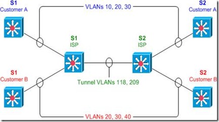
IEEE 802.1Q tunneling can be used to achieve simple layer two VPN connectivity between sites by encapsulating one 802.1Q trunk inside another. The topology below illustrates a common scenario where 802.1Q (or "QinQ") tunneling can be very useful.

clip_image002

A service provider has infrastructure connecting two sites at layer two, and desires to provide its customers transparent layer two connectivity. A less-than-ideal solution would be to assign each customer a range of VLANs it may use. However, this is very limiting, both in that it removes the customers' flexibility to choose their own VLAN numbers, and there may not be enough VLAN numbers (we can only use a maximum of 4,094 or so) available on large networks.

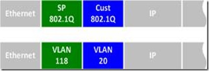
802.1Q tunneling solves both of these issues by assigning each customer a single VLAN number, chosen by the service provider. Within each customer VLAN exists a secondary 802.1Q trunk, which is controlled by the customer. Each customer packet traversing the service provider network is tagged twice: the inner-most 802.1Q header contains the customer-chosen VLAN ID, and the outer-most header contains the VLAN ID assigned to the customer by the service provider.

clip_image004

802.1Q Tunnel Configuration

Before we get started with the configuration, we must verify that all of our switches support the necessary maximum transmission unit (MTU), 1504 bytes. We can use the command show system mtu to check this, and the global configuration command system mtu to modify the device MTU if necessary (note that a reload will be required for the new MTU to take effect).

S1# show system mtu

System MTU size is 1500 bytes

S1# configure terminal

S1(config)# system mtu 1504

Changes to the System MTU will not take effect until the next reload is done.

Next, we'll configure our backbone trunk to carry the top-level VLANs for customers A and B, which have been assigned VLANs 118 and 209, respectively. We configure a normal 802.1Q trunk on both ISP switches. The last configuration line below restricts the trunk to carrying only VLANs 118 and 209; this is an optional step.

S1(config)# interface f0/13

S1(config-if)# switchport trunk encapsulation dot1q

S1(config-if)# switchport mode trunk

S1(config-if)# switchport trunk allowed vlan 118,209

S2(config)# interface f0/13

S2(config-if)# switchport trunk encapsulation dot1q

S2(config-if)# switchport mode trunk

S2(config-if)# switchport trunk allowed vlan 118,209

Now for the interesting bit: the customer-facing interfaces. We assign each interface to the appropriate upper-level (service provider) VLAN, and its operational mode to dot1q-tunnel. We'll also enable Layer two protocol tunneling to transparently carry CDP and other layer two protocols between the CPE devices.

S1(config)# interface f0/1

S1(config-if)# switchport access vlan 118

S1(config-if)# switchport mode dot1q-tunnel

S1(config-if)# l2protocol-tunnel

S1(config-if)# interface f0/3

S1(config-if)# switchport access vlan 209

S1(config-if)# switchport mode dot1q-tunnel

S1(config-if)# l2protocol-tunnel

S2(config)# interface f0/2

S2(config-if)# switchport access vlan 118

S2(config-if)# switchport mode dot1q-tunnel

S2(config-if)# l2protocol-tunnel

S2(config-if)# interface f0/4

S2(config-if)# switchport access vlan 209

S2(config-if)# switchport mode dot1q-tunnel

S2(config-if)# l2protocol-tunnel

We can use the command show dot1q-tunnel on the ISP switches to get a list of all interfaces configured as 802.1Q tunnels:

S1# show dot1q-tunnel

dot1q-tunnel mode LAN Port(s)

-----------------------------

Fa0/1

Fa0/3

Now that our tunnel configurations have been completed, each customer VLAN has transparent end-to-end connectivity between sites. This packet captureshows how customer traffic is double-encapsulated inside two 802.1Q headers along the ISP backbone. Any traffic left untagged by the customer (i.e., traffic in the native VLAN 1) is tagged only once, by the service provider.

Taken From: http://packetlife.net/blog/2010/jul/12/ieee-802-1q-tunneling/

Other:

Friday, October 5, 2012

Wifi on Linux via Command Line

Connect to a wireless network via command line


I know, the first thing you are asking is “Why would I want to have to connect to a wireless network from the command line?” To that question I can give you a simple answer…What if you want to create a script to run that will bring up your wireless network as soon as your desktop is loaded? You could get really complex and create a start up script to load a desktop based on what wirelessaccess point you needed to join. That’s one of the beauties of Linux, if you can dream it, you can do it.
But I am getting too far ahead of myself. Let’s get back to the basics shall we? First I am going to assume that your wireless card was detected by your distribution and has the proper drivers loaded. With that accomplished you will need to have the following tools:
  • ifconfig: Enable your wireless device.
  • iwlist: List the available wireless access points.
  • iwconfig: Configure your wireless connection.
  • dhclient: Get your IP address via dhcp.
The first command you need to use is ifconfig. With this command you are going to enable your wireless device. Most likely your device will be called wlan0. So in order to enable this you would enter the command (as root):

ifconfig wlan0 up

You won’t see any feedback unless there is a problem.
The next step is to scan for your wireless network to make sure it is available. Do this with the following command:

iwlist wlan0 scan

With this command you will see output like the following:

Cell 01 - Address: 00:21:43:4E:9B:F0
ESSID:"HAIR STROBEL"
Mode:Master
Channel:5
Frequency:2.432 GHz (Channel 5)
Quality=100/100? Signal level:-45 dBm? Noise level=-95 dBm
Encryption key:on
IE: WPA Version 1
Group Cipher : TKIP
Pairwise Ciphers (1) : TKIP
Authentication Suites (1) : PSK
IE: IEEE 802.11i/WPA2 Version 1
Group Cipher : TKIP
Pairwise Ciphers (1) : CCMP
Authentication Suites (1) : PSK
Bit Rates:1 Mb/s; 2 Mb/s; 5.5 Mb/s; 11 Mb/s; 22 Mb/s
6 Mb/s; 9 Mb/s; 12 Mb/s; 18 Mb/s; 24 Mb/s
36 Mb/s; 48 Mb/s; 54 Mb/s
Extra:tsf=000002f1d9be01b7

So you know this network is available. From the above output you can also see this network is employing WPA2, so you will need a passkey. If you don’t know that passkey, you are out of luck (which would be the case no matter if you were using a front end in Linux, Windows, or Mac.)

Now it’s time to configure your connection. To do this issue the command:

iwconfig wlan0 essid NETWORK_ID key WIRELESS_KEY

Where NETWORK_ID is the ESSID of the network with which you want to connect and WIRELESS_KEY is the security key needed to connect to the wireless access point.

Note: iwconfig defaults to using a HEX key. If you want to use an ascii key you will have to add the “s:” prefix to your key like so:

iwconfig wlan0 essid NETWORK_ID key s:WIRELESS_KEY

Now that you have your configuration set, it’s time to get an IP address with the help of dhclient. Issue the command:

dhclient wlan0

If no output is reported there are no errors. You should now be up and running.


Make it a script

Of course who wants to type out all of those commands. Instead of doing this you could create a script for this like so:

#! /bin/bash
ifconfig wlan0
iwconfig wlan0 essid NETWORK_ID key WIRELESS_KEY
dhclient wlan0

Where NETWORK_ID is the actually essid of the network and WIRELESS_KEY is the security key for that network. Save this script with the filename wireless_up.sh and then make this script executable with the command:

chmod u+x wireless_up.sh

You can make this a global command by placing this script in /usr/local/bin. You can now issue the command wireless_up.sh from anywhere in your directory structure and it will run, connecting you to the configured wireless access point.

If you frequent many wireless access points you can create a script for each one giving them each unique names. By doing this, when you need to connect to a specific access point, just run the script associated with that access point and you’re good to go.

Taken From: http://www.ghacks.net/2009/04/14/connect-to-a-wireless-network-via-command-line/

Thursday, March 15, 2012

Enterasys Switches Crash Course

[ Login & Password ]

If admin / siemens doesn't work, try admin/none
default, no pwd, just enter
user : admin, rw, ro


C2(SU)-> set system login 'username' {super-user|read-write|read-only}{enale|disable}
C2(SU)-> clear system login 'username'
C2(SU)-> show system login
for rw and ro = set password
for admin = set system login
C2(SU)-> set password rw
C2(SU)-> set system password length 7


[ Assign IP address ]

C2(SU)-> set ip address x.x.x.x mask x.x.x.x gateway x.x.x.x
C2(SU)-> clear ip address
[ Webview ]

Default : enable
C2(SU)-> show webview : to see status of webview (default enable)
C2(SU)-> set webview enable : to enable webview
- login : http://172.16.2.10
C2(SU)-> show webview
WebView is Enabled


[ Set time ]
C2(SU)-> set time 7:50:00
C2(SU)-> set summertime enable

[ Set prompt ]
C2(SU)-> set prompt "switch 1"

[ Set system contact ]
C2(SU)-> set system name "Enterasys-C2.1"
C2(SU)-> set system location "Main Bldg 2nd Floor"
C2(SU)-> set system contact "ipBalance Admin (            888-999-0000      )Mr.admin@ipBalance.com This e-mail address is being protected from spambots. You need JavaScript enabled to view it "

[ Save configuration ]
C2(SU)-> save config

[ Configure ]
C2(SU)-> configure configs/Jan1_2004.cfg

[ Set command ]
C2(SU)-> set switch description 1 : describe switch name or location
C2(SU)-> set ip address {x.x.x.x} mask {255.255.255.0} gateway {x.x.x.x}
C2(SU)-> clear ip address
C2(SU)-> set time [mm/dd/yyyy][hh:mm:ss]
C2(SU)-> set logout 10 : closing session idle in 10 min
C2(SU)-> set port [enable|diable]
C2(SU)-> set port duplex
C2(SU)-> set cdp state disable fe.1.2
C2(SU)-> set cdp state disable fe.1.3
C2(SU)-> set vlan create 2
C2(SU)-> set vlan create 3
C2(SU)-> set vlan name 1 Management
C2(SU)-> set vlan egress 1 fe.1.1 tagged
C2(SU)-> set vlan egress 1 fe.1.22 untagged
C2(SU)-> set vlan egress 2 fe.1.1 tagged
C2(SU)-> set vlan egress 2 fe.1.2-14 untagged
C2(SU)-> set port alias fe.1.1 'To Computer room N1.1 Port 2'
C2(SU)-> set port vlan fe.1.14 2

[ show ]
C2(SU)-> show config port
C2(SU)-> show switch
C2(SU)-> show switch status 1
C2(SU)-> show system
C2(SU)-> show system hardware : to get serial#, MAC, Firmware version etc
C2(SU)-> show system utilization {cpu|storage}
C2(SU)-> show time
C2(SU)-> show console
C2(SU)-> show telnet
C2(SU)-> show system login : user login account info
C2(SU)-> show system lockout
C2(SU)-> show ip address
C2(SU)-> show ip protocol : shown "system IP address acquisition method: dhcp
C2(SU)-> show config port
C2(SU)-> show cdp
C2(SU)-> show port fe.1.14 (ex, show port *.*.*)
C2(SU)-> show port status fe.1.14 : shown on status of information for fe.1.14
C2(SU)-> show port counters fe.1.14
C2(SU)-> show port negotiation fe.1.14
C2(SU)-> show port broadcast fe.1.14
C2(SU)-> show spantree stats
C2(SU)-> show boot system

[ Lag ]
C2(SU)-> show lacp lag 0.1
C2(SU)-> set lacp enable
C2(SU)-> set lacp asyspri 1000
C2(SU)-> set lacp aadminkey lag.0.1 2000
C2(SU)-> set lacp static lag.0.6 fe.1.6
C2(SU)-> set lacp singleportlag enable
C2(SU)-> set port lacp fe.3.16 aadminkey 3555

[ Clear ]
C2(SU)-> clear config
C2(SU)-> clear vlan 3
C2(SU)-> clear vlan name 9
C2(SU)-> clear port vlan fe.1.3,fe.1.11
C2(SU)-> clear vlan egress 1 fe2.1
C2(SU)-> clear VNRAM

[ Reset ]
C2(SU)-> reset or reset 1 : reload switch 1

[ Configuration example ]
C2(SU)-> dir
C2(SU)-> show configuration outfile configs/
C2(SU)-> copy configs/ tftp://192.168.77.101/
using notepad, modify config
C2(SU)-> copy tftp://192.168.77.101/jan11_2006.cfg configs/jan11_2006.cfg
C2(SU)-> dir
C2(SU)-> configure configs/  : unit will reboot onto the modified config file
C2(SU)-> configure configs/Jan11_2006.cfg  :  to execute the"jan11_2006.cfg" configurationn file
C2(SU)-> delete configs/jan11_2006.cfg
C2(SU)-> clear config all
C2(SU)-> clear NVRAM
C2(SU)-> show snmp persistmode manual : manual save config
C2(SU)-> save config

[ Login & Password ]

If admin / siemens doesn't work, try admin/none
default, no pwd, just enter
user : admin, rw, ro

A2(SU)-> set system login 'username' {super-user|read-write|read-only}{enale|disable}
A2(SU)-> clear system login 'username'
A2(SU)-> show system login
for rw and ro = set password
for admin = set system login
A2(SU)-> set password rw
A2(SU)-> set system password length 7

[ Assign IP address ]
A2(SU)-> set ip address x.x.x.x mask x.x.x.x gateway x.x.x.x
A2(SU)-> clear ip address

[ Webview ]
Default : enable
A2(SU)-> show webview : to see status of webview (default enable)
A2(SU)-> set webview enable : to enable webview
- login : http://172.16.2.10
A2(SU)-> show webview
WebView is Enabled
[ Set time ]
A2(SU)-> set time 7:50:00
A2(SU)-> set summertime enable
[ Set prompt ]
A2(SU)-> set prompt "switch 1"
[ Set system contact ]
A2(SU)-> set system name "Enterasys-A2.1"
A2(SU)-> set system location "Main Bldg 2nd Floor"
A2(SU)-> set system contact "ipBalance Admin (            888-999-0000      ) Mr.admin@ipBalance.com "
 
[ Save configuration ]

A2(SU)-> save config

[ Configure ]
A2(SU)-> configure configs/Jan1_2004.cfg
[ Set command ]
A2(SU)-> set switch description 1 : describe switch name or location
A2(SU)-> set ip address {x.x.x.x} mask {255.255.255.0} gateway {x.x.x.x}
A2(SU)-> clear ip address
A2(SU)-> set time [mm/dd/yyyy][hh:mm:ss]
A2(SU)-> set logout 10 : closing session idle in 10 min
A2(SU)-> set port [enable|diable]
A2(SU)-> set port duplex
A2(SU)-> set cdp state disable fe.1.2
A2(SU)-> set cdp state disable fe.1.3
A2(SU)-> set vlan create 2
A2(SU)-> set vlan create 3
A2(SU)-> set vlan name 1 Management
A2(SU)-> set vlan egress 1 fe.1.1 tagged
A2(SU)-> set vlan egress 1 fe.1.22 untagged
A2(SU)-> set vlan egress 2 fe.1.1 tagged
A2(SU)-> set vlan egress 2 fe.1.2-14 untagged
A2(SU)-> set port alias fe.1.1 'To Computer room N1.1 Port 2'
A2(SU)-> set port vlan fe.1.14 2
[ show ]
A2(SU)-> show config port  :
A2(SU)-> show switch
A2(SU)-> show switch status 1
A2(SU)-> show system
A2(SU)-> show system hardware : to get serial#, MAC, Firmware version etc
A2(SU)-> show system utilization {cpu|storage}
A2(SU)-> show time
A2(SU)-> show console
A2(SU)-> show telnet
A2(SU)-> show system login : user login account info
A2(SU)-> show system lockout
A2(SU)-> show ip address
A2(SU)-> show ip protocol : shown "system IP address acquisition method: dhcp
A2(SU)-> show config port
A2(SU)-> show cdp
A2(SU)-> show port fe.1.14 (ex, show port *.*.*)
A2(SU)-> show port status fe.1.14 : shown on status of information for fe.1.14
A2(SU)-> show port counters fe.1.14
A2(SU)-> show port negotiation fe.1.14
A2(SU)-> show port broadcast fe.1.14
A2(SU)-> show spantree stats
A2(SU)-> show boot system
[ Lag ]
A2(SU)->
show lacp lag 0.1
A2(SU)-> set lacp enable
A2(SU)-> set lacp asyspri 1000
A2(SU)-> set lacp aadminkey lag.0.1 2000
A2(SU)-> set lacp static lag.0.6 fe.1.6
A2(SU)-> set lacp singleportlag enable
A2(SU)-> set port lacp fe.3.16 aadminkey 3555
[ Clear ]
A2(SU)-> clear config
A2(SU)-> clear vlan 3
A2(SU)-> clear vlan name 9
A2(SU)-> clear port vlan fe.1.3,fe.1.11
A2(SU)-> clear vlan egress 1 fe2.1
A2(SU)-> clear VNRAM
[ Reset ]
A2(SU)-> reset or reset 1 : reload switch 1

[ Configuration example ]
A2(SU)-> dir
A2(SU)-> show configuration outfile configs/
A2(SU)-> copy configs/ tftp://192.168.77.101/
using notepad, modify config
A2(SU)-> copy tftp://192.168.77.101/jan11_2006.cfg configs/jan11_2006.cfg
A2(SU)-> dir
A2(SU)-> configure configs/  : unit will reboot onto the modified config file
A2(SU)-> configure configs/Jan11_2006.cfg  :  to execute the"jan11_2006.cfg" configurationn file
A2(SU)-> delete configs/jan11_2006.cfg
A2(SU)-> clear config all
A2(SU)-> clear NVRAM
A2(SU)-> show snmp persistmode manual : manual save config
A2(SU)-> save config

[ Default Login & Password ]
Here is default  login passwords of the most Enterasys Switches.
A-Series, B-Series and C-Series Enterasys Switches.
User : admin
Password : [empty]
Try below commends to see current login

Enterasys_A2(SU)-> show system login
Password history size: 0 
Password aging        : disabled  
Username     Access           State  
admin          super-user      enabled 
ro               read-Only       enabled 
rw              read-write       enabled
To add user 'Chris' as a super-user
  Enterasys_A2(SU)-> set system login chris super-user enable
  Enterasys_A2(SU)-> show system login

Password history size: 0
Password aging        : disabled
Username     Access           State
admin       super-user          enabled
ro            read-Only           enabled
rw           read-write           enabled
chris         super-user           enabled
To delete user 'chris' from list

  Enterasys_A2(SU)-> clear system login chris

If you want to change password length 7
  Enterasys_A2(SU)-> set system password length 7

[ Syslog Server ]
While I was testing Splunk, I need to add more devices to Splunk index pages. This example shows how to configure Enterasys Switch to forward syslog message to the server. It's simple and easy to setup.
In this example, server's IP is 192.168.77.13 and UDP port 514 is used. Severity level is 8.

  Enterasys(su)>set logging server 1 ip-addr 192.168.77.12 port 514 severity 8 state enable

To verify

 
  Enterasys(su)>show logging server

IP Address    Facility   Severity      Description  Port  Status 
--------------------------------------------------------------- 1 192.168.77.12    local4    debugging(8)     default     514   enable
If you want to change default value to facility local 5 and severity 5, configure below.

Enterasys(su)>set logging default facility local 5 severity 5
To see currently logging severity levels for all applications on your devices, type below commands

Enterasys(su)>show logging application all

        Application   Current Severity Level
---------------------------------------------
89      CLIWEB                   6
90      SNMP                     6
91      STP                      6
92      Driver                   6
93      System                   6
94      Stacking                 6
112     UPN                      6
118     Router                   6
1(emergencies)  2(alerts)       3(critical)
4(errors)       5(warnings)     6(notifications)
7(information)  8(debugging)

[ Port Mirroring ]
source port 1/13
destinaion port 1/10

Console(Config)#interface Ethernet 1/1
Console(Config-if)#port monitor Ethernet 1/4
Console(Config-if)#

[ Upgrade Firmware ]
As you know Enterasys was named Cabletron company long long time ago. I guess more than decade Cabletron was one of strong vendor on switches market at that time. Due to I had really good experience with Cabletron product, I trust Enterasys's product line. Actually, I installed many Enterasys switches since 2005. Today, I just want to share a tip to upgrade firmware on Enterasys switches. Compare to generic 3rd party switch vendors, Enterasys release new firmware more often. Well, some of people might say due to all lot of bugs, but I like to say "Diligent and effort" (too much?).There are detailed documents from vendor, but this guide would be easier for beginner. Well, lets see what the steps to complete upgrading firmware are.
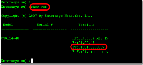
1. Find out what model of switch you are upgrading and what is current version of firmware running on the switch. Type "Show version" from the prompt.

- Model : C3G124-48
- Firmware : 01.01.02.0007

clip_image005
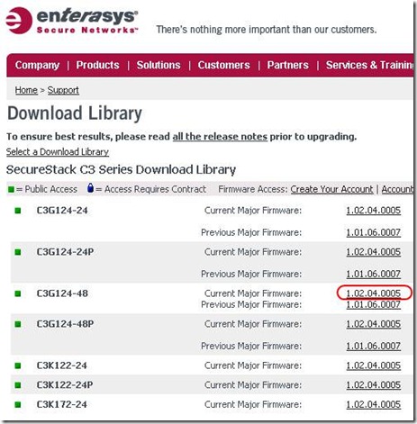
2. Go to the website "www.enterasys.com" and download proper firmware from the download library. and extract firmware to any folder your tftp server will use.

clip_image007

3. Assign IP address on the Enterasys switch in order to communicate with you computer which is running tftp server.
ex) computer 192.168.1.47, Enterasys switch is 192.168.1.8, default gateway .254

"set ip address 192.168.1.8 mask 255.255.255.0 gateway 192.168.1.254"


clip_image008
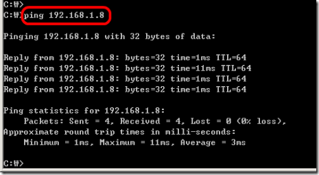
4. Ping the Enterasys switch from your computer.

clip_image009
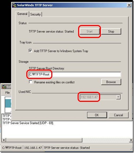
5. Execute tftp server. (If you don't have, just down one from solarwinds)

clip_image011
6. Copy firmware from tftp server

Enterasys(su)->copy tftp://192.168.1.47/c3-series_01.02.04.0005 system:image
- I will take time...to be done (few minutes)

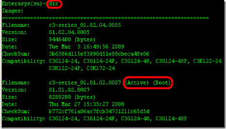
7. From the switch, make sure new firmware is uploaded and check which firmware version is on active.

clip_image012
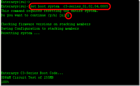
8. Type to "set boot system c3-series_01.02.04.0005" to booting up switch with new firmware(active).
B2(su)>>set boot system c3-series_01.02.04.0005
Do you want to replace ? (y/n) y
Automatically Enterasys switch will reboot.

clip_image013

9. Confirm now, new firmware is on active status.
The complete CLI reference manuals can be found at:

Enterasys C2 (Configuration Guide) :
http://www.penteknoloji.com.tr/destek/c2/1.pdf
Enterasys C3 (Configuration Guide): http://www.penteknoloji.com.tr/destek/c3/2.pdf