Showing posts with label network. Show all posts

Sunday, February 12, 2012

Iperf Commands for Network Troubleshooting

Iperf is a very useful utility for network troubleshooting.  In this post I’ll share my list of Iperf commands that I have found useful.

What is Iperf?

Iperf is a network performance utility that can generate both TCP and UDP traffic for testing bandwidth, latency, and packet loss.  Iperf is very powerful and can easily generate enough traffic to saturate a 1Gb, or 10Gb connection.  Iperf is included with most Linux distributions but you can compile Iperf for windows if needed.

In order to use Iperf you’ll need to setup an Iperf server, Iperf clients can then connect to the server in order to run tests.  By default Iperf is uni-directional and sends data from the client to the server.

In my examples I’m using 192.168.1.1 as the address of my Iperf server.

Running iperf -s will setup a basic Iperf server, you can also run Iperf in daemon mode by running iperf -D.

Basic TCP Unicast Test

The simplest test you can do with Iperf is a basic TCP test.  By default the server will use a  TCP window size of 85.3KB.  The client will connect to the server on port 5001 using a TCP window size of 16KB.  The -t option instructs the client to run the test for 30 seconds instead of the default of 10 seconds.

[Server] – iperf -s -i 1

[Client] – iperf -c 192.168.1.1 -t 30

Parallel TCP connections

Parallel connections can be useful if you need to saturate the bandwidth of a link.  The bandwidth of a single TCP session can be greatly affected by the size of the receive window and the latency of the link.

To enable parallel connections add the -P flag to the Iperf client parameters followed by the number of connections you want.  Make sure to use a capital P, lowercase p will specify a different port number to connect on.

[Server] – iperf -s -i 1

[Client] – iperf -c 192.168.1.1 -t 30 -P 10

UDP Mode

Testing with UDP packets requires the -u flag on both the client and server.  The cool thing about UDP mode is that you don’t have to use a server.  Instead you can use the interface counters on your switches.  You can also specify the destination address to be a multicast group, the default TTL for multicast is 1 (be careful).  To set a different TTL use the -T option on the client.

If you want to test for jitter and packet loss then you should use UDP mode.

[Server] – iperf -s -i 1

[Client] – iperf -c 192.168.1.1 -t 30 -u

In UDP mode iperf defaults to 1Mb/s, you can tell it to use more bandwidth by using the -b flag followed by the number of bits/sec to send.  For example, iperf -c 192.168.1.1 -u -b 100000000 would send at a rate of 100Mb/s.

Bidirectional testing

If you want to test throughput both to and from the server at the same time you can use the -d option to run a bidirectional test.  This will send data to the server, and receive data from the server simultaneously.

[Server] – iperf -s -i 1

[Client] – iperf -c 192.168.1.1 -t 30 -d

Bandwidth limiting

If you need to test for packet loss or other problems at a specific rate of bandwidth you can use the -b flag to specify the maximum throughput in bits/second.

[Server] – iperf -s -i 1

[Client] – iperf -c 192.168.1.1 -t 30 -b 100000

Transfer 1GB of data then stop

Instead of running the test for a specific period of you can instruct Iperf to stop running after trasfering a certain amound of data.  The example below will send 1GB (1024³) of data to the server and then stop

[Server] – iperf -s -i 1

[Client] – iperf -c 192.168.1.1 -n 1073741824

Stop the iPerf server

To kill the iperf server just press CTRL+C in your terminal and it will interrupt the process.

If you are running iPerf in daemon mode you’ll need to find the process ID first

ps -ef | grep iperf
root     16186     1  0 22:00 ?        00:00:00 iperf -s -D

Then kill it

kill 16186

Useful References

Energy Sciences Network Host Tuning Guide

Using Iperf – Guide by Jon Dugan

Taken From: http://samkear.com/networking/troubleshooting/iperf-commands-network-troubleshooting

Friday, January 27, 2012

Plop – Boot USB Disks on Old Hardware and VMware

Using Plop Boot Manager for USB Boot

For PLOP USB Disks Booting on VMWARE check this post: http://myhowtosandprojects.blogspot.com/2011/12/boot-from-usb-disk-in-vmware.html

clip_image002

Portability is a huge advantage that Linux enjoys over most other desktop operating systems as most major distros work very well when installed to a flash drive. However, there are still machines in service that just won't play ball when it comes to USB booting. Fortunately, I found a nice little utility that can work around this problem.


Carrying data around on a flash drive is handy, but with Linux, it's possible to carry around an entire work environment. Unfortunately, however, there are some older systems that won't boot from USB. For example, I have a Sempron 3000+ system with 2GB of RAM that won't boot from USB, even though it's a usable system for some things. If the BIOS doesn't support booting from a flash drive, there's not much that GRUB can do as it doesn't contain any drivers and relies on the BIOS to find bootable media.


Plop Boot Manager aims to overcome these limitations. Like most boot managers, it presents a selection menu to choose the boot partition when the machine first starts up. As it contains its own USB drivers, you can use it to convince older hardware to boot from a device such as a flash drive. It's a quite a flexible piece of software. For example, you can set it up to be loaded by GRUB or the Windows boot loader menu or even something more exotic such as loading Plop from from a floppy disk drive in order to initiate a network boot. In this example, I'll just be documenting one single use case in which I used it to enable an older machine to boot from a USB drive.

clip_image004
Standard disclaimer: If you're carrying out a job like this, a single mistake or one bug in the software can easily wipe the contents of the entire disk. Back up valuable data.

clip_image006
In this case, I installed it to the MBR (Master Boot Record) as this is the simplest option. A word of warning here: when installed to the MBR, it will overwrite an existing GRUB installation if it too was placed in the MBR. As Plop isn't a Linux loader, this means that Linux will no longer work. In other words, you will have to reinstall GRUB onto the Linux boot partition itself, if you don't already have it working like that. There might be a slight problem here as USB keyboards wont work until the operating system itself has booted. This means that you can't actually select anything from the Grub menu if you are using a USB keyboard, which should’t be a huge problem for most uses. Obviously, Plop Boot Manager can select between operating systems. An existing Windows installation should continue to work without modification.

clip_image008

Within the archive, there are a few directories with the files needed for different types of installation. In this case I took the ISO installer image (all 480k of it) and burnt it to a CDR. As I said, if this isn't an option with the machine that you're working with, you can install from within an operating system that is already running on the computer. As with all of the system, the installer uses a flashy mixture of text mode and graphics. It's a simple system and it installs very quickly.


Rebooting, you're presented with the installer itself with options for booting from different types of media. As hoped, this allowed me to boot Xubuntu from the USB flash drive. One limitation of the program is that it can't handle booting from USB DVD/CDROM drives which is a shame. It's an interactive boot manager and you can reconfigure it on the fly to change things like appearance and default boot options.


Plop Boot Manager is a versatile piece of software. Risking the ire of Linux graybeards by saying it, I've often wished that more Linux distros made use of something a bit friendlier than the perennial GRUB. If you work with a lot of older hardware and would like to boot from a memory stick, the the ISO version of the boot loader on a CDR might be worth adding to your bag of tricks.


I've only scratched the surface of what Plop can do. Hit the docs for a full feature list.

______________________

UK based freelance writer Michael Reed writes about technology, retro computing, geek culture and gender politics.

Taken From: http://www.linuxjournal.com/content/using-plop-boot-manager-usb-boot

Wednesday, September 23, 2009

PPPoE and DSL Connections - Public IP

The Point-to-Point Protocol over Ethernet (PPPoE) is a network protocol for encapsulating Point-to-Point Protocol (PPP) frames inside Ethernet frames. It is used mainly with DSL services where individual users connect to the DSL modem over Ethernet and in plain Metro Ethernet networks. It was developed by UUNET, Redback Networks, and RouterWare and is available as an informational RFC 2516.


Figure 1 (click to enlarge)

Imagine that you have the scenario on Figure 1 where you have DSL Router/Bridge (ISR - Thomson st516 v6), where one interface connects to a Router / Firewall on your private network, and the other to your ISP, wher this one has the Public IP provided by your ISP.

Now imagine that the Router / Firewall has the ability to make VPNs. And you want make one, but you have a problem, you don't have a Public IP on the interface you want to end the VPN. This is where PPPoE, migth be usefull. Instead off starting the PPPoE conection from the DSL Router/Bridge (ISR), you start it from you Router / Firewall, in order for it to get the public IP from the ISP on it's interface. For this on the DSL Router/Bridge (ISR), you need to change the mode from Router to Bridge and input the your ISP's ATM VPI/VCI, in order to make this a pass through only device. And off course configure the PPPoE connection on your Router / Firewall, with you account data (login and username) and your IPS's ATM VPI/VCI. Now your Router / Firewall has an Public Ip and now you can configure your VPN service.


Figure 2 (click to enlarge)

The same applyes, to the scenario on Figure 3, where instead off a Router / Firewall you have a computer running Windows or Linux, that has for example a Web Server, that needs to be accessible from the internet an for that you need a Public Ip, on it's interface. Don' t forget that on DSL Router/Bridge (ISR), you need to change the mode from Router to Bridge and input the your ISP's ATM VPI/VCI, in order to make it a pass through only


Figure 3 (click to enlarge)


Configuring PPPoE on Windows

You can install the PPPoE client just like you install any other dial-up networking connection. To create a PPPoE client connection, follow these steps:

1. Click Start, click Control Panel, and then double-click Network and Internet Connections.
2. Click Network Connections, and then click Create a new connection in the Network Tasks pane.
3. After the Network Connection Wizard starts, click Next.
4. Click Connect to the Internet, and then click Next.
5. Click Set up my connection manually, and then click Next.
6. Click either Connect using a broadband connection that requires a user name and password or Connect using a broadband connection that is always on.
7. Type the Internet service provider (ISP) name that your ISP provided, and then clickNext.
8. Type the user name that the ISP provided.
9. Type the password that the ISP provided.
10. Type the password one more time to confirm it, and then click Next.
11. Click Add a shortcut to this connection to my desktop.
12. Click Finish to complete the wizard.


Configuring PPPoE on Linux

=======================================
ALL DEVICES FOUND?
I found 3 ethernet devices:
eth0
pan0
wlan0
Are all your ethernet interfaces listed above? (If No, modconf will be started so you can load the card drivers manually
Yes

=======================================
Most people using popular dialup providers prefer the options 'noauth' and 'defaultroute' in their configuration and remove the 'nodetach' option. Should I check your configuration file and change these settings where neccessary?

Yes


=======================================
Please enter the username which you usually need for the PPP login to your provider in the input box below. If you wish to see the help screen, delete the username and press OK.
username________________________________________________

your_username

=======================================
Please enter the password which you usually need for the PPP login to your provider in the input box below. NOTE: you can see the password in plain text while typing.

your_password

=======================================
You need at least one DNS IP address to resolve the normal host names. Normally your provider sends addresses of useable servers when the connection is established. Would you like to add these addresses automatically to the list of nameservers in your /etc/resolv.conf file? (recommended)

Yes

=======================================
Many providers have routers that do not support TCP packets with a MSS higher than 1460. Usually, outgoing packets have this when they go through one real Ethernet link with the default MTU size (1500). Unfortunately, if you are forwarding packets from other hosts (i.e. doing masquerading) the MSS may be increased depending on the packet size and the route to the client hosts, so your client machines won't be able to connect to some sitesThere is a solution: the maximum MSS can be limited by pppoe. You can find more details about this issue in the documentation. Should pppoe clamp MSS at 1452 bytes? If unsure, say yes (If you still get problems described above, try setting to 1412

Yes

=======================================
Your PPPD is configured now. Would you like to start the connection at boot time?

Yes

=======================================
Now, you can make a DSL connection with "pon dsl-provider" and terminate it with "poff". Would you like to start the connection now

Yes

=======================================
The DSL connection has been triggered. You can use the "plog" command to see the status or "ifconfig ppp0" for general interface info.

OK


Based on:

Tuesday, July 7, 2009

Setting up a dial-up VPN on the Juniper NetScreen Remote (client)

Note: I tried the tutorial on a Juniper SSG350M, with FW 6.0.0r4.0, and it worked althoug it's not the equipement on the tutorial


Note: To see the pictures at full quality just click on them.


This article was graciously contributed by mwdmeyer which was originally posted on his site here.

I've been getting lots of hits to the post about a site to site VPN setup with a netscreen. So I've decided to do one for a dial-up VPN user connecting to a netscreen.

A dial-up user is anyone who needs access into the network and has a dynamic ip address. We don't wish to be able to access them (the dial-up user) from within the network. This is how we setup most connections at work. This allows people to access file shares and outlook (without the need to setup RPC over HTTP).

Background

  • Netscreen 5GT running ScreenOS 5.4.0r1 (Should be the same process for any netscreen running ScreenOS 5.x)
  • Netscreen Remote 8.7 (The Windows VPN client)
  • Local Network (the one in which the vpn users want to access) of 10.0.0.0/22 (10.0.0.0 - 10.0.3.255)
  • External Address of 59.167.253.89

Setting up the Netscreen

1) First we need to create a user. This can be found in Objects -> Users -> Local (Note: Follow the screen shot below, you don't need a password here, you do need the IKE User info though)


So we have our user, Test.User

2) Create Phase 1 of the VPN tunnel. This can be found in VPNs -> AutoKey Advanced -> Gateway (Note: Security level is set to custom, password for VPN is entered here, Outgoing interface is your untrust interface).


3) Now we'll modify the advanced settings. Click Advanced (Note: We're using DES and MD5 here. Mode is set to Aggressive)


Now click return and okay to save your settings.

4) Now we'll create the Phase 2 information. This can be found in VPNs -> AutoKey IKE (Note: Security level is set to custom, Remote Gateway is set to "Test.UserP1")


5) Now we'll modify the advanced settings. Click Advanced (Note: We're using DES and MD5 here. Replay Protection is on)


Now click return and okay to save your settings.

6) Now we'll need to create a policy. This will go from untrust to trust. This can be found in Policies.


Click new (Note: Source Address is Any-IPv4 or just Any if IPv6 is disabled, Destination Address is your local subnet, tunnel the connection though the VPN user "Test.UserP2")


Now the Netscreen has been setup.

Setting up Netscreen Remote

1) Open the policy editor in Netscreen Remote

NetScreen Remote 1

2) Create a new connection (Note: Type in the remote subnet details and set the secure gateway to your netscreens external address)


3) Now we'll setup the login details (Note: The Certificate is None, The ID Type is Domain Name and the value is "Test.User")


4) Now click Pre-Shared Key (Note: Type in the password you used when setting up the connection in the netscreen)


5) Now we'll set the connection to aggressive (Note: Enable PFS, DH is Group 2 and Enable Replay Dection)


6) Now we'll setup the Phase 1 details (Note: We're using DES and MD5 here. SA Life is 28800 seconds)


7) Now we'll setup the Phase 2 details (Note: The SA Life here is 3600 Seconds)


8) Save the settings and Test!

That should be all you need to do.

Notes

  • The VPN may not work behind some NAT routers. You can try turning on NAT-T within the netscreen, although I find it doesn't normally work.
  • Make sure the details in the Netscreen and Netscreen Remote Match (i.e Phase 1 policies etc)
  • You can check the logs from both Netscreen and Netscreen Remote
  • You cannot connect to the VPN while within the local subnet
  • Netscreen Remote should be disabled when you're directly connected to the network
  • Only traffic for the subnet is passed over the VPN.


Taken From:
http://www.juniperforum.com/index.php?page=20
Added minor correction in te policy source that has to be "Dial Up"

Friday, June 12, 2009

Backup Files With Rsync and Grsync

There are, of course, numerous backup solutions you can use, from the simple and free to the complex and expensive, as well as everything in between. The technology behind most backup systems, however, tends to be much more limited. Using classic tools, such as tar and gzip, to back up and compress is still very common under the surface of much more complex tools. This is true even when using network resources. In the end, you are backing up from one machine to another. Many people I know, including those with small businesses, do this for their regular backups. Machine A backs to machine B, which backs to C, which backs to A. The machines, and their drives, are all part of a network. Hey, instant cloud, and you probably didn't know you had one.

This is where rsync, another popular backup tool, shows its worth. As the name implies, rsyncs keep a backup copy of your data, in sync with the original. It can do it locally, from one physical drive to another, or across your network. Because only those files that have been modified are transferred, the process can be very quick. You can do this with single files, whole directories and subdirectories, while maintaining file ownership and permissions, links, symbolic links and so on. rsync has its own transport, or you can use OpenSSH to secure the transfer, and (of course) there are some great front-end, graphical tools to make the process a little slicker.

You can find rsync at rsync.samba.org, but you probably don't even have to look that far. Many distributions load it when you install your system. If not, check your installation disks or simply pick it up from your distribution's repositories. Before I explain how to rsync your data to your own personal cloud, let me show you how easy it is to create a synchronized backup of your data from one directory to another (or one drive to another):

rsync -av important_stuff/ is_backup

In the above example, rsync copies everything in the directory important_stuff into another directory (or folder) called is_backup. Most of you will have figured out that the -v means verbose copy. The -a option hides some amount of complexity in that it is the same as using the -rlptgoD flags. In order, this means that rsync should do a recursive copy; copy symbolic links; preserve permissions, modification times and group and owner information; and, with the final D, copy special files (device and block). When you press Enter, files go scrolling by, after which you see something like this:

sending incremental file list
./
CookingJul08.tgz
CookingJul2008_albums.odt
CookingJul2008_albums.txt
igal_page.png
montage.png
shalbum.png
zenphoto_comment.png
zenphoto_go.png
zenphoto_login.png
zenphoto_makepass.png
zenphoto_setup.png
zenphoto_theming_comment.png
zenphoto_upload_photos.png
zenphoto_view_album.png
. . . .

sent 46059880 bytes received 2753 bytes 6141684.40 bytes/sec
total size is 46044132 speedup is 1.00

One other thing that rsync should be able to do in order to be completely useful is delete files. If you are mirroring files and directories, it stands to reason that you want the mirror to represent exactly what is on the original. If files have been deleted, you want them deleted on the backup server as well. This is where the --delete parameter comes into play. Using the earlier example, let's delete that tgz file from the original, then relaunch the command:

$ rsync -av --delete important_stuff/ is_backup
sending incremental file list
./
deleting CookingJul08.tgz

sent 4164 bytes received 25 bytes 8378.00 bytes/sec
total size is 41911050 speedup is 10005.03

From here on, both directories will always be in sync. When doing network backups, this magic synchronization of files and directories is done using a client and server setup. At least one machine must play the role of server (although nothing is stopping you from running an rsync dæmon on every one of your machines). The server gets its information about who can access what from a configuration file called rsyncd.conf. You'll find that it probably lives in the /etc directory. The following partial listing is from one of my rsync servers:

hosts allow = 192.168.1.0/24
use chroot = no
max connections = 10
log file = /var/log/rsyncd.log
gid = nogroup
uid = nobody

[marcel]
path = /media/bigdrive/backups/marcel
read only = no
comment = Marcel's files
[francois]
path = /media/bigdrive/backups/francois
read only = no
comment = Files for the waiter

This configuration file is quite simple once you get the hang of it. Backup areas are identified by a name in square brackets (marcel, website, francois and so on). The chief bits of information there include the path to the disk area and some kind of comment. Notice that I specified read only = no, but I could just as easily have added that to the top section (the one without a name in square brackets). That's the global section. Anything put up there applies to all other sections, but it can be overridden. Pay particular attention to the gid and uid values; these are the group ID and user ID to which the file transfer takes place. The default is nobody, but you need to make sure that is correct for your system. One of my servers does not have a nobody group, but has a nogroup group instead.

The hosts allow section identifies my local subnet as being the only set of addresses from which transfers can take place. The log file line identifies a file to log information from the dæmon. You also can specify a maximum number of connections, specific users who are allowed to transfer files (auth users) and a whole lot more. Run man rsyncd.conf for the full details. When your configuration is set, you can launch the rsync dæmon, which, interestingly enough, is exactly the same program as the rsync command itself. Just do the following:

rsync --daemon

That's it. Now, it's time to put this setup to use. You might want to test your rsync connection by issuing the command:

rsync remote_host::

Note the double colon at the end of the server's name. The result should be something like this, assuming a server called thevault:

$ rsync thevault::
website All our websites
francois Files for the waiter
marcel Backup area for Marcel

Now, pretend I am on the server where my Web site files live. Using the following command, I can launch rsync to back up this entire area:

rsync -av /var/www thevault::website/

building file list ...

The format of the rsync command is rsync options source destination, which means I also could start the command from thevault, assuming my Web site machine also was running an rsync dæmon. The result would look more like this:

rsync -av localbackupdir websitemachine.dom::websites

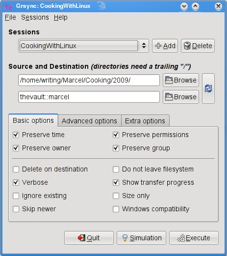
All this work at the command line is great, but there are some tools for making the process easier, particularly if you will be creating a number of rsync backups or if you want to get into more complex requirements, such as scheduled backups. A friendly graphical front end on your desktop also may be a greater incentive to perform regular backups or take a quick backup when you've added important data and a “right now” backup is desirable. The first tool I want to show you is Piero Orsoni's grsync (Figure 1).

Figure 1. grsync provides an easy-to-use interface with every rsync option you could want.

While providing a great front end to rsync, grsync also works as a teaching tool for the command-line version of the program, or at least it helps as a memory aid. Almost any command-line option available to rsync is covered in one of these three tabs: Basic options, Advanced options and Extra options. What makes it a learning tool is that if you pause over any of those check boxes with your mouse, a tooltip appears showing the command-line option with a brief description of its function.

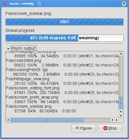
To start, click the Add button next to the session drop-down dialog and enter a name for your backup. You can define many different rsync backups here, and then launch them again at a later time. Clicking the Browse button brings up the standard Gtk2 file browser window from which you can select your local and destination folders. Unfortunately, you can't browse remote systems, but if you've already set up an rsync server, have no fear. You can enter it manually in the format I showed you earlier (for example, thevault::marcel/). When you are happy with the various options, click Execute. If you only think you are happy, click the Simulation button. (Chef Marcel loves a program with a sense of humor.) When you do click Execute, the program switches to a progress window (Figure 2), so you can see where you are in the process.

Figure 2. Once your grsync backup begins, it switches to a progress report view.

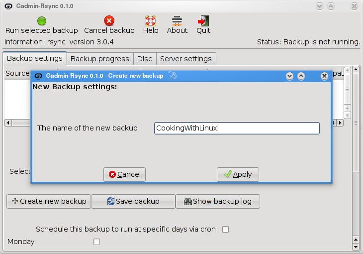
The next item on our rsync menu is Magnus Loef's GAdmin-Rsync. GAdmin-Rsync makes every aspect of creating an rsync backup a matter of filling in the blanks. What's more, the program creates backups using SSH by default, which means you can set up rsync backups to any machine to which you have secure shell access. This also means you don't actually need to have an rsync dæmon running on the remote machine if you have SSH access. Let me show you how it works.

When you start the program for the first time, you'll be asked for a name to give your new backup (Figure 3). You could back up the entire system or select specific folders of filesystems. Choose a name that makes sense to you based on what you want to back up. Enter a name, then click Apply to continue.

Figure 3. GAdmin-Rsync lets you define numerous backup configurations, each with its own identifier.

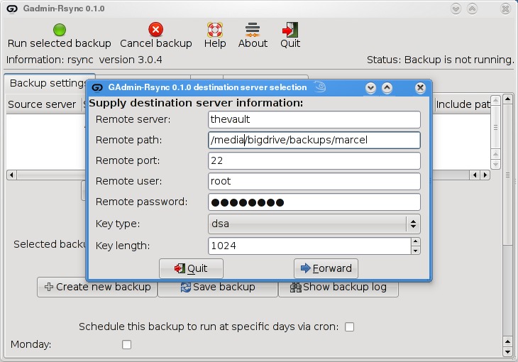
As you saw when we did this at the command line, rsync backups can be local, to a remote system or from a remote system. The next window looks for that very information (Figure 4). By default, local backup is checked. To back up to a remote server, select Local to remote backup. Because you can swap source and destination easily when using rsync, there's that third option. I routinely use a remote to local backup for my Web sites and remote systems. Click Forward to continue.

Figure 4. Your next step is to define the location of the backup.

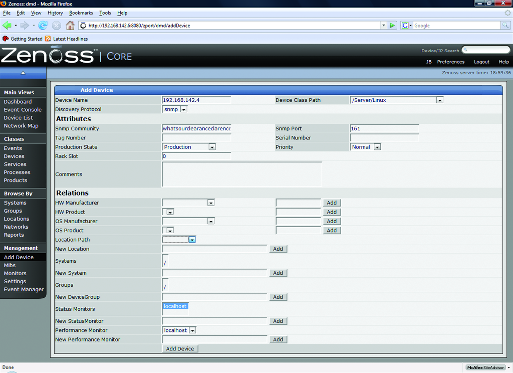
Assuming you chose to back up to your cloud, your next step is to enter the server information (Figure 5). This includes the backup path on your networked server as well as your SSH key type and length. When you have entered this information, click Forward.

Figure 5. For remote backups, GAdmin-Rsync uses SSH/SCP for secure transfers.

Now you're ready to start the rsync backup. Click the Backup Progress tab to watch all the action.

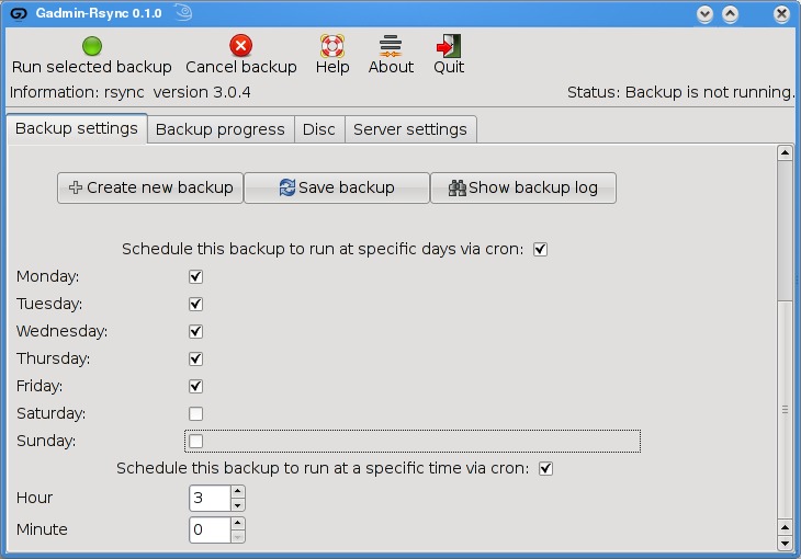
What is nice about this program is that you can (as with grsync) store a number of backup definitions, so you can choose to back up your documents, music or digital photographs when it suits you. GAdmin-Rsync goes further though. If you take a look down at the bottom of the window on the Backup settings tab, you'll notice the words “Schedule this backup to run at specific days via cron” and a check box (Figure 6). Check the box, then scroll down to choose the days you want the backup to run. A little further down, you can specify the time as well.

Figure 6. GAdmin-Rsync also provides an easy way to schedule your backups with cron.

Well, mes amis, closing time has caught up to us, and at least for now, time is one thing we can't back up. Despite the hour, I am quite sure we can convince François to refill our glasses one final time before we go our separate ways. Please, mes amis, raise your glasses and let us all drink to one another's health. A votre santé! Bon appétit!

Marcel Gagné is an award-winning writer living in Waterloo, Ontario. He is the author of the Moving to Linux series of books from Addison-Wesley. Marcel is also a pilot, a past Top-40 disc jockey, writes science fiction and fantasy, and folds a mean Origami T-Rex. He can be reached via e-mail at marcel@marcelgagne.com. You can discover lots of other things (including great Wine links) from his Web sites at www.marcelgagne.com and www.cookingwithlinux.com.


Taken From: Linux Journal Contents #180, April 2009

http://www.linuxjournal.com/article/10409

Thursday, April 9, 2009

Installing ZenOSS on Ubuntu 8.10 (Hardy Heron)

Hello previously, I have posted how to install Zenoss and setup a test environment (you can find it here), but there we instaled Zenoss in CentOS, here I'm going to show you how to install it on Ubuntu 8.10

# Install Apache With It's Documentation #####
$ sudo apt-get install apache2 apache2-doc

# Start Apache (it should already be started) #####
$ sudo /etc/init.d/apache2 start


# Test Apache #####

Type on Mozilla Firefox: http://127.0.0.1/
It souhld read: It works!


# Instaling MySQL and PHP necessary Dependencies #####

$ sudo apt-get install mysql-server mysql-client
Type in mySQL's root password in the upcoming textbox.


# Instaling SNMP Query tools #####
$ sudo apt-get install snmp


# Downloading ZenOSS #####

In http://www.zenoss.com/download/links?creg=no
you can see all the suported distributions,
you just have to pick yours if it's there,
otherwise pick the closets.

In runing Ubuntu 8.10, which isnt there so I go for
the Ubuntu 8.04, here's the link:
http://sourceforge.net/project/downloading.php?groupname=zenoss&filename=zenoss-stack-2.3.3-linux.bin&use_mirror=freefr

# Installing ZenOSS #####

$ cd /path_to_zenoss_executable_dir/

$ sudo chmod 777 zenoss-stack-2.3.3-linux.bin

$ sudo ./zenoss-stack-2.3.3-linux.bin

Type in the data the installer gui asks you, like the
database root login.


# Logging in into ZenOSS #####

After installing it should open your browser on the ZenOSS
login page, if not just type on your browser:

http://localhost:8080/

The default login and password are:

Login: admin
Password: zenoss

Now you can just continue the "Installing Net-SNMP on Linux Clients" on the previous post that you cam find here.

Monday, October 27, 2008

Change Your Mac Address in Linux

# In order to change your MAC address just type the following:

$ sudo ifconfig eth0 down hw ether 0A:0B:0C:0D:AA:BB


Note: "0A:0B:0C:0D:AA:BB" is just an example, you should put there the disired MAC address

Note: bringing down the interface (sudo ifconfig eth0 down) and them changing the mac address (sudo ifconfig eth0 hw ether 0A:0B:0C:0D:AA:BB) did not work, instead i did all in one line as shown above


# Now bring the interface back up, and you are ready to go.

$ sudo ifconfig eth0 up

Monday, August 18, 2008

Zenoss Enterprise Network Monitoring

Zenoss and the Art of Network Monitoring

August 1st, 2008 by Jeramiah Bowling in

If a server goes down, do you want to hear it?

If a tree falls in the woods and no one is there to hear it, does it make a sound? This the classic query designed to place your mind into the Zen-like state known as the silent mind. Whether or not you want to hear a tree fall, if you run a network, you probably want to hear a server when it goes down. Many organizations utilize the long-established Simple Network Management Protocol (SNMP) as a way to monitor their networks proactively and listen for things going down.

At a rudimentary level, SNMP requires only two items to work: a management server and a managed device (or devices). The management server pulls status and health information at regular intervals from the managed devices and stores the information in a table. Managed devices use local SNMP agents to notify the management server when defined behavior occurs (such as errors or “traps”), which are stored in the same table on the server. The result is an accurate, real-time reporting mechanism for outages. However, SNMP as a protocol does not stipulate how the data in these tables is to be presented and managed for the end user. That's where a promising new open-source network-monitoring software called Zenoss (pronounced Zeen-ohss) comes in.

Available for most Linux distributions, Zenoss builds on the basic operation of SNMP and uses a comprehensive interface to manage even the largest and most diverse environment. The Core version of Zenoss used in this article is freely available under the GPLv2. An Enterprise version also is available with additional features and support. In this article, we install Zenoss on a CentOS 5.1 system to observe its usefulness in a network-monitoring role. From there, we create a simulated multisystem server network using the following systems: a Fedora-based Postfix e-mail server, an Ubuntu server running Apache and a Windows server running File and Print services. To conserve space, only the CentOS installation is discussed in detail here. For the managed systems, only SNMP installation and configuration are covered.


Building the Zenoss Server

Begin by selecting your hardware. Zenoss lacks specific hardware requirements, but it relies heavily MySQL, so you can use MySQL requirements as a rough guideline. I recommend using the fastest processor available, 1GB of memory, fast enough hard disks to provide acceptable MySQL performance and Gigabit Ethernet for the network. I ran several test configurations, and this configuration seemed adequate enough for a medium-size network (100+ nodes/devices). To keep configuration simple, all firewalls and SELinux instances were disabled in the test environment. If you use firewalls in your environment, open ports 161 (SNMP), 8080 (Zenoss Management Page) and 514 (if you integrate syslog with Zenoss).

Install CentOS 5.1 on the server using your own preferences. I used a bare install with no X Window System or desktop manager. Assign a static IP address and any other pertinent network information (DNS servers and so forth). After the OS install is complete, install the following packages using the yum command below:

yum install mysql mysql-server net-snmp net-snmp-utils gmp httpd

If the mysqld or the httpd service has not started after yum installs it, start it and set it to run for your configured runlevel. Next, download the latest Zenoss Core .rpm from Sourceforge.net (2.1.3 at the time of this writing), and install it using rpm from the command line. To start all the Zenoss-related dæmons after the .rpm has been installed, type the following at a command prompt:

service zenoss start

Launch a Web browser from any machine, and type the IP address of the Zenoss server using port 8080 (for example, http://192.168.142.6:8080). Log in to the site using the default account admin with a password of zenoss. This brings up the main dashboard. The dashboard is a compartmentalized view of the state of your managed devices. If you don't like the default display, you can arrange your dashboard any way you want using the various drop-down lists on the portlets (windows). I recommend setting the Production States portlet to display Production, so we can see our test systems after they are added.

Almost everything related to managed devices in Zenoss revolves around classes. With classes, you can create an infinite number of systems, processes or service classifications to monitor. To begin adding devices, we need to set our SNMP community strings at the top-level /Devices class. SNMP community strings are like passphrases used to authenticate traffic between devices. If one device wants to communicate with another, they must have matching community names/strings. In many deployments, administrators use the default community name of public (and/or private), which creates a security risk. I recommend changing these strings and making them into a short phrase. You can add numbers and characters to make the community name more complex to guess/crack, but I find phrases easier to remember.

Click on the Devices link on the navigation menu on the left, so that /Devices is listed near the top of the page. Click on the zProperties tab and scroll down. Enter an SNMP community string in the zSNMPCommunitiy field. For our test environment, I used the string whatsourclearanceclarence. You can use different strings with different subclasses of systems or individual systems, but by setting it at the /Devices class, it will be used for any subclasses unless it is overridden. You also could list multiple strings in the zSNMPCommunities under the /Devices class, which allows you to define multiple strings for the discovery process discussed later. Make sure your community string (zSNMPCommunity) is in this list.

Installing Net-SNMP on Linux Clients

Now, let's set up our Linux systems so they can talk to the Zenoss server. After installing and configuring the operating systems on our other Linux servers, install the Net-SNMP package on each using the following command on the Ubuntu server:

sudo apt-get install snmpd

And, on the Fedora server use:

yum install net-snmp

Once the Net-SNMP packages are installed, edit out any other lines in the Access Control sections at the beginning of the /etc/snmp/snmpd.conf, and add the following lines:

##      sec.name  source      community
com2sec local localhost whatsourclearanceclarence
com2sec mynetwork 192.168.142.0/24 whatsourclearanceclarence

## group.name sec.model sec.name
group MyROGroup v1 local
group MyROGroup v1 mynetwork
group MyROGroup v2c local
group MyROGroup v2c mynetwork

## incl/excl subtree mask
view all included .1 80

## context sec.model sec.level prefix read write notif
access MyROGroup "" any noauth exact all none none

Do not edit out any lines beneath the last Access Control Sections. Please note that the above is only a mildly restrictive configuration. Consult the snmpd.conf file or the Net-SNMP documentation if you want to tighten access. On the Ubuntu server, you also may have to change the following line in the /etc/default/snmp file to allow SNMP to bind to anything other than the local loopback address:


SNMPDOPTS='-Lsd -Lf /dev/null -u snmp -I -smux -p /var/run/snmpd.pid'

Installing SNMP on Windows

On the Windows server, access the Add/Remove Programs utility from the Control Panel. Click on the Add/Remove Windows Components button on the left. Scroll down the list of Components, check off Management and Monitoring Tools, and click on the Details button. Check Simple Network Management Protocol in the list, and click OK to install. Close the Add/Remove window, and go into the Services console from Administrative Tools in the Control Panel. Find the SNMP service in the list, right-click on it, and click on Properties to bring up the service properties tabs. Click on the Traps tab, and type in the community name. In the list of Trap Destinations, add the IP address of the Zenoss server. Now, click on the Security tab, and check off the Send authentication trap box, enter the community name, and give it READ-ONLY rights. Click OK, and restart the service.

Return to the Zenoss management Web page. Click the Devices link to go into the subclass of /Devices/Servers/Windows, and on the zProperties tab, enter the name of a domain admin account and password in the zWinUser and zWinPassword fields. This account gives Zenoss access to the Windows Management Instrumentation (WMI) on your Windows systems. Make sure to click Save at the bottom of the page before navigating away.


Adding Devices into Zenoss

Now that our systems have SNMP, we can add them into Zenoss. Devices can be added individually or by scanning the network. Let's do both. To add our Ubuntu server into Zenoss, click on the Add Device link under the Management navigation section. Enter the IP address of the server and the community name. Under Device Class Path, set the selection to /Server/Linux. You could add a variety of other hardware, software and Zenoss information on this page before adding a system, but at a minimum, an IP address name and community name is required (Figure 1). Click the Add Device button, and the discovery process runs. When the results are displayed, click on the link to the new device to access it.

Figure 1. Adding a Device into Zenoss

To scan the network for devices, click the Networks link under Browse By section of the navigation menu. If your network is not in the list, add it using CIDR notation. Once added, check the box next to your network and use the drop-down arrow to click on the Select Discover Devices option. You will see a similar results page as the one from before. When complete, click on the links at the bottom of the results page to access the new devices. Any device found will be placed in the /Discovered class. Because we should have discovered the Fedora server and the Windows server, they should be moved to the /Devices/Servers/Linux and /Devices/Servers/Windows classes, respectively. This can be done from each server's Status tab by using the main drop-down list and selecting Manage→Change Class.

If all has gone well, so far we have a functional SNMP monitoring system that is able to monitor heartbeat/availability (Figure 2) and performance information (Figure 3) on our systems. You can customize other various Status and Performance Monitors to meet your needs, but here we will use the default localhost monitors.

Figure 2. The Zenoss Dashboard

Figure 3. Performance data is collected almost immediately after discovery.

Creating Users and Setting E-Mail Alerts

At this point, we can use the dashboard to monitor the managed devices, but we will be notified only if we visit the site. It would be much more helpful if we could receive alerts via e-mail. To set up e-mail alerting, we need to create a separate user account, as alerts do not work under the admin account. Click on the Setting link under the Management navigation section. Using the drop-down arrow on the menu, select Add User. Enter a user name and e-mail address when prompted. Click on the new user in the list to edit its properties. Enter a password for the new account, and assign a role of Manager. Click Save at the bottom of the page. Log out of Zenoss, and log back in with the new account. Bring the settings page back up, and enter your SMTP server information. After setting up SMTP, we need to create an Alerting Rule for our new user. Click on the Users tab, and click on the account just created in the list. From the resulting page, click on the Edit tab and enter the e-mail address to which you want alerts sent. Now, go to the Alerting Rules tab and create a new rule using the drop-down arrow. On the edit tab of the new Alerting Rule, change the Action to email, Enabled to True, and change the Severity formula to >= Warning (Figure 4). Click Save.

Figure 4. Creating an Alert Rule

The above rule sends alerts when any Production server experiences an event rated Warning or higher (Figure 5). Using a filter, you can create any number of rules and have them apply only to specific devices or groups of devices. If you want to limit your alerts by time to working hours, for example, use the Schedule tab on the Alerting Rule to define a window. If no schedule is specified (the default), the rule runs all the time. In our rule, only one user will be notified. You also can create groups of users from the Settings page, so that multiple people are alerted, or you could use a group e-mail address in your user properties.

Figure 5. Zenoss alerts are sent fresh to your mailbox.


Services and Processes

We can expand our view of the test systems by adding a process and a service for Zenoss to monitor. When we refer to a process in Zenoss, we mean an active program, usually a dæmon, running on a managed device. Zenoss uses regular expressions to monitor processes.

To monitor Postfix on the mail server, first, let's define it as a process. Navigate to the Processes page under the Classes section of the navigation menu. Use the drop-down arrow next to OS Processes, and click Add Process. Enter Postfix as the process ID. When you return to the previous page, click on the link to the new process. On the edit tab of the process, enter master in the Regex field. Click Save before navigating away. Go to the zProperties tab of the process, and make sure the zMonitor field is set to True. Click Save again. Navigate back to the mail server from the dashboard, and on the OS tab, use the topmost menu's drop-down arrow to select Add→Add OSProcess. After the process has been added, we will be alerted if the Postfix process degrades or fails. While still on the OS tab of the server, place a check mark next to the new Postifx process, and from the OS Processes drop-down menu, select Lock OSProcess. On the next set of options, select Lock from deletion. This protects the process from being overwritten if Zenoss remodels the server.

Services in Zenoss are defined by active network ports instead of running dæmons. There are a plethora of services built in to the software, and you can define your own if you want to. The built-in services are broken down into two categories: IPServices and WinServices. IPservices use any port from 1-65535 and include common network apps/protocols, such as SMTP (Port 25), DNS (53) and HTTP (80). WinServices are intended for specific use with Windows servers (Figure 6).

Figure 6. Zenoss comes with a plethora of predefined Windows services to monitor.

Adding a service is much simpler than adding a process, because there are so many predefined in Zenoss. To monitor the HTTP service on our Web server, navigate to the server from the dashboard. Use the main menu's drop-down arrow on the server's OS tab arrow, and select Add→Add IPService. Type HTTP in the Service Class Field. Notice that the field begins to prefill with matches as you type the letters. Select TCP as the protocol, and click OK. Click Save on the resulting page. As with the OSProcess procedure, return to the OS tab of the server and lock the new IPService. Zenoss is now monitoring HTTP availability on the server (Figure 7).

Figure 7. Monitoring HTTP as an IPService


Only the Beginning

There are a multitude of other features in Zenoss that space here prevents covering, including Network Maps (Figure 8), a Google Maps API for multilocation monitoring (Figure 9) and Zenpacks that provide additional monitoring and performance-capturing capabilities for common applications.

Figure 8. Zenoss automatically maps your network for you.

Figure 9. Multiple sites can be monitored geographically with the Google Maps API.

In the span of this article, we have deployed an enterprise-grade monitoring solution with relative ease. Although it's surprisingly easy to deploy, Zenoss also possesses a deep feature set. It easily rivals, if not surpasses, commercial competitors in the same product space. It is easy to manage, highly customizable and supported by a vibrant community.

Although you may not achieve the silent mind as long as you work with networks, with Zenoss, at least you will be able to sleep at night knowing you will hear things when they go down. Hopefully, they won't be trees.

Jeramiah Bowling has been a systems administrator and network engineer for more than ten years. He works for a regional accounting and auditing firm in Hunt Valley, Maryland, and holds numerous industry certifications, including the CISSP. Your comments are welcome at jb50c@yahoo.com.


Taken From: Linux Journal Issue #172/August 2008 - Zenoss and the Art of Enterprise Monitoring by Jeramiah Bowling


Wednesday, July 2, 2008

Booting Thin Clients - Over a Wireless Bridge

Thin Clients Booting over a Wireless Bridge

May 1st, 2008 by Ronan Skehill, Alan Dunne and John Nelson

How quickly can thin clients boot over a wireless bridge, and how far apart can they really be?

In the 1970s and 1980s, the ubiquitous model of corporate and academic computing was that of many users logging in remotely to a single server to use a sliver of its precious processing time. With the cost of semiconductors holding fast to Moore's Law in the subsequent decades, however, the next advances in computing saw desktop computing become the standard as it became more affordable.

Although the technology behind thin clients is not revolutionary, their popularity has been on the increase recently. For many institutions that rely on older, donated hardware, thin-client networks are the only feasible way to provide users with access to relatively new software. Their use also has flourished in the corporate context. Thin-client networks provide cost-savings, ease network administration and pose fewer security implications when the time comes to dispose of them. Several computer manufacturers have leaped to stake their claim on this expanding market: Dell and HP Compaq, among others, now offer thin-client solutions to business clients.

And, of course, thin clients have a large following of hobbyists and enthusiasts, who have used their size and flexibility to great effect in countless home-brew projects. Software projects, such as the Etherboot Project and the Linux Terminal Server Project, have large and active communities and provide excellent support to those looking to experiment with diskless workstations.

Connecting the thin clients to a server always has been done using Ethernet; however, things are changing. Wireless technologies, such as Wi-Fi (IEEE 802.11), have evolved tremendously and now can start to provide an alternative means of connecting clients to servers. Furthermore, wireless equipment enjoys world-wide acceptance, and compatible products are readily available and very cheap.

In this article, we give a short description of the setup of a thin-client network, as well as some of the tools we found to be useful in its operation and administration. We also describe a test scenario we set up, involving a thin-client network that spanned a wireless bridge.

What Is a Thin Client?

A thin client is a computer with no local hard drive, which loads its operating system at boot time from a boot server. It is designed to process data independently, but relies solely on its server for administration, applications and non-volatile storage.

Figure 1. LTSP Traffic Profile and Boot Sequence

Following the client's BIOS sequence, most machines with network-boot capability will initiate a Preboot EXecution Environment (PXE), which will pass system control to the local network adapter. Figure 1 illustrates the traffic profile of the boot process and the various different stages, which are numbered 1 to 5. The network card broadcasts a DHCPDISCOVER packet with special flags set, indicating that the sender is trying to locate a valid boot server. A local PXE server will reply with a list of valid boot servers. The client then chooses a server, requests the name of the Linux kernel file from the server and initiates its transfer using Trivial File Transfer Protocol (TFTP; stage 1). The client then loads and executes the Linux kernel as normal (stage 2). A custom init program is then run, which searches for a network card and uses DHCP to identify itself on the network. Using Sun Microsystems' Network File System (NFS), the thin client then mounts a directory tree located on the PXE server as its own root filesystem (stage 3). Once the client has a non-volatile root filesystem, it continues to load the rest of its operating system environment (stage 4)—for example, it can mount a local filesystem and create a ramdisk to store local copies of temporary files. The fifth stage in the boot process is the initiation of the X Window System. This transfers the keystrokes from the thin client to the server to be processed. The server in return sends the graphical output to be displayed by the user interface system (usually KDE or GNOME) on the thin client.

The X Display Manager Control Protocol (XDMCP) provides a layer of abstraction between the hardware in a system and the output shown to the user. This allows the user to be physically removed from the hardware by, in this case, a Local Area Network. When the X Window System is run on the thin client, it contacts the PXE server. This means the user logs in to the thin client to get a session on the server.

In conventional fat-client environments, if a client opens a large file from a network server, it must be transferred to the client over the network. If the client saves the file, the file must be again transmitted over the network. In the case of wireless networks, where bandwidth is limited, fat client networks are highly inefficient. On the other hand, with a thin-client network, if the user modifies the large file, only mouse movement, keystrokes and screen updates are transmitted to and from the thin client. This is a highly efficient means, and other examples, such as ICA or NX, can consume as little as 5kbps bandwidth. This level of traffic is suitable for transmitting over wireless links.

How to Set Up a Thin-Client Network with a Wireless Bridge

One of the requirements for a thin client is that it has a PXE-bootable system. Normally, PXE is part of your network card BIOS, but if your card doesn't support it, you can get an ISO image of Etherboot with PXE support from ROM-o-matic (see Resources). Looking at the server with, for example, ten clients, it should have plenty of hard disk space (100GB), plenty of RAM (at least 1GB) and a modern CPU (such as an AMD64 3200).

The following is a five-step how-to guide on setting up an Edubuntu thin-client network over a fixed network.

1. Prepare the server.

In our network, we used the standard standalone configuration. From the command line:

sudo apt-get install ltsp-server-standalone

You may need to edit /etc/ltsp/dhcpd.conf if you change the default IP range for the clients. By default, it's configured for a server at 192.168.0.1 serving PXE clients.

Our network wasn't behind a firewall, but if yours is, you need to open TFTP, NFS and DHCP. To do this, edit /etc/hosts.allow, and limit access for portmap, rpc.mountd, rpc.statd and in.tftpd to the local network:

portmap: 192.168.0.0/24
rpc.mountd: 192.168.0.0/24
rpc.statd: 192.168.0.0/24
in.tftpd: 192.168.0.0/24

Restart all the services by executing the following commands:

sudo invoke-rc.d nfs-kernel-server restart
sudo invoke-rc.d nfs-common restart
sudo invoke-rc.d portmap restart

2. Build the client's runtime environment.

While connected to the Internet, issue the command:

sudo ltsp-build-client

If you're not connected to the Internet and have Edubuntu on CD, use:

sudo ltsp-build-client --mirror file:///cdrom

Remember to copy sources.list from the server into the chroot.

3. Configure your SSH keys.

To configure your SSH server and keys, do the following:

sudo apt-get install openssh-server
sudo ltsp-update-sshkeys

4. Start DHCP.

You should now be ready to start your DHCP server:

sudo invoke-rc.d dhcp3-server start

If all is going well, you should be ready to start your thin client.

5. Boot the thin client.

Make sure the client is connected to the same network as your server.

Power on the client, and if all goes well, you should see a nice XDMCP graphical login dialog.

Once the thin-client network was up and running correctly, we added a wireless bridge into our network. In our network, a number of thin clients are located on a single hub, which is separated from the boot server by an IEEE 802.11 wireless bridge. It's not an unrealistic scenario; a situation such as this may arise in a corporate setting or university. For example, if a group of thin clients is located in a different or temporary building that does not have access to the main network, a simple and elegant solution would be to have a wireless link between the clients and the server. Here is a mini-guide in getting the bridge running so that the clients can boot over the bridge:

  • Connect the server to the LAN port of the access point. Using this LAN connection, access the Web configuration interface of the access point, and configure it to broadcast an SSID on a unique channel. Ensure that it is in Infrastructure mode (not ad hoc mode). Save these settings and disconnect the server from the access point, leaving it powered on.

  • Now, connect the server to the wireless node. Using its Web interface, connect to the wireless network advertised by the access point. Again, make sure the node connects to the access point in Infrastructure mode.

  • Finally, connect the thin client to the access point. If there are several thin clients connected to a single hub, connect the access point to this hub.

We found ad hoc mode unsuitable for two reasons. First, most wireless devices limit ad hoc connection speeds to 11Mbps, which would put the network under severe strain to boot even one client. Second, while in ad hoc mode, the wireless nodes we were using would assume the Media Access Control (MAC) address of the computer that last accessed its Web interface (using Ethernet) as its own Wireless LAN MAC. This made the nodes suitable for connecting a single computer to a wireless network, but not for bridging traffic destined to more than one machine. This detail was found only after much sleuthing and led to a range of sporadic and often unreproducible errors in our system.

The wireless devices will form an Open Systems Interconnection (OSI) layer 2 bridge between the server and the thin clients. In other words, all packets received by the wireless devices on their Ethernet interfaces will be forwarded over the wireless network and retransmitted on the Ethernet adapter of the other wireless device. The bridge is transparent to both the clients and the server; neither has any knowledge that the bridge is in place.

For administration of the thin clients and network, we used the Webmin program. Webmin comprises a Web front end and a number of CGI scripts, which directly update system configuration files. As it is Web-based, administration can be performed from any part of the network by simply using a Web browser to log in to the server. The graphical interface greatly simplifies tasks, such as adding and removing thin clients from the network or changing the location of the image file to be transferred at boot time. The alternative is to edit several configuration files by hand and restart all dæmon programs manually.

Evaluating the Performance of a Thin-Client Network

The boot process of a thin client is network-intensive, but once the operating system has been transferred, there is little traffic between the client and the server. As the time required to boot a thin client is a good indicator of the overall usability of the network, this is the metric we used in all our tests.

Our testbed consisted of a 3GHz Pentium 4 with 1GB of RAM as the PXE server. We chose Edubuntu 5.10 for our server, as this (and all newer versions of Edubuntu) come with LTSP included. We used six identical thin clients: 500MHz Pentium III machines with 512MB of RAM—plenty of processing power for our purposes.

Figure 2. Six thin clients are connected to a hub, and in turn, this is connected to wireless bridge device. On the other side of the bridge is the server. Both wireless devices are placed in the Azimuth chamber.

When performing our tests, it was important that the results obtained were free from any external influence. A large part of this was making sure that the wireless bridge was not affected by any other wireless networks, cordless phones operating at 2.4GHz, microwaves or any other sources of Radio Frequency (RF) interference. To this end, we used the Azimuth 301w Test Chamber to house the wireless devices (see Resources). This ensures that any variations in boot times are caused by random variables within the system itself.

The Azimuth is a test platform for system-level testing of 802.11 wireless networks. It holds two wireless devices (in our case, the devices making up our bridge) in separate chambers and provides an artificial medium between them, creating complete isolation from the external RF environment. The Azimuth can attenuate the medium between the wireless devices and can convert the attenuation in decibels to an approximate distance between them. This gives us the repeatability, which is a rare thing in wireless LAN evaluation. A graphic representation of our testbed is shown in Figure 2.

We tested the thin-client network extensively in three different scenarios: first, when multiple clients are booting simultaneously over the network; second, booting a single thin client over the network at varying distances, which are simulated by altering the attenuation introduced by the chamber; and third, booting a single client when there is heavy background network traffic between the server and the other clients on the network.

Figure 3. A Boot Time Comparison of Fixed and Wireless Networks with an Increasing Number of Thin Clients

Figure 4. The Effect of the Bridge Length on Thin-Client Boot Time

Figure 5. Boot Time in the Presence of Background Traffic

Conclusion

As shown in Figure 3, a wired network is much more suitable for a thin-client network. The main limiting factor in using an 802.11g network is its lack of available bandwidth. Offering a maximum data rate of 54Mbps (and actual transfer speeds at less than half that), even an aging 100Mbps Ethernet easily outstrips 802.11g. When using an 802.11g bridge in a network such as this one, it is best to bear in mind its limitations. If your network contains multiple clients, try to stagger their boot procedures if possible.

Second, as shown in Figure 4, keep the bridge length to a minimum. With 802.11g technology, after a length of 25 meters, the boot time for a single client increases sharply, soon hitting the three-minute mark. Finally, our test shows, as illustrated in Figure 5, heavy background traffic (generated either by other clients booting or by external sources) also has a major influence on the clients' boot processes in a wireless environment. As the background traffic reaches 25% of our maximum throughput, the boot times begin to soar. Having pointed out the limitations with 802.11g, 802.11n is on the horizon, and it can offer data rates of 540Mbps, which means these limitations could soon cease to be an issue.

In the meantime, we can recommend a couple ways to speed up the boot process. First, strip out the unneeded services from the thin clients. Second, fix the delay of NFS mounting in klibc, and also try to start LDM as early as possible in the boot process, which means running it as the first service in rc2.d. If you do not need system logs, you can remove syslogd completely from the thin-client startup. Finally, it's worth remembering that after a client has fully booted, it requires very little bandwidth, and current wireless technology is more than capable of supporting a network of thin clients.

Acknowledgement

This work was supported by the National Communications Network Research Centre, a Science Foundation Ireland Project, under Grant 03/IN3/1396.

Ronan Skehill works for the Wireless Access Research Centre at the University of Limerick, Ireland, as a Senior Researcher. The Centre focuses on everything wireless-related and has been growing steadily since its inception in 1999.

Alan Dunne conducted his final-year project with the Centre under the supervision of John Nelson. He graduated in 2007 with a degree in Computer Engineering and now works with Ericsson Ireland as a Network Integration Engineer.

John Nelson is a senior lecturer in the Department of Electronic and Computer Engineering at the University of Limerick. His interests include mobile and wireless communications, software engineering and ambient assisted living.


Taken From: Linux Journal, nº 170 2008 - Thin Clients Booting over a Wireless Bridge, by Kyle Ronan Skehill, Alen Dunne and John Nelson