Thursday, February 20, 2014

Huawei Switches Crash Course

Serial Connection
- Connect the Roll Over cable to the console port (RS232)
 
- Open Putty / Hiperterminal

- Configure the serial connection with following parameters:
    - Bits per Second: 9600
    - Parity: None
    - Stop Bits: 1
    - Flow Control: None

Clear Configuration (if the equipment is used)

- Connect the rollover cable to the console port

- Remove the power cable

- Reconnect the power cable
 
<Quidway>

Starting......

*******************************************
*                                         *
*   Quidway S3026G BOOTROM, Version 160   *
*                                         *
*******************************************

Copyright(C) 2000-2004 by HUAWEI TECHNOLOGIES CO.,LTD.
Creation Date   : Nov 03 2004, 18:41:59
CPU Type        : MIPS
CPU Clock Speed : 150MHz
Memory Size     : 64MB

Initialize LS66LTSU.......................OK!
SDRAM selftest............................OK!
FLASH selftest............................OK!
CPLD selftest.............................OK!
Switch chip selftest......................OK!
Switch SDRAM selftest.....................OK!
PHY selftest..............................OK!
Please check port leds..............finished!

The switch Mac is: 00E0-FC72-1912


Press Ctrl-B to enter Boot Menu...  0
Password:

             BOOT  MENU

1. Download application file to flash
2. Select application file to boot
3. Display all files in flash
4. Delete file from flash
5. Modify bootrom password
0. Reboot

Enter your choice(0-5): 4


No.    File Name                           
=================================================
1 *    S3026EFGTC-PWR-VRP310-r0036-32-a.bin
2      wnm2.2.2-0004.zip
3      snmpboots
4      vrpcfg.txt
Free space: 3938304 bytes
The current application file is S3026EFGTC-PWR-VRP310-r0036-32-a.bin

Please input the file number to delete: 4

Show the Running Config
display current-configuration

Show the Startup Config
display saved-configuration

Show the Startup Config
display current-configuration

Global Configuration Mode (Privileged Mode)
system-view

Undo Config. Commands
undo xxxxxx    ! equivalent to "no" in cisco

Change Hostname
sysname Huawei

Disable Spanning Tree (does not play well with cisco)
stp disable

Show a Vlan(s)
display vlan 1    ! show a vlan
display vlan       ! show vlans

Management Interface and Default Gateway
interface vlan-interface 1        ! managment vlan
ip address 1.1.1.1 255.0.0.0    ! management ip
undo shutdown                      ! activate the interface
ip route-static 0.0.0.0 0.0.0.0 129.102.0.2    ! default gateway

display ip routing-table          ! verify the default route

System View Password
password simple 20030422    ! plain text password
or
password cipher 20030422    ! encripted password

undo password                     ! remove password

Console Password
user-interface aux 0    
authentication-mode password
user privilege level 3

By default, ping, tracert, and telnet are
at visit level (0); display and debugging are
at monitoring level (1); all the configuration
commands are at configuration level (2);
and FTP, XMODEM, TFTP and commands for file
system operations are at management level (3).


set authentication password simple <password> ! plain text password
or
set authentication password cipher <password>  ! encrypted password

display user-interface    ! validate the password authentication

Telnet/SSH Password
user-interface vty 0 4
authentication-mode password
user privilege level 3

By default, ping, tracert, and telnet are
at visit level (0); display and debugging are
at monitoring level (1); all the configuration
commands are at configuration level (2);
and FTP, XMODEM, TFTP and commands for file
system operations are at management level (3).


set authentication password simple <password> ! plain text password
or
set authentication password cipher <password> ! encrypted password

display user-interface    ! validate the password authentication

Configure a Vlan on an Acess Port (unttaged)
interface Ethernet 0/1
  port access vlan

Configure a Vlan on an Range of Acess Ports (unttaged)
vlan 20                                             ! add vlan to the vlan DB
  port Ethernet 0/1 to Ethernet 0/23   ! range of access ports to add to the vlan

 
the switch automatically does the following:
<..>
interface Ethernet0/1
  port access vlan 10    ! configure a vlan on an access port
...
interface Ethernet0/23
  port access vlan 10    ! configure a vlan on an access port
<..>

Configure a Trunk Port (tagged)

interface Ethernet 0/24
  port link-type trunk                 ! define the port as trunk
  port trunk permit vlan all          ! permit all vlans
  description *** Uplink IF ***   ! port description

Save the Running Config

save

This will save the configuration in the flash memory.
The switch configurations will be written to flash.
Are you sure?[Y/N]
Now saving current configuration to flash memory.
Please wait for a while...
Save current configuration to flash memory successfully

LABNARIO - An AWSOME page with lots of tutorials about Huawei Networking is labnario, you should really check it out:

Cisco to Huawei Mapping 
Base:
http://lifeoflogs.blogspot.pt/2011/04/cisco-vs-huawei-essential-command.html

CISCO                                --> HUAWEI

ping                              --> ping
traceroute                     --> tracert
show                            --> display
show interfaces              --> display interface
Show ip route                 --> display routing-table
show ip interface            --> display ip interface
show version                  --> display version
show ip bgp                   --> display bgp routing-table
show clock                     --> display clock
show port                      --> display port-mapping
show flash                     --> dir flash: (on user view mode)
show logging                  --> display logbuffer
show snmp                    --> display snmp-agent statistics
show frame-relay pvc      --> display fr pvc-info
show users                    --> display users
show terminal length       --> screen-length disable
                                        undo screen-length disable
enable                          --> super
disable                          --> super 0 (number is privilege level from 0 to 3, where 3 is default and equivalent to “enable” on Cisco)
conf t                           --> system-view
exit                              --> quit
end                              --> return
show policy-map interface --> display qos policy interface
send -                           --> send (on user view mode)
show running-config         --> display current-configuration
show startup-config         --> display saved-configuration
write erase                     --> reset saved-configuration
write mem                      --> save
clear counters                --> reset (on user view mode)    
clear interface                --> reset counters interface
telnet                           --> telnet
enable secret                 --> Super pass cipher (system mode)
clock                            --> clock
no                                --> undo
debug / no debug            --> debugging / undo debugging
copy running-config         --> Save safely
terminal monitor              --> terminal monitor
terminal length                --> screen-length disable
                                         undo screen-length disable
terminal no monitor          --> undo terminal monitor
clear counters                -->    reset counters interface
clear interface                -->    reset counters interface
clear crypto                   -->    ipsec sa
                                            ike sa
clear access-list counters -->    reset acl counter all
reload                           -->    reboot
shutdown                      -->    shutdown
boot                             -->    boot bootrom
Aaa                              -->    hwtacacs scheme
tacacs-server                -->    hwtacacs scheme
snmp-server                  -->    tftp-server (in conf command)
router bgp                     -->    bgp
Router rip                      -->    rip
clear ip cef                    -->    reset ip fast-forwarding
clear ip route *              -->   reset ip routing-table statistics protocol all
Clear ip bgp                   -->    reset bgp all
Show tech                    -->    display diagnostic-information
Sh ip nat translation       -->    display nat session
Show Controller             -->    display controller
show dsl int atm 0         -->    display dsl status interface Atm 2/0
show atm pvc                -->    display atm pvc-info
debug pvc nego             -->    debug atm all
sho crypto isakmp sa      -->    display ike sa
sho crypto isakmp key     -->    display ike peer
sho crypto isakmp police  -->    display ike proposal
Sunday, February 16, 2014

Fix ‘File Path Too Long’ Error – Windows

How to Fix ‘File Path Too Long’ Error While Copying, Deleting or Opening Files, Without Using Third Party Applications

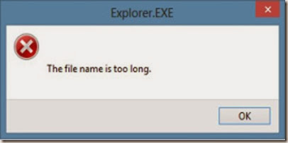
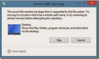
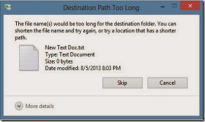
This is an error you might have experienced more at work than at home. You decided to copy a file or take a backup of it to another location or drive, you browse to the source location and starts copying. But you get this error, instead.

clip_image002 clip_image003

clip_image004

Why does it come?

There is a pre-defined character limit beyond which you cannot name a file or folder, and it varies from one OS to another. Mostly it varies between 256 and 260 characters. This is the character limit for a file name, which excludes the file path under which it is located, like “C:\Documents and Settings\Test User\Desktop\test file.txt”. But, when you copy a file from one location, it takes into account the entire file path. So, if the file is residing under a folder which is too deep or too long, that has a length beyond the set-limit, you will get errors like the ones shown above.

How do I know that the file path length is causing the issue?

  • One way you will know is definitely from the error messages similar to the ones above which clearly mentions the problem.
  • Some other times, it won’t. You will simply get a message saying ‘Cannot Copy’ in the title.
  • Or, some other times, the files won’t open properly. They would open and close instantly without giving any errors.
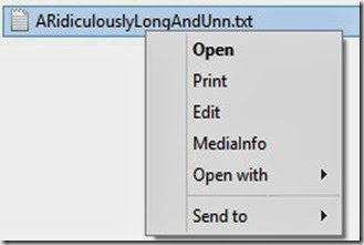
  • Also when you right-click such files, the number of options available in the right-click menu would also be limited compared to other files.

clip_image005

All these are caused by those incredibly long file paths.

So, how can I copy the files or fix this issue?

There are a couple of ways you can fix this easily without the use of any 3rd party applications.

  1. Check the folder path, and shorten some of the folder names in between thereby reducing the file path length. You don’t necessarily need to put the folder name as ‘Mission Impossible Three’ when you can still recognize it as ‘MI 3.’
  2. The main thing many people miss when they save a file or folder their Desktop is that the actual path to that folder in desktop is either ‘C:\Documents and Settings\%username%\Desktop’ or ‘C:\Users\%username%\Desktop’ depending on your OS. So as you can see, its already longer than you thought it is. Go to Start — Run and type ‘cmd‘ and press OK, or click start/press windows key and type ‘Command Prompt‘. Once in the command prompt window, type the following command :

subst V: “C:\TheRidiculouslyLongFolderName

WhichYouDontNeedAtAll” ,

where

subst = substitute command

V = a drive letter of my choice, you can select your own.

C:\TheRidiculouslyLongFolderNameWhichYouDontNeedAtAll = the file path you want to shorten. Change it according to your situation.

clip_image006

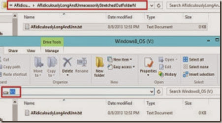
So, basically this command would convert the entire folder path you provide in the command, into a single temporary drive letter, like V in this case, which gets created in My Computer. Now all you need to do is, go to the My Computer, and open the V drive, and copy the data from there.

clip_image007

Note : To remove the new drive from My Computer, go to Command Prompt again and type subst V: /d

There you have it, try this the next time you get the error, and see how it goes. If you are still confused, let me know in the comments section below.

Taken From: http://vimalsuresh.com/2013/08/08/how-to-fix-file-path-too-long-error-while-copying-deleting-or-opening-files-without-using-third-party-applications/

More Details on “subst”, can be found at:

Tuesday, February 11, 2014

Beginner’s Guide to IPTables (Linux Firewall)

The Beginner’s Guide to iptables, the Linux Firewall

clip_image002

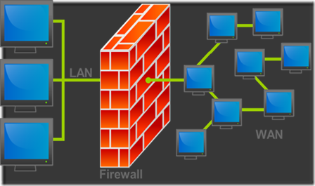
Iptables is an extremely flexible firewall utility built for Linux operating systems. Whether you’re a novice Linux geek or a system administrator, there’s probably some way that iptables can be a great use to you. Read on as we show you how to configure the most versatile Linux firewall.

About iptables

iptables is a command-line firewall utility that uses policy chains to allow or block traffic. When a connection tries to establish itself on your system, iptables looks for a rule in its list to match it to. If it doesn’t find one, it resorts to the default action.

iptables almost always comes pre-installed on any Linux distribution. To update/install it, just retrieve the iptables package:

sudo apt-get install iptables

There are GUI alternatives to iptables like Firestarter, but iptables isn’t really that hard once you have a few commands down. You want to be extremely careful when configuring iptables rules, particularly if you’re SSH’d into a server, because one wrong command can permanently lock you out until it’s manually fixed at the physical machine.

Types of Chains

iptables uses three different chains: input, forward, and output.

Input – This chain is used to control the behavior for incoming connections. For example, if a user attempts to SSH into your PC/server, iptables will attempt to match the IP address and port to a rule in the input chain.

Forward – This chain is used for incoming connections that aren’t actually being delivered locally. Think of a router – data is always being sent to it but rarely actually destined for the router itself; the data is just forwarded to its target. Unless you’re doing some kind of routing, NATing, or something else on your system that requires forwarding, you won’t even use this chain.

There’s one sure-fire way to check whether or not your system uses/needs the forward chain.

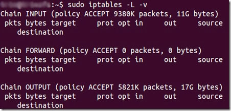
iptables -L -v

clip_image003

The screenshot above is of a server that’s been running for a few weeks and has no restrictions on incoming or outgoing connections. As you can see, the input chain has processed 11GB of packets and the output chain has processed 17GB. The forward chain, on the other hand, has not needed to process a single packet. This is because the server isn’t doing any kind of forwarding or being used as a pass-through device.

Output – This chain is used for outgoing connections. For example, if you try to ping howtogeek.com, iptables will check its output chain to see what the rules are regarding ping and howtogeek.com before making a decision to allow or deny the connection attempt.

The caveat

Even though pinging an external host seems like something that would only need to traverse the output chain, keep in mind that to return the data, the input chain will be used as well. When using iptables to lock down your system, remember that a lot of protocols will require two-way communication, so both the input and output chains will need to be configured properly. SSH is a common protocol that people forget to allow on both chains.

Policy Chain Default Behavior

Before going in and configuring specific rules, you’ll want to decide what you want the default behavior of the three chains to be. In other words, what do you want iptables to do if the connection doesn’t match any existing rules?

To see what your policy chains are currently configured to do with unmatched traffic, run theiptables -L command.

clip_image004

As you can see, we also used the grep command to give us cleaner output. In that screenshot, our chains are currently figured to accept traffic.

More times than not, you’ll want your system to accept connections by default. Unless you’ve changed the policy chain rules previously, this setting should already be configured. Either way, here’s the command to accept connections by default:

iptables --policy INPUT ACCEPT
iptables --policy OUTPUT ACCEPT
iptables --policy FORWARD ACCEPT

By defaulting to the accept rule, you can then use iptables to deny specific IP addresses or port numbers, while continuing to accept all other connections. We’ll get to those commands in a minute.

If you would rather deny all connections and manually specify which ones you want to allow to connect, you should change the default policy of your chains to drop. Doing this would probably only be useful for servers that contain sensitive information and only ever have the same IP addresses connect to them.

iptables --policy INPUT DROP
iptables --policy OUTPUT DROP
iptables --policy FORWARD DROP

Connection-specific Responses

With your default chain policies configured, you can start adding rules to iptables so it knows what to do when it encounters a connection from or to a particular IP address or port. In this guide, we’re going to go over the three most basic and commonly used “responses”.

Accept – Allow the connection.

Drop – Drop the connection, act like it never happened. This is best if you don’t want the source to realize your system exists.

Reject – Don’t allow the connection, but send back an error. This is best if you don’t want a particular source to connect to your system, but you want them to know that your firewall blocked them.

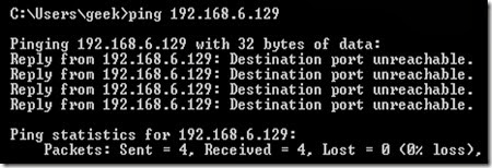
The best way to show the difference between these three rules is to show what it looks like when a PC tries to ping a Linux machine with iptables configured for each one of these settings.

Allowing the connection:

clip_image005

Dropping the connection:

clip_image006

Rejecting the connection:

clip_image007

Allowing or Blocking Specific Connections

With your policy chains configured, you can now configure iptables to allow or block specific addresses, address ranges, and ports. In these examples, we’ll set the connections to DROP, but you can switch them to ACCEPT or REJECT, depending on your needs and how you configured your policy chains.

Note: In these examples, we’re going to use iptables -A to append rules to the existing chain. iptables starts at the top of its list and goes through each rule until it finds one that it matches. If you need to insert a rule above another, you can use iptables -I [chain] [number] to specify the number it should be in the list.

Connections from a single IP address

This example shows how to block all connections from the IP address 10.10.10.10.

iptables -A INPUT -s 10.10.10.10 -j DROP

Connections from a range of IP addresses

This example shows how to block all of the IP addresses in the 10.10.10.0/24 network range. You can use a netmask or standard slash notation to specify the range of IP addresses.

iptables -A INPUT -s 10.10.10.0/24 -j DROP

or

iptables -A INPUT -s 10.10.10.0/255.255.255.0 -j DROP

Connections to a specific port

This example shows how to block SSH connections from 10.10.10.10.

iptables -A INPUT -p tcp --dport ssh -s 10.10.10.10 -j DROP

You can replace “ssh” with any protocol or port number. The -p tcp part of the code tells iptables what kind of connection the protocol uses.  If you were blocking a protocol that uses UDP rather than TCP, then -p udp would be necessary instead.

This example shows how to block SSH connections from any IP address.

iptables -A INPUT -p tcp --dport ssh -j DROP

Connection States

As we mentioned earlier, a lot of protocols are going to require two-way communication. For example, if you want to allow SSH connections to your system, the input and output chains are going to need a rule added to them. But, what if you only want SSH coming into your system to be allowed? Won’t adding a rule to the output chain also allow outgoing SSH attempts?

That’s where connection states come in, which give you the capability you’d need to allow two way communication but only allow one way connections to be established. Take a look at this example, where SSH connections FROM 10.10.10.10 are permitted, but SSH connections TO 10.10.10.10 are not. However, the system is permitted to send back information over SSH as long as the session has already been established, which makes SSH communication possible between these two hosts.

iptables -A INPUT -p tcp --dport ssh -s 10.10.10.10 -m state --state NEW,ESTABLISHED -j ACCEPT

iptables -A OUTPUT -p tcp --sport 22 -d 10.10.10.10 -m state --state ESTABLISHED -j ACCEPT

Saving Changes

The changes that you make to your iptables rules will be scrapped the next time that the iptables service gets restarted unless you execute a command to save the changes.  This command can differ depending on your distribution:

Ubuntu:

sudo /sbin/iptables-save

Red Hat / CentOS:

/sbin/service iptables save

Or

/etc/init.d/iptables save

Other Commands

List the currently configured iptables rules:

iptables -L

Adding the -v option will give you packet and byte information, and adding -n will list everything numerically. In other words – hostnames, protocols, and networks are listed as numbers.

To clear all the currently configured rules, you can issue the flush command.

iptables -F

Taken From: http://www.howtogeek.com/177621/the-beginners-guide-to-iptables-the-linux-firewall/

Friday, February 7, 2014

Sainsmart 2-Channel 5V Relay - Arduino / Raspberry Pi

Introduction

clip_image002

The Arduino Relay module allows a wide range of microcontroller such as Arduino, Raspberry Pi, AVR ,PIC, ARM with digital outputs to control larger loads and devices like AC or DC Motors, electromagnets, solenoids, and incandescent light bulbs. This module is designed to be integrated with 2 relays that it is capable of control 2 relays.The relay shield use one QIANJI JQC-3F high-quality relay with rated load 7A/240VAC,10A/125VAC,10A/28VDC.The relay output state is individually indicated by a light-emitting diode.

Features

  • Model: SRD-05VDC-SL-C
  • Number of Relays: 2
  • Control signal: TTL level
  • Rated load: 7A/240VAC 10A/125VAC 10A/28VDC
  • Contact action time: 10ms/5ms

Pin definition

clip_image004

  • COM - Common pin: This is source pin, that starts connected to NC, and connects to NO when you apply 0v / GND (active low)
  • NC (Normally Closed): in which case NC is connected with COM when INT1 is set low and disconnected when INT1 is high;
  • NO (Normally Open): in which case NO is disconnected with COM1 when INT1 is set low and connected when INT1 is high.
  • INT 1- Relay 1 control port: changes from the COM–>NO to the COM–>NC when you apply 0v / GND (active low)
  • INT 2- Relay 2 control port: changes from the COM à NO to the COM à NC when you apply 0v / GND (active low)

Video Explaination

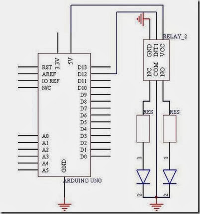
Usage with Arduino

clip_image005

Example Code

int Relay = 12;

void setup()
{
    pinMode(Relay, OUTPUT); //Set Pin12 as output
}

void loop()
{
    digitalWrite(Relay, HIGH); //Turn off relay
    delay(2000);
    digitalWrite(Relay, LOW); //Turn on relay
    delay(2000);
}

Videos

How to buy


Based On:

Tuesday, February 4, 2014

Share a VM on VMWare Workstation (aka Server Mode)

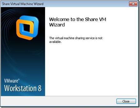
The virtual machine sharing service is not available in VMWare Workstation 8

Posted on April 16, 2012 by Ben

I wanted to share a VM, but this error message appeared when doing so:

clip_image002

The virtual machine sharing service is not available.

Solution

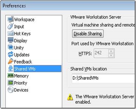
Changing the TCP Port that VMWare Workstation uses for the Shared VMs feature did the trick!

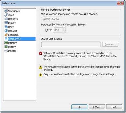
First startup VMWare Workstartion as an admin, otherwise you don’t have sufficient permissions;

clip_image004

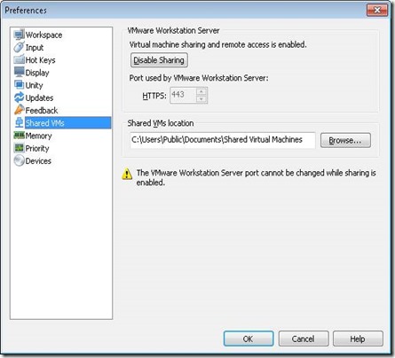
Started as administrator:

clip_image006

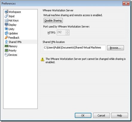
Stop the service first, by hitting the “Disable Sharing” button. Then change the port number, and start the the sharing service again. I changed it to 242;

clip_image008

Before sharing a VM, I changed the location where all shared VMs are located. Because I wanted VMs on a second SSD.

clip_image010

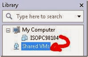
Share a VM by moving  a machine into the Shared VMs container in the Library;

clip_image012

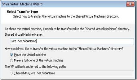
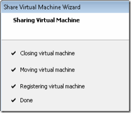
The Share VM Wizard starts. Transfer the VM to the “Shared Virtual Machines” directory (the one I changed a minute ago);

clip_image014

clip_image015

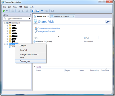
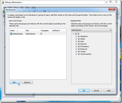
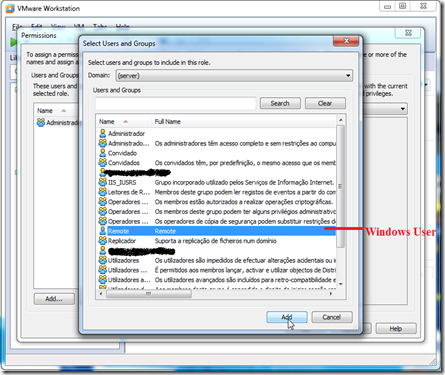
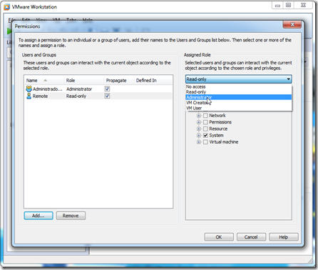
Adding a user for remote access (this is a windows user, but it can´t be you current user)

ScreenShot019

ScreenShot020

ScreenShot021

ScreenShot022

On your local firewall you must allow the following TCP Ports:

  • HTTPs: TCP port 242 (in this case)
  • MKS: TCP port 902 (without this it doesn´t display the remote VM desktop)

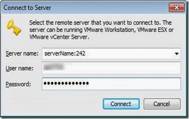
Now connect to the machine where the VM is stored using VMware Workstation 8 on another machine. But specify the port name we just changed!

clip_image017clip_image019

Maybe you have to add permissions on the remote VM server, but the above should solve the “The virtual machine sharing service is not available” issue.

ONE THOUGHT ON “THE VIRTUAL MACHINE SHARING SERVICE IS NOT AVAILABLE IN VMWARE WORKSTATION 8”

Based On: http://esense.be/33/2012/04/16/the-virtual-machine-sharing-service-is-not-available-in-vmware-workstation-8/

Multiple Remote Desktop Sessions in Windows

Enable Concurrent Desktop Sessions in Windows

clip_image001

By Jose Vilches on January 6, 2012

Professional and Ultimate editions of Windows come with a built in Remote Desktop (RDP) feature that allows you to access your machine remotely while away from home or the office. Unfortunately, it is limited by default to one concurrent user per session, meaning that if someone remotely connects to the computer, whoever was logged in at the moment will be automatically logged off, even if the user is physically at the computer.

This is not a technical limitation but rather a licensing one. Case in point, Remote Desktop in server editions of Windows by default supports two concurrent connections to remotely troubleshoot or administer a computer. More users can connect simultaneously, too, as long as the machine can handle it with the resources it has available and you have the required client access licenses for that particular server.

However, there are a few reasons why concurrent sessions would come in handy for power users not necessarily running a server. For example, if you have a dedicated Media Center PC running in the living room, you'll be able to remotely access all files on the machine without interrupting the person watching TV.

Or if you are sharing a computer with other users, concurrent Remote Desktop sessions will allow more than one person use that system under a different or even the same user account, without kicking each other off. By patching a file called termsrv.dll, located in %SystemRoot%System32, this is possible in all editions of Windows 7, Windows Vista and Windows XP.

clip_image003

Download: UniversalTermsrvPatch_20090425.zip (zip File, 66 KB, mirror #2 mirror #3)

Fortunately for us, Internet user DeepXW already did all the dirty work a while ago and posted his Universal Termsrv.dll Patchfor anyone to get their hands on. Simply download and unzip the file, then run the corresponding file as administrator (right-click the exe file and select Run as Administrator). For 32-bit systems use UniversalTermsrvPatch-x86.exe and for 64-bit versions of Windows use UniversalTermsrvPatch-x64.exe.
You should see a window like the one above where you can patch termsrv.dll to remove the Concurrent Remote Desktop sessions limit and restore the original file at any time (a backup file is located at 'windowssystem32termsrv.dll.backup'). After applying the patch, restart your system and you are ready to go.
clip_image004

To test it out simply leave a session open on to the PC where you applied the patch, then from another machine try and connect to the computer remotely. If all goes well both users will be logged on and active.
Taken From: http://www.techspot.com/guides/485-windows-concurrent-sessions/

Sunday, January 26, 2014

Share Your Internet via Wifi – Windows 8 (Tablet / Desktop)

How to Share Your 3G/4G Internet Connection With Other Devices From Your Windows Tablet

clip_image001

I’m sure that we are not the only people who carry around multiple devices and only have 1 or 2 mobile data plans. If the device carrying your data plan happens to be your Windows tablet, start celebrating. We’ll show you how you can share that data goodness with your other devices.

Note: The following method was tested and confirmed working on a Samsung ATIV Tab.

How to Share Your Internet Connection With Other Devices From Your Windows Tablet

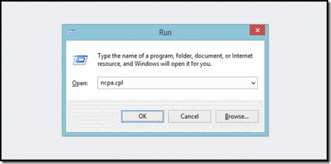
Press the Windows + R key combination to bring up a run box, type ncpa.cpl and hit enter.

clip_image003

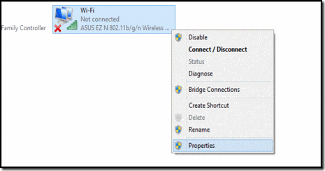
When your network connections control panel window opens, right-click on your Wireless network adapter and select properties from the context menu.

clip_image005

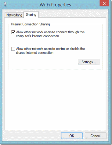
Now switch over to the Sharing tab and allow other devices to use your machine’s internet by selecting the first checkbox and then unchecking the second before clicking on the OK button.

clip_image007

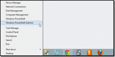
Now press the Win + X keyboard combination to bring up the WinX menu in the bottom left of your screen. From here you will need to launch an administrative command prompt, or PowerShell prompt if you happen to be running Windows 8.1.

clip_image009

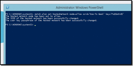
The first thing we need to do is set up the wireless network, which is done using the netsh command like so:

netsh wlan set hostednetwork mode=allow ssid=”How-To Geek” key=”Pa$$w0rd$”

Where ssid is the name of your network and key is the password you want users to connect with. It is also worth mentioning that the access point is created with WPA2-PSK (AES) encryption.

clip_image011

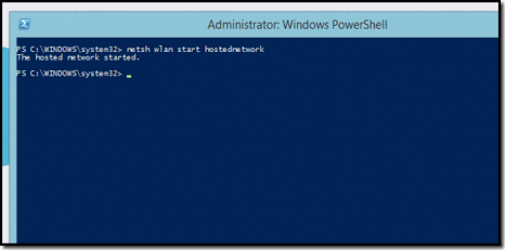
Finally we need to start broadcasting our newly created network so that our other devices can pick it up.

netsh wlan start hostednetwork

clip_image013

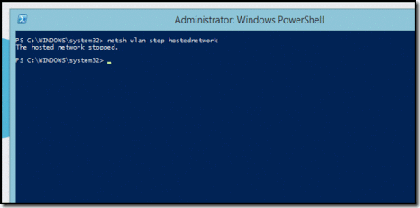
That’s all there is to it. When you are done, you can simply run the following command to stop the network.

netsh wlan stop hostednetwork

clip_image015

Taken From: http://www.howtogeek.com/167504/how-to-share-your-3g4g-internet-connection-with-other-devices-from-your-windows-tablet/