Saturday, June 6, 2015

Huawei - Switch: Local Port Mirroring (aka SPAN)

How to Configure Local Port Mirroring?

As shown in Figure 1, HostA is connected to GigabitEthernet0/0/1 on SwitchA, and Server is directly connected to GigabitEthernet0/0/2 on SwitchA.

Users want to use the monitoring device (Server) to monitor packets sent from HostA.

networking-diagram-of-local-port-mirroring

Figure 1 Networking diagram of local port mirroring

Note: e example can be applied to Huawei Switches (like Huawei S2700, Huawei S3700 switches and Quidway S5700, etc )


Configuration Roadmap

The configuration roadmap is as follows:

  1. Configure GigabitEthernet0/0/2 on SwitchA as the local observing port so that Server can receive mirrored packets.
  2. Configure GigabitEthernet0/0/1 on SwitchA as the mirrored port to monitor packets passing through the mirrored port.

Procedure

  1. Configure an observing port.

# Configure GigabitEthernet0/0/2 on SwitchA as the local observing port.

<HUAWEI> system-view
[HUAWEI] sysname SwitchA
[SwitchA] observe-port 1 interface gigabitethernet 0/0/2

  1. Configure a mirrored port.

# Configure GigabitEthernet0/0/1 on SwitchA as the mirrored port to monitor packets sent from HostA.

[SwitchA] interface gigabitethernet 0/0/1
[SwitchA-GigabitEthernet0/0/1] port-mirroring to observe-port 1 inbound
[SwitchA-GigabitEthernet0/0/1] return

  1. Verify the configurations.

# Check the observing port configuration.

<SwitchA> display observe-port

———————————————————————-
Index         : 1
Untag-packet   : No
Interface     : GigabitEthernet0/0/2
———————————————————————-


# Check the mirrored port configuration.

<SwitchA> display port-mirroring
———————————————————————-
Observe-port 1 : GigabitEthernet0/0/2
———————————————————————-
Port-mirror:
———————————————————————-
Mirror-port               Direction Observe-port
———————————————————————-
1   GigabitEthernet0/0/1     Inbound   Observe-port 1
———————————————————————-


Configuration File

# Configuration file of SwitchA

sysname SwitchA
#
observe-port 1 interface GigabitEthernet0/0/2
#
interface GigabitEthernet0/0/1
port-mirroring to observe-port 1 inbound
#
return

The more information about technical support you can consult with our engineer the e-mail address is as below:

support@huanetwork.com

Taken From: http://www.huanetwork.com/blog/how-to-configure-local-port-mirroring/

Huawei - Router: Password Recovery - BootROM (aka ROMmon)

How do I Log into the Device Using BootROM If I Forget the Console Login Password?
The console interface on RouterA connects to the PC and the console login password is forgotten. It is required that BootROM (aka ROMmon) be used to log in to the device. This example applies to V200R003C00 and later versions, and all Huawei AR routers.

clip_image001Figure 1 - Networking for login through BootROM when the console login password is forgotten

Log in to the router through the console port.

NOTE: When performing operations, ensure that users on the serial port are kept online.
Restart RouterA. Press Ctrl+B to enter the BootROM menu when the following information is displayed:

BIOS Creation Date : Nov 10 2011, 14:41:12                                   
DDR DRAM init : OK                                                           
Start Memory Test ? (‘t’ or ‘T’ is test):skip                                 
Copying Data : Done                                                           
Uncompressing : Done                                                           
USB2 Host Stack Initialized.                                                 
USB Hub Driver Initialized                                                   
USBD Wind River Systems, Inc. 562 Initialized                               
Octeon Host Controller Initialize……Done.                                 

Press Ctrl+B to break auto startup … 3   

After pressing Ctrl+B, you need to enter the password

  • Versions earlier than V200R005C00: huawei,
  • V200R005C00 and later versions: Admin@huawei

to enter the BootROM menu.


In general the default user and password are:

in new equipments or with a updated image the password is “Password2”.


Select choice 7 to enter the Password Manager menu.

Main Menu 
1. Default Startup                                                         
2. Serial Menu                                                           
3. Network Menu                                                           
4. Startup Select                                                         
5. File Manager                                                           
6. Reboot                                                                 
7. Password Manager

Enter your choice(1-6):7                                                     
Select choice 2 to delete the console login password.

PassWord Menu                                                         
1. Modify the menu password                                               
2. Clear the console login password                                       
3. Return                                                                 
Enter your choice(0-1):2

Clear the console login password Succeed!

PassWord Menu                                                         
1. Modify the menu password                                               
2. Clear the console login password                                       
3. Return
           
Enter your choice(0-1):0
Select 1 and wait for a while. Then you can log in to the device.

Main Menu                                                             
1. Default Startup                                                         
2. Serial Menu                                                           
3. Network Menu                                                           
4. Startup Select                                                         
5. File Manager                                                           
6. Reboot                                                                 
7. Password Manager

Enter your choice(1-6):1

The more information about technical support you can consult with our engineer the e-mail address is as below:

support@huanetwork.com


Taken From: http://www.huanetwork.com/blog/how-do-i-log-into-the-device-using-bootrom-if-i-forget-the-console-login-password/

Saturday, May 9, 2015

Windows 8 and The New UEFI BIOS

How To Access The BIOS On A Windows 8 Computer

clip_image001

Among the many changes coming with Windows 8 and new computers designed for it is a change in the way we access our computers’ BIOS. No longer do we press a certain key during the boot process to reveal the BIOS – instead, an option to access the BIOS is located in Windows 8’s boot options menu.

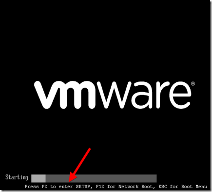
Traditionally, computers displayed a message like “Press F2 to enter setup” at the beginning of the boot process. Pressing this key entered the computer’s BIOS. However, Windows 8 hardware uses the UEFI replacement for the traditional BIOS, like Macs do. Some solid-state drive-equipped Windows 8 PCs boot so fast that you’d only have a 200 millisecond (that’s 0.2 seconds) window of opportunity to press the key combination.


Windows 8 Hardware vs. Old Computers With Windows 8

Note that this new method only applies if you purchased a new computer with Windows 8 preinstalled – these will use UEFI. However, if you’ve installed Windows 8 on an existing computer that uses the legacy BIOS system, you’ll access the BIOS in the same way as always by pressing the key that appears during your boot process.

This key is often F2 or Delete, but it can also be other keys. The exact key depends on your computer – if you don’t see the appropriate key displayed on your screen during the boot-up process, consult your computer’s manual.

clip_image002


Accessing Boot Options

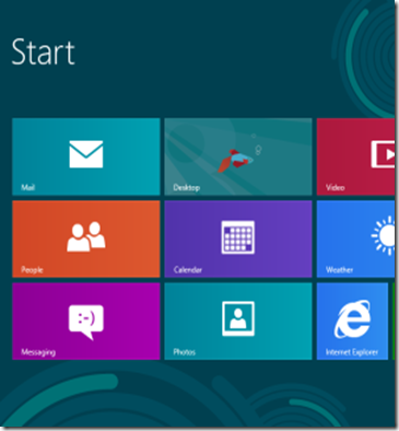
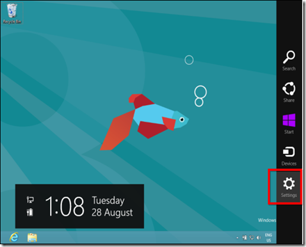
There are several ways to access Windows 8’s boot options menu. The easiest one to find is in the PC Settings application – press WinKey+C to reveal the Charms bar, click Settings, and select Change PC settings to access it.

clip_image003

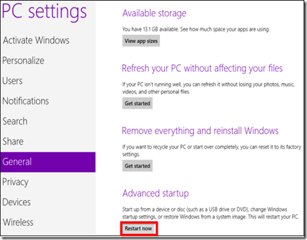
In the PC Settings application, select the General category and click the Restart now button under Advanced startup. Your computer will restart and you’ll enter the Windows 8s boot options menu, where you can access the UEFI BIOS and change other settings.

clip_image004

In more updated versions of windows 8 (like 8.1), the Advanced startup has moved:

Windows Key+C > Settings > Change PC settings > Update and recovery > Recovery > Advanced startup + Restart now

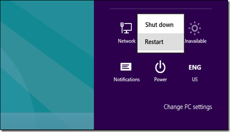
You can also hold Shift while clicking Restart in the Shut Down menu to restart your computer into the boot options menu. This is a quick way to restart into the boot options menu, as you can access the Shut Down button from the Charms anywhere on your system.

clip_image005

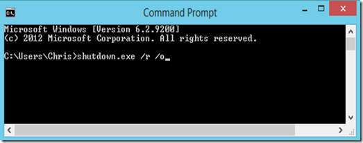
Command-line geeks will be happy to know they can run a special shutdown.exe command in a Command Prompt window to restart their computer directly into the boot options menu:

Shutdown.exe /r /o

clip_image006


Accessing UEFI BIOS

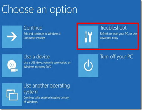
The boot options menu has been designed to integrate some commonly used options that people went into the BIOS for. For example, if you want to boot your computer off a USB drive, DVD or CD, or another device, you can click the Use a device tile in the boot options menu and select the device you want to boot from.

If you’re just here to access your computer’s UEFI BIOS, click the Troubleshoot tile.

clip_image007

This will reveal an Advanced Options screen with a variety of tools – the UEFI Firmware Settings tile will take you to your computer’s BIOS. (On UEFI, which stands for “Unified Extensible Firmware Interface”, the firmware settings menu is equivalent to a traditional PC’s BIOS.)

clip_image008

If you don’t see the UEFI Firmware Settings tile here, your computer doesn’t use UEFI. You’ll need to access the BIOS in the traditional way, by pressing a specific key during the boot-up process. See the first section above for more information.

If there’s an error booting Windows, you won’t be locked out of the BIOS — the boot options screen will appear when you start your computer. From here, you can repair Windows or enter your BIOS.


Why the Change?

While this may be slightly inconvenient, as there’s no way to access the BIOS in normal use without booting into Windows first, it’s surely necessary. Microsoft’s blog post about this on the Building Windows 8 blog describes how this new system came to be. With the increased boot speed, some systems had a less than 200 millisecond window of opportunity to press a key. Even the best key-tappers at Microsoft could only press a key once every 250ms — to access the BIOS, frantic tapping, luck, and several compuer reboots were all necessary.

This also brings some much-needed consistency to Windows 8 computers — they’ll all have a consistent way of accessing the BIOS. Currently, different computers use different keys at start-up.

While Windows 8 may have some questionable design decisions that some people will dislike, this shouldn’t be one of them. The new method of accessing the BIOS is necessary and well-implemented.

Taken From: http://www.makeuseof.com/tag/how-to-access-the-bios-on-a-windows-8-computer/ (By Chris Hoffman)

Tuesday, May 5, 2015

Cisco / Linux - Decapsulating Cisco ERSPAN With Linux

Decapsulation ERSPAN Traffic With Open Source Tools

Posted on May 3, 2015 by Radovan Brezula

Cisco Encapsulated Remote SPAN (ERSPAN) feature allows to monitor traffic on one or more ports and send the monitored traffic to one or more destination ports.  Traffic is encapsulated into GRE tunnel and routed via network to ERSPAN destination. Any device that supports ERSPAN can be used as ERSPAN destination. It might be another Cisco device or Linux with installed software that can decapsulate GRE traffic.

The goal of this article is to show methods and tools for decapsulation of  ERSPAN traffic. For this purpose I have built simple lab that consists of a Cisco CSR 1000v router and two Linux boxes. Core Linux represents a network host and generates network traffic (ICMP) that is going to be monitored. It is connected to the port GigabitEthernet1 of the Cisco router. The router is configured to monitor traffic on the port Gi1 and it sends traffic encapsulated in GRE tunneling protocol to IP address 10.230.10.1. It is the IP address of the ERSPAN destination configured on Linux  Security Union. Security Onion is a unique Linux distro for intrusion detection, network security monitoring, and log management based on Ubuntu however any other Linux distro can be used.

clip_image001

Picture 1 - ERSPAN Lab Topology

Below is an example of ERSPAN configuration on the CSR 1000v router. This is the source ERSPAN type and with configured rspan_id 1. The interface Gi1 is being monitored and the GRE traffic is sent to ERSPAN destination address IP 10.230.10.1.

CSR1000v# show running-config | b monitor
monitor session 1 type erspan-source
description ERSPAN to 10.230.10.1
source interface Gi1
destination
erspan-id 1
mtu 1464
ip address 10.230.10.1
origin ip address 10.230.10.2

Capturing ERSPAN Traffic with Wireshark

We are going to capture and analyze ERSPAN traffic with Wireshark packet sniffer. First configure IP address 10.230.10.1 on interface eth1 of the Linux Security Onion.

janosik@onion:~$ sudo su
root@onion# ip address add 10.230.10.1/24 dev eth1

Now use Wireshark to capture GRE traffic on Security Onion on its interface eth1 and ping the router IP address 192.168.1.2 from the Linux Core host (IP 192.168.1.1). If the source ERSPAN is properly configured on router, packets from the subnet 192.168.1.0/24 should appear in Wireshark output.

A closer look at the picture below reveals that the original packet ICMP packet (MAC header, IPv4 header and ICMP header) is now encapsulated as following.

MAC header + IPv4 header (10.230.10.2, 10.230.10.1) + GRE header (Protocol type ERSPAN) + ERPAN header + (original packet)

clip_image002

Picture 2 - Encapsulated GRE Traffic Captured on Interface Eth1

An original ICMP packet is encapsulated into GRE tunnel and the new outer MAC and IPv4 + GRE + ERSPAN headers are added to original packets. It allows encapsulated traffic to be forwarded through network to ERSPAN destination. However if we want software application such as IPS/IDS to analyze encapsulated packets, the outer L2 and L3 headers must be striped from packet. This can be done with tools such as RCDCAP  which dissects packets from GRE tunnel.


Configuring GRE tunnel on ERSPAN Destination Device

If for some reason we do not want to install special software that dissects packets from GRE tunnel we can configure GRE tunnel on ERSPAN destination (Linux Security Onion) and let IDS to listen on a tunneled interface. Thanks to this configuration the outer MAC and IPv4 headers are stripped and do no appear in Wireshark output.

a) Load gre module to kernel

janosik@onion:~$ sudo su
root@onion# modprobe ip_gre

b) Choose receiving interface and assign IPv4 to it

root@onion# ip addr add 10.230.10.1/24 dev eth1

Set the MTU of the network interface that receives GRE packets larger than 1500 e.g. to 1900.  Otherwise we are going to miss some bytes in larger packets.

root@onion# ip link set dev eth1 mtu 1900

c) Create virtual tunnel interface and associate it with IP previously configured on eth1 interface

root@onion# ip tunnel add mon0 mode gre local 10.230.10.1 ttl 8

d) Add IP address to interface mon0 which is not used for anything

root@onion# ip addr add 1.1.1.1/30 dev mon0

e) Change the state of mon0 device to up

root@onion# ip link set mon0 up

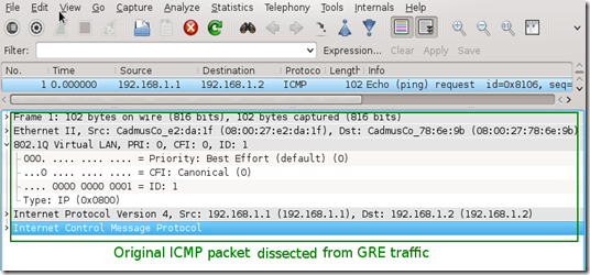
Again, generate some traffic in the subnet 192.168.1.0/24 and configure Wireshark to listen on interface mon0. Notice that the outer MAC and Ipv4 header are now stripped from the ICMP packet.

clip_image003

Picture 3 - Decapsulated Traffic Captured on Interface Eth1

Using RCDCAP for Decapsulating ERSPAN Traffic

RCDCAP is wrapper program that dissects the traffic and creates a virtual interface where the traffic is already decapsulated. I've compiled it from the source and created the Ubuntu package RCDCap-0.7.99-Linux for Ubuntu 15.04. Be aware that additional packages are needed to get it working.

janosik@onion:~$ sudo su
root@onion# apt-get install libboost-regex1.55.0

Use apt-get to install the packages below. If they are not available in a repository  download them from here and install manually with dpkg -i command.

  • libboost-program-options1.48.0_1.48.0-3_amd64.deb
  • libboost-thread1.48.0_1.48.0-3_amd64.deb
  • libboost-system1.48.0_1.48.0-3_amd64.deb

root@onion# dpkg -i libboost-program-options1.48.0_1.48.0-3_amd64.deb libboost-thread1.48.0_1.48.0-3_amd64.deb libboost-system1.48.0_1.48.0-3_amd64.deb

Now we can install RCDCAP with the command.

root@onion# dpkg -i RCDCap-0.7.99-Linux.deb

Once RCDCAP is installed configure interface eth1 to prepare for capturing.

janosik@onion:~$ sudo su
root@onion# ip addr add dev eth1 10.230.10.1/24
root@onion# ip link set dev eth1 mtu 1900
root@onion# ip link set dev eth1 up

Start RCDCAP with the command below and let Wireshark to listen on interface mon1.

root@onion# rcdcap -i eth1 --erspan --tap-persist --tap-device mon1 --expression "host 10.230.10.1"

We can see that RCDCAP have dissected monitored traffic from GRE and only original MAC + IPv4 + ICMP headers and pyaload are presented in Wireshark output.

clip_image004

Picture 4 - Decapsulated Traffic Captured on Interface Mon1

Reference:

Taken From: http://brezular.com/2015/05/03/decapsulation-erspan-traffic-with-open-source-tools/

Thursday, April 30, 2015

Windows 8.x as an Wifi Access Point

CONFIGURE WINDOWS 8 & 8.1 TO PROVIDE SECURE WIRELESS ACCESS POINT SERVICES TO WI-FI CLIENTS - TURN WINDOWS 8 INTO AN ACCESS POINT

POSTED IN WINDOWS 8 & WINDOWS 8.1

Windows 8 and Windows 8.1 (including Professional edition) operating systems provide the ability to turn your workstation or laptop into a secure wireless access point, allowing wireless clients (including mobile devices) to connect to the local network or Internet. This feature can save you time, money and frustration when there is need to connect wireless devices to the network or Internet but there is no access point available.

In addition, using the method described below, you can turn your Windows system into a portable 3G router by connecting your workstation to your 3G provider (using your USB HSUPA/GPRS stick).

Windows 7 users can visit our article Configuring Windows 7 To Provide Secure Wireless Access Point Services to Wi-Fi Clients - Turn Windows into an Access Point

To begin, open your Network Connections window by pressing Windows Key + R combination to bring up the Run window, and typencpa.cpl and click OK:

clip_image002

Figure 1. Run Command – Network Connections

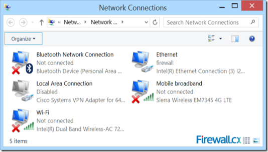
The Network Connection window will appear, displaying all network adapters the system current has installed:

clip_image003

Figure 2. Network Connections

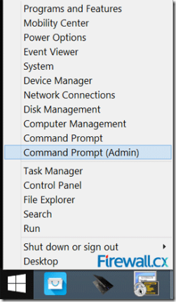
Let’s now create our new wireless virtual adapter that will be used as an access point for our wireless clients. To do this, open anelevated Command prompt (cmd) by right-clicking on the Window 8 start button located on the lower left corner of the desktop and select Command Prompt (Admin). If prompted by the User Account Control protection, simply click on Yes to proceed:

clip_image004

Figure 3. Opening an elevated Command Prompt

Once the command prompt is open, enter the following command to create the wireless network (SSID). The encryption used by default is WPA2-PSK/AES:

C:\windows\system32> netsh wlan set hostednetwork mode=allow ssid=Firewall.cx key=$connect$here

When the command is entered, the system will return the following information:

The hosted network mode has been set to allow.
The SSID of the hosted network has been successfully changed. 
The user key passphrase of the hosted network has been successfully changed.

In our example, the Wi-Fi (SSID) is named Firewall.cx and has a password of $connect$here.

The system information above confirms the creation of the wireless network and creates our virtual adapter which will be visible in theNetwork Connection window after the virtual adapter is enabled with the following command:

C:\windows\system32> netsh wlan start hostednetwork

Again, the system will confirm the wireless network has started with the below message:

The hosted network started.

Looking at the Network Connection window we’ll find our new adapter labeled as Local Area Connection 4. Right under the adapter is the SSID name of the wireless network created by the previous command:

clip_image005

Figure 4. Network Connections – Our new adapter appears

At this point, our new wireless network (Firewall.cx) should be visible to all nearby wireless clients.

Next, we need to enable Internet sharing on the network adapter that has Internet access. In our case this is the Ethernet adapter. Users accessing the Internet via their mobile broadband adapter should select their broadband adapter instead.

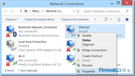
To enable Internet sharing, right-click on the Ethernet network adapter and select properties from the context menu, as shown below:

clip_image006

Figure 5. Network Connections – Ethernet Adapter Properties

Once the Ethernet adapter properties window appears, select the Sharing tab and tick the Allow other network users to connect through this computer’s Internet connection then select the newly created virtual adapter labelled Local Area Connection 4:

clip_image007

Figure 6. Enabling sharing and selecting the newly created virtual adapter

Be sure to untick the second option below (not clearly visible in above screenshot): Allow other network users to control or disable the shared Internet connection, then click on OK.

Notice our Ethernet adapter now has the word Shared in its description field:

clip_image008

Figure 7. Our Ethernet adapter now appears to be shared

At this point, clients that have successfully connected to our wireless SSID Firewall.cx should have Internet access.

Note that in some cases, it might be required to perform a quick restart of the operating system before wireless clients have Internet access. Remember that in case of a system restart, it is necessary to enter all command prompt commands again.

The command below will help verify the wireless clients connected to our Windows 8 access point:

C:\windows\system32> netsh wlan show hostednetwork

clip_image009

Figure 8. Information on our Windows 8 access point

As shown above, we have one wireless client connected to our Windows 8 access point. Windows 8 will support up to 100 wireless clients, even though that number is extremely likely to ever be reached.

This article showed how to turn your Windows 8 & Windows 8.1 operating system into a wireless access point, allowing wireless clients to connect to the Internet or Local LAN.

Taken From: http://www.firewall.cx/microsoft-knowledgebase/windows-8/1087-windows-8-secure-access-point.html


Friday, April 3, 2015

Arduino – EPLUG: Ethernet Controlled Power Plug

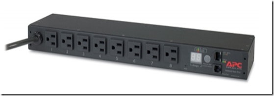
When I started  preparing for my CCNP SWITCH exam I bought some switches and set them up in my basement. After a couple of labs I realized I did a lot of trips to the basement to start / stop / restart the equipments. That’s when I started searching for remote controlled PDU, like this:
image

these are great but are very expensive for personal use (normally used in datacenters).

I already had an Arduino, so I started searching for a relay and cheap Ethernet NIC (the one on the arduino store was way to expensive), and I found the components below.

I put the components together and started programing the EPLUG program.

EPLUG is basically a small telnet Command Line Interface (CLI) that you can use to control multiple relays atached to Power Plugs. With this you can turn ON and OFF just about any electronic appliance you own from any device with telnet (PC, SmartPhone, Tablet, etc), using your Home Network or the Internet.
 
EPLUG was built as a framework that can be used for other projects. You can easily change the commands syntax by changing the text on the command patterns and add new commands by adding a new "else if(..){...}" statements on the "loop()" function.


Components

Relay Model: SRD-05VDC-SL-C

clip_image002

This relay board uses opto-couplers / opto-isolators to drive the relays, these isolate your Arduino from the relays, protecting it from voltage spikes. For more information check these videos:

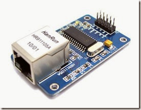
Ethernet NIC Model: HR911105A

Shield Version

image

Breakout Board Version

ENC28J60_1

when i bought these components i did some basic tutorials on wich we are going to build upon, so you should check them out for more details or to test each component individually:


EPLUG Prototype

The complete build looks like this:
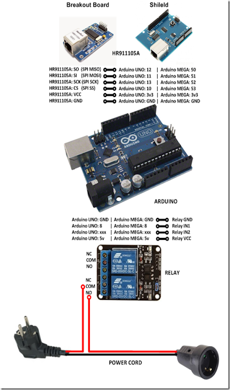
2015.04.04_Diagrama_Final

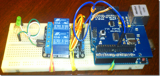
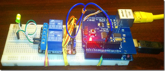
for the prototype I replaced the POWER CORD with an LED for testing:

image

my prototype looked like this:

image

The next step is to add the IP stack (uIP) for the Ethernet NIC (HR911105A).

You basically download the uIP IP stack here:

extract it, and put it on the arduino libraries folder

image


EPLUG as a Framework

The EPLUG program a simple and flexible Command Line Interface (CLI):

image

it receives the command on the function:

  • rcv_cmd(cmd, cmd_len)

 and matches them against the predefined patterns:
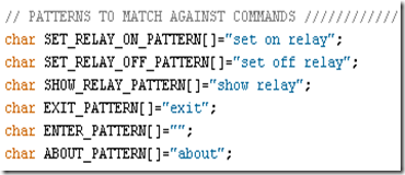
image

using the following functions:

  • cmd_equals (pattern,command) - exact match
  • cmd_startswith_l (pattern,command) - partial match, allow the commands to have a option (in this case the pin number)

and when it finds a match it executes an the function/actions for the corresponding command, as you can see below:
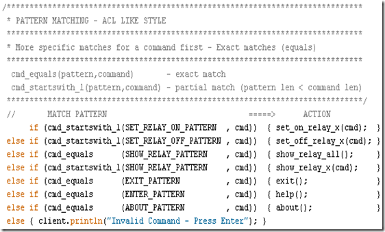
image

the structure above makes EPLUG very flexible, so that it’s easy to:

  • Change the current commands text
  • Add more commands (just add an else if (..){...} line)

my goal was to build EPLUG as a Framework for future projects.

For example if you want to do a program to set LEDs ON/OFF LEDs, you just need to change the patterns and the action functions and in 10 minutes or less your program is done.


Available Pins for Relays

There are some pins that that you should not use:
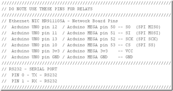
image

so you should only use the following pins:

  • Pin 2
  • Pin 3
  • Pin 4
  • Pin 5
  • Pin 6
  • Pin 7
  • Pin 8 I used this PIN
  • Pin 9

you can basically plug up to 8 relays to an Arduino UNO and controll them with the EPLUG program.


Loading EPLUG

Get the EPLUG code here:

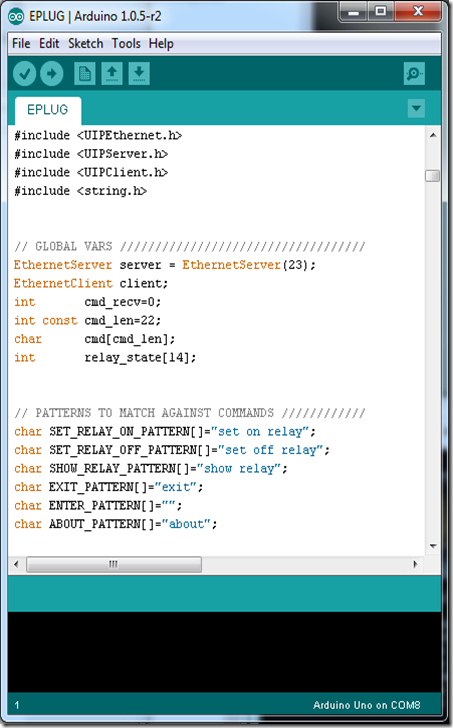
Open the EPLUG code on the Arduino IDE:
image

To upload the program to Arduino just press:

image

after compiling and uploading the IDE show the program size, and it should be 25.xxx bytes.

Problem: I found out that, for some reason, if the program is a bit over 26.000 bytes the Ethernet NIC doesn’t work properly. The maximum on the Arduino UNO is 32.256 bytes so this shouldn`t happen.


Testing EPLUG

First you need to find the IP of the Arduino NIC and make sure it’s on the correct network (your LAN network), you can do that here:

image

now telnet to it:

image

press ENTER to start the CLI and show the options:
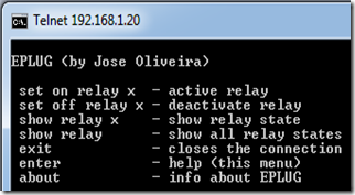
image

to set the “relay” (for now the LED) on you type:

image

you should get something like this:

Prototype1

Problem: After some time (1-3 min) the LED goes off for no aparent reason. After some research I found that this behavior is the the Arduino’s In System Programer (ISP) checking  if you want to reprogram Arduino from your PC (basically resets Arduino). The solution is very simple, you just don’t power the Arduino from your PC, you use a power supply.

to show the “relay” (LED) current state, you type:

image

to show all the “relays” (LEDs) current state, you type:

image

to set off the “relay” (LED), you type:

image

to show info about EPLUG, you type:

image

to close the telnet session, you type:

image


Putting It All Together

Now we can replace the LED with the POWER CORD, and use/test EPLUG in the real world.
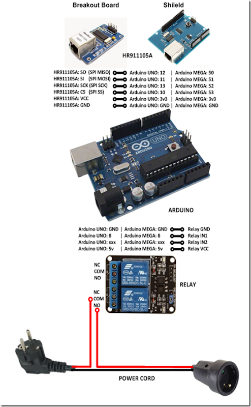
2015.04.04_Diagrama_Final

In this diagram the POWER CORD starts OFF, if you want it to start ON just change the wire on the relay from NO (normally open) to NC (normally closed).

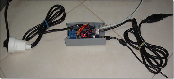
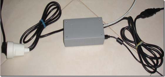
My build looked like this:
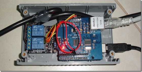
REAL1

image

image

now you can test/use it in the real world, check out my test video:
EPLUG Test

Next Steps

  • Add an internal USB power supply
  • Make it a lot smaller/cheaper (microntroller + breakout board)
  • Make a version with GSM aka GPLUG (SMS or GPRS)
  • Make a version with Radio modules aka RPLUG
  • Map relays to numbers different from the PINs
  • Save the pins state to a non-volatile memory (EEPROM)
  • Add a current sensor

Check out my makers community at: