Monday, March 19, 2012

DNS with a DD-WRT Router

Setup Local/Internal DNS with a DD-WRT Router

I’ve talked about some features of the DD-WRT router before, and one of the things I’ve been playing around with lately is DNSMasq. There’s a good chance you haven’t noticed this setting in DD-WRT because it’s not something most people would ever think to use. Plus DNSMasq can be found in two different areas within DD-WRT since it can be used for both DHCP assignments as well as internal/local DNS management. What I will be focusing on is the local DNS aspect.

When is using DNSMasq useful for controlling DNS? Here are some examples as to why you may want to use it:


  • You have DNS pointing to something that is hosted on your home network and it is also accessible from outside your network. For example, you may have a security camera that has a domain attached to it (e.g. camera.example.com), and it’s accessed from both on and off your network. Using DNSMasq on your router you can make the domain, camera.example.com, point to the internal IP of the camera so that anyone who accesses that camera from within your network won’t have to rely on external DNS getting resolved. You should see at least a slight performance boost that way.


  • You want to override public DNS entries, such as google.com. You can obviously pull off some great pranks by directing traffic to sites like google.com or facebook.com to some custom site you create, but there are other reasons this is legitimately useful. Maybe you are testing a new version of your own website, but want to make sure it will work fine with the live domain. DNSMasq can help you accomplish that.


  • You want to create DNS for a site that is accessible using only a single word, such as intranet. Companies do this kind of thing all the time where an internal-only website can be reached without needing or wanting a publicly-accessible URL.


I know what you may be thinking… why wouldn’t you just update the HOSTS file on your local machine? Well, you could, but not all devices support that feature. By using DNSMasq the DNS change will work for anything connecting to your router, including mobile devices such as phones and tablets.

So what do you have to change in DD-WRT? Here’s what you need to do:

  1. Go to the Services tab once you’ve logged into the administration interface.
  2. Find the section labeled DNSMasq, and make sure the DNSMasq option is enabled.
  3. This is the fun part. In the Additional DNSMasq Options box type out your local DNS configurations in the format of one entry per line:
    • address=/machine_or_domain_name/ip_address – where machine_or_domain_name is what you want to create/change DNS for (e.g. camera.example.com, google.com, intranet) and ip_address is the new IP address you want it to point to.
  4. Apply the settings to DD-WRT, and you should be all set.

This is an example of what your DNSMasq settings may look like:

Ddwrt dnsmasq

If your devices don’t see the changes after they’ve been made you may need to try restarting them since that is often the simplest way to clear the DNS cache.

Taken From: http://cybernetnews.com/local-internal-dns-ddwrt/

Sunday, March 18, 2012

PuTTY With Multiple Windows (Tabs)

Get Tabs for your PuTTY

It seems like everybody uses the free PuTTY client for accessing SSH from Windows, but the lack of a tabbed interface has kept me using the commercial SecureCRT application for years… until now.

With the PuTTY Connection Manager you can not only use tabs, but also wrap PuTTY in a slick interface. The underlying client is still the same putty.exe that you are used to… in fact the application doesn’t even come bundled with it.

The first time you launch the application you’ll be asked to enter the location to your copy of PuTTY.

clip_image002

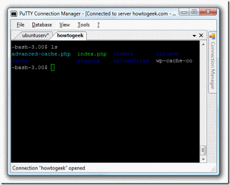
And finally, a tabbed version of PuTTY!

clip_image004

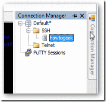
The connection manager can be docked to the side by using the little pushpin button.

clip_image006

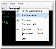
Right-clicking on a tab or using the Tools menu will allow you to get to the PuTTY menu

clip_image008

In the configuration dialog you can specify a bunch of options including an automatic login macro or passing command line parameters to putty.

clip_image010

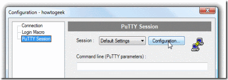
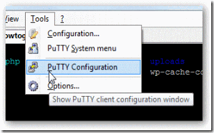
You can either click the configuration button above, or choose PuTTY Configuration from the tools menu.

clip_image012

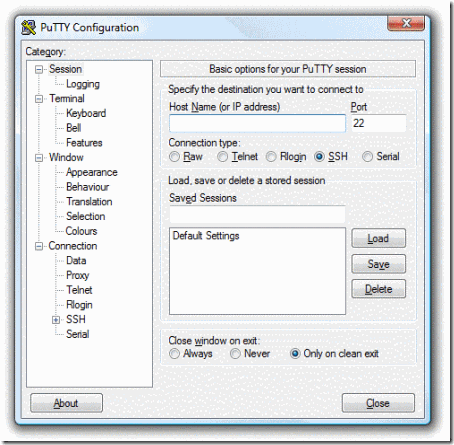
Which brings up the PuTTY Configuration dialog for the actual putty.exe underlying application.

clip_image014

There’s a lot more features to this application that I haven’t gotten to yet… you can even change the theme.

Download PuTTY Connection Manager from puttycm.free.fr

Taken From: http://www.howtogeek.com/howto/the-geek-blog/get-tabs-for-your-putty/

Thursday, March 15, 2012

Enterasys Switches Crash Course

[ Login & Password ]

If admin / siemens doesn't work, try admin/none
default, no pwd, just enter
user : admin, rw, ro


C2(SU)-> set system login 'username' {super-user|read-write|read-only}{enale|disable}
C2(SU)-> clear system login 'username'
C2(SU)-> show system login
for rw and ro = set password
for admin = set system login
C2(SU)-> set password rw
C2(SU)-> set system password length 7


[ Assign IP address ]

C2(SU)-> set ip address x.x.x.x mask x.x.x.x gateway x.x.x.x
C2(SU)-> clear ip address
[ Webview ]

Default : enable
C2(SU)-> show webview : to see status of webview (default enable)
C2(SU)-> set webview enable : to enable webview
- login : http://172.16.2.10
C2(SU)-> show webview
WebView is Enabled


[ Set time ]
C2(SU)-> set time 7:50:00
C2(SU)-> set summertime enable

[ Set prompt ]
C2(SU)-> set prompt "switch 1"

[ Set system contact ]
C2(SU)-> set system name "Enterasys-C2.1"
C2(SU)-> set system location "Main Bldg 2nd Floor"
C2(SU)-> set system contact "ipBalance Admin (            888-999-0000      )Mr.admin@ipBalance.com This e-mail address is being protected from spambots. You need JavaScript enabled to view it "

[ Save configuration ]
C2(SU)-> save config

[ Configure ]
C2(SU)-> configure configs/Jan1_2004.cfg

[ Set command ]
C2(SU)-> set switch description 1 : describe switch name or location
C2(SU)-> set ip address {x.x.x.x} mask {255.255.255.0} gateway {x.x.x.x}
C2(SU)-> clear ip address
C2(SU)-> set time [mm/dd/yyyy][hh:mm:ss]
C2(SU)-> set logout 10 : closing session idle in 10 min
C2(SU)-> set port [enable|diable]
C2(SU)-> set port duplex
C2(SU)-> set cdp state disable fe.1.2
C2(SU)-> set cdp state disable fe.1.3
C2(SU)-> set vlan create 2
C2(SU)-> set vlan create 3
C2(SU)-> set vlan name 1 Management
C2(SU)-> set vlan egress 1 fe.1.1 tagged
C2(SU)-> set vlan egress 1 fe.1.22 untagged
C2(SU)-> set vlan egress 2 fe.1.1 tagged
C2(SU)-> set vlan egress 2 fe.1.2-14 untagged
C2(SU)-> set port alias fe.1.1 'To Computer room N1.1 Port 2'
C2(SU)-> set port vlan fe.1.14 2

[ show ]
C2(SU)-> show config port
C2(SU)-> show switch
C2(SU)-> show switch status 1
C2(SU)-> show system
C2(SU)-> show system hardware : to get serial#, MAC, Firmware version etc
C2(SU)-> show system utilization {cpu|storage}
C2(SU)-> show time
C2(SU)-> show console
C2(SU)-> show telnet
C2(SU)-> show system login : user login account info
C2(SU)-> show system lockout
C2(SU)-> show ip address
C2(SU)-> show ip protocol : shown "system IP address acquisition method: dhcp
C2(SU)-> show config port
C2(SU)-> show cdp
C2(SU)-> show port fe.1.14 (ex, show port *.*.*)
C2(SU)-> show port status fe.1.14 : shown on status of information for fe.1.14
C2(SU)-> show port counters fe.1.14
C2(SU)-> show port negotiation fe.1.14
C2(SU)-> show port broadcast fe.1.14
C2(SU)-> show spantree stats
C2(SU)-> show boot system

[ Lag ]
C2(SU)-> show lacp lag 0.1
C2(SU)-> set lacp enable
C2(SU)-> set lacp asyspri 1000
C2(SU)-> set lacp aadminkey lag.0.1 2000
C2(SU)-> set lacp static lag.0.6 fe.1.6
C2(SU)-> set lacp singleportlag enable
C2(SU)-> set port lacp fe.3.16 aadminkey 3555

[ Clear ]
C2(SU)-> clear config
C2(SU)-> clear vlan 3
C2(SU)-> clear vlan name 9
C2(SU)-> clear port vlan fe.1.3,fe.1.11
C2(SU)-> clear vlan egress 1 fe2.1
C2(SU)-> clear VNRAM

[ Reset ]
C2(SU)-> reset or reset 1 : reload switch 1

[ Configuration example ]
C2(SU)-> dir
C2(SU)-> show configuration outfile configs/
C2(SU)-> copy configs/ tftp://192.168.77.101/
using notepad, modify config
C2(SU)-> copy tftp://192.168.77.101/jan11_2006.cfg configs/jan11_2006.cfg
C2(SU)-> dir
C2(SU)-> configure configs/  : unit will reboot onto the modified config file
C2(SU)-> configure configs/Jan11_2006.cfg  :  to execute the"jan11_2006.cfg" configurationn file
C2(SU)-> delete configs/jan11_2006.cfg
C2(SU)-> clear config all
C2(SU)-> clear NVRAM
C2(SU)-> show snmp persistmode manual : manual save config
C2(SU)-> save config

[ Login & Password ]

If admin / siemens doesn't work, try admin/none
default, no pwd, just enter
user : admin, rw, ro

A2(SU)-> set system login 'username' {super-user|read-write|read-only}{enale|disable}
A2(SU)-> clear system login 'username'
A2(SU)-> show system login
for rw and ro = set password
for admin = set system login
A2(SU)-> set password rw
A2(SU)-> set system password length 7

[ Assign IP address ]
A2(SU)-> set ip address x.x.x.x mask x.x.x.x gateway x.x.x.x
A2(SU)-> clear ip address

[ Webview ]
Default : enable
A2(SU)-> show webview : to see status of webview (default enable)
A2(SU)-> set webview enable : to enable webview
- login : http://172.16.2.10
A2(SU)-> show webview
WebView is Enabled
[ Set time ]
A2(SU)-> set time 7:50:00
A2(SU)-> set summertime enable
[ Set prompt ]
A2(SU)-> set prompt "switch 1"
[ Set system contact ]
A2(SU)-> set system name "Enterasys-A2.1"
A2(SU)-> set system location "Main Bldg 2nd Floor"
A2(SU)-> set system contact "ipBalance Admin (            888-999-0000      ) Mr.admin@ipBalance.com "
 
[ Save configuration ]

A2(SU)-> save config

[ Configure ]
A2(SU)-> configure configs/Jan1_2004.cfg
[ Set command ]
A2(SU)-> set switch description 1 : describe switch name or location
A2(SU)-> set ip address {x.x.x.x} mask {255.255.255.0} gateway {x.x.x.x}
A2(SU)-> clear ip address
A2(SU)-> set time [mm/dd/yyyy][hh:mm:ss]
A2(SU)-> set logout 10 : closing session idle in 10 min
A2(SU)-> set port [enable|diable]
A2(SU)-> set port duplex
A2(SU)-> set cdp state disable fe.1.2
A2(SU)-> set cdp state disable fe.1.3
A2(SU)-> set vlan create 2
A2(SU)-> set vlan create 3
A2(SU)-> set vlan name 1 Management
A2(SU)-> set vlan egress 1 fe.1.1 tagged
A2(SU)-> set vlan egress 1 fe.1.22 untagged
A2(SU)-> set vlan egress 2 fe.1.1 tagged
A2(SU)-> set vlan egress 2 fe.1.2-14 untagged
A2(SU)-> set port alias fe.1.1 'To Computer room N1.1 Port 2'
A2(SU)-> set port vlan fe.1.14 2
[ show ]
A2(SU)-> show config port  :
A2(SU)-> show switch
A2(SU)-> show switch status 1
A2(SU)-> show system
A2(SU)-> show system hardware : to get serial#, MAC, Firmware version etc
A2(SU)-> show system utilization {cpu|storage}
A2(SU)-> show time
A2(SU)-> show console
A2(SU)-> show telnet
A2(SU)-> show system login : user login account info
A2(SU)-> show system lockout
A2(SU)-> show ip address
A2(SU)-> show ip protocol : shown "system IP address acquisition method: dhcp
A2(SU)-> show config port
A2(SU)-> show cdp
A2(SU)-> show port fe.1.14 (ex, show port *.*.*)
A2(SU)-> show port status fe.1.14 : shown on status of information for fe.1.14
A2(SU)-> show port counters fe.1.14
A2(SU)-> show port negotiation fe.1.14
A2(SU)-> show port broadcast fe.1.14
A2(SU)-> show spantree stats
A2(SU)-> show boot system
[ Lag ]
A2(SU)->
show lacp lag 0.1
A2(SU)-> set lacp enable
A2(SU)-> set lacp asyspri 1000
A2(SU)-> set lacp aadminkey lag.0.1 2000
A2(SU)-> set lacp static lag.0.6 fe.1.6
A2(SU)-> set lacp singleportlag enable
A2(SU)-> set port lacp fe.3.16 aadminkey 3555
[ Clear ]
A2(SU)-> clear config
A2(SU)-> clear vlan 3
A2(SU)-> clear vlan name 9
A2(SU)-> clear port vlan fe.1.3,fe.1.11
A2(SU)-> clear vlan egress 1 fe2.1
A2(SU)-> clear VNRAM
[ Reset ]
A2(SU)-> reset or reset 1 : reload switch 1

[ Configuration example ]
A2(SU)-> dir
A2(SU)-> show configuration outfile configs/
A2(SU)-> copy configs/ tftp://192.168.77.101/
using notepad, modify config
A2(SU)-> copy tftp://192.168.77.101/jan11_2006.cfg configs/jan11_2006.cfg
A2(SU)-> dir
A2(SU)-> configure configs/  : unit will reboot onto the modified config file
A2(SU)-> configure configs/Jan11_2006.cfg  :  to execute the"jan11_2006.cfg" configurationn file
A2(SU)-> delete configs/jan11_2006.cfg
A2(SU)-> clear config all
A2(SU)-> clear NVRAM
A2(SU)-> show snmp persistmode manual : manual save config
A2(SU)-> save config

[ Default Login & Password ]
Here is default  login passwords of the most Enterasys Switches.
A-Series, B-Series and C-Series Enterasys Switches.
User : admin
Password : [empty]
Try below commends to see current login

Enterasys_A2(SU)-> show system login
Password history size: 0 
Password aging        : disabled  
Username     Access           State  
admin          super-user      enabled 
ro               read-Only       enabled 
rw              read-write       enabled
To add user 'Chris' as a super-user
  Enterasys_A2(SU)-> set system login chris super-user enable
  Enterasys_A2(SU)-> show system login

Password history size: 0
Password aging        : disabled
Username     Access           State
admin       super-user          enabled
ro            read-Only           enabled
rw           read-write           enabled
chris         super-user           enabled
To delete user 'chris' from list

  Enterasys_A2(SU)-> clear system login chris

If you want to change password length 7
  Enterasys_A2(SU)-> set system password length 7

[ Syslog Server ]
While I was testing Splunk, I need to add more devices to Splunk index pages. This example shows how to configure Enterasys Switch to forward syslog message to the server. It's simple and easy to setup.
In this example, server's IP is 192.168.77.13 and UDP port 514 is used. Severity level is 8.

  Enterasys(su)>set logging server 1 ip-addr 192.168.77.12 port 514 severity 8 state enable

To verify

 
  Enterasys(su)>show logging server

IP Address    Facility   Severity      Description  Port  Status 
--------------------------------------------------------------- 1 192.168.77.12    local4    debugging(8)     default     514   enable
If you want to change default value to facility local 5 and severity 5, configure below.

Enterasys(su)>set logging default facility local 5 severity 5
To see currently logging severity levels for all applications on your devices, type below commands

Enterasys(su)>show logging application all

        Application   Current Severity Level
---------------------------------------------
89      CLIWEB                   6
90      SNMP                     6
91      STP                      6
92      Driver                   6
93      System                   6
94      Stacking                 6
112     UPN                      6
118     Router                   6
1(emergencies)  2(alerts)       3(critical)
4(errors)       5(warnings)     6(notifications)
7(information)  8(debugging)

[ Port Mirroring ]
source port 1/13
destinaion port 1/10

Console(Config)#interface Ethernet 1/1
Console(Config-if)#port monitor Ethernet 1/4
Console(Config-if)#

[ Upgrade Firmware ]
As you know Enterasys was named Cabletron company long long time ago. I guess more than decade Cabletron was one of strong vendor on switches market at that time. Due to I had really good experience with Cabletron product, I trust Enterasys's product line. Actually, I installed many Enterasys switches since 2005. Today, I just want to share a tip to upgrade firmware on Enterasys switches. Compare to generic 3rd party switch vendors, Enterasys release new firmware more often. Well, some of people might say due to all lot of bugs, but I like to say "Diligent and effort" (too much?).There are detailed documents from vendor, but this guide would be easier for beginner. Well, lets see what the steps to complete upgrading firmware are.
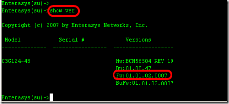
1. Find out what model of switch you are upgrading and what is current version of firmware running on the switch. Type "Show version" from the prompt.

- Model : C3G124-48
- Firmware : 01.01.02.0007

clip_image005
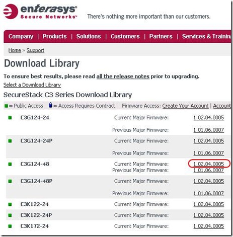
2. Go to the website "www.enterasys.com" and download proper firmware from the download library. and extract firmware to any folder your tftp server will use.

clip_image007

3. Assign IP address on the Enterasys switch in order to communicate with you computer which is running tftp server.
ex) computer 192.168.1.47, Enterasys switch is 192.168.1.8, default gateway .254

"set ip address 192.168.1.8 mask 255.255.255.0 gateway 192.168.1.254"


clip_image008
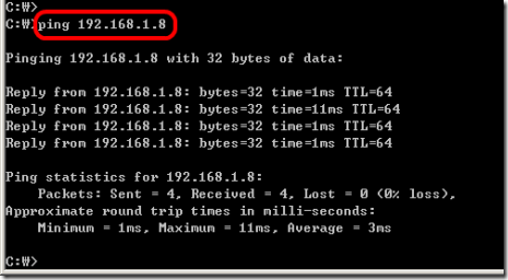
4. Ping the Enterasys switch from your computer.

clip_image009
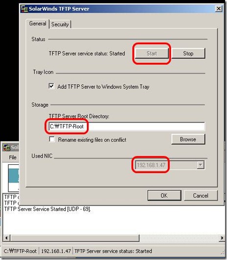
5. Execute tftp server. (If you don't have, just down one from solarwinds)

clip_image011
6. Copy firmware from tftp server

Enterasys(su)->copy tftp://192.168.1.47/c3-series_01.02.04.0005 system:image
- I will take time...to be done (few minutes)

7. From the switch, make sure new firmware is uploaded and check which firmware version is on active.

clip_image012
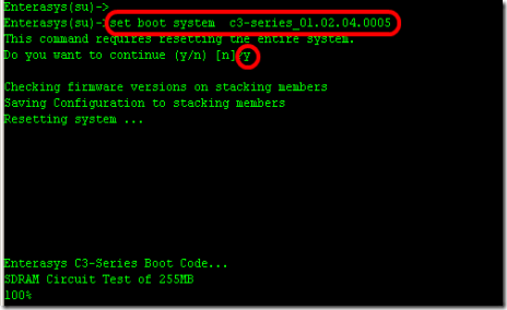
8. Type to "set boot system c3-series_01.02.04.0005" to booting up switch with new firmware(active).
B2(su)>>set boot system c3-series_01.02.04.0005
Do you want to replace ? (y/n) y
Automatically Enterasys switch will reboot.

clip_image013

9. Confirm now, new firmware is on active status.
The complete CLI reference manuals can be found at:

Enterasys C2 (Configuration Guide) :
http://www.penteknoloji.com.tr/destek/c2/1.pdf
Enterasys C3 (Configuration Guide): http://www.penteknoloji.com.tr/destek/c3/2.pdf

Monday, February 27, 2012

Cisco Etherchannel / Port-Channel (LACP / PAgP)

Etherchannel/Port-channel

On different Cisco switches it is possible to create logical connections that

are made-up off different fysical interface. It is needed that these interface

do have the same speed.

Most Cisco switches support max 64 etherchannels. These interfaces do not have to be contiguous.

or even on the same module. Each channel must be made up of min 2, max 8 interfaces.

The best is to use 2 ,4 or 8 interfaces. This will give the perfect load-balancing.

The load-balancing can be bases on layer 2/3 or 4 information.

It is not possible to have different load-balancing methods for different Etherchannels

on one switch. If the load-balancing method is change, it is applicable for all.

The load-balancing method can be:

- src-mac

- dst-mac

- src-dst-mac

- src-ip

- dst-ip

- src-dst-ip

- src-port

- dst-port

- src-dst-port

By using <port-channel load-balance {option}> it is possible to change to method.

If a single header is used to load-balance the low-order bits is used to dictate to

witch interface the frame is send. If two headers are used a XOR function is used on

the low-order bits.

It is possible to change what path with-in the etherchannel a frame takes by used the following command:

<test etherchannel load-balance interface port-channel [#] ip [src] [dst]>

to assign a physical interface towards a port-channel use the following command:

channel-group [#] mode on

There are two type of dynamic protocols to negotiate an etherchannels: PAgP and LACP 8021.AD

PAgP is Cisco proprietary

When these protocols start to communicate there is an exchange of information before the port-channel can be formed. The following items must match before a port-channel can form:

- same speed/duplex

- Access VLAN (if not trunked)

- Same trunking type, allowed VLAN and native VLAN (if trunked)

- Each port must have the same STP cost per VLAN with-in the portchannel

- No SPAN ports

channel-group [#] mode on (disables PAgP en LACP)

channel-group [#] mode off (disables PAgP en LACP and prevent the ports to form a port-channel)

channel-group [#] mode auto (use PAgP in a passive mode, it will wait until a PAgP packet will be send)

channel-group [#] mode passive (use LACP in a passive mode, it will wait until a PAgP packet will be send)

channel-group [#] mode desirable (use PAgP in an active mode, it will start to send PAgP packets)

channel-group [#] mode active (use LACP in an active mode, it will start to send LACP packets)

3750(config)#interface range gigabitethernet 1/0/2 – 4

3750(config-if-range)#channel-group 1 mode on

3750(config-if-range)#switchport

3750(config-if-range)#switchport trunk encapsulation dot1q

3750(config-if-range)#switchport mode trunk

First type the channel-group command. After that all interface commands will be automatically duplicated on all the interfaces group in the channel-group.

With LACP it is possible to create a port-channel on a stack (3560/3750 switches).

This is based on IOS version 12.2(25)SEE

Show command’s

· show interfaces port-channel [channel-group-number]

· show etherchannel [channel-group-number] summary

Verify command’s

  • test etherchannel load-balance interface port-channel [#] ip [src] [dst

Taken From: http://www.edgenetworks.nl/etherchannel.html

Monday, February 20, 2012

Soft RAID - Windows

If you�ve ever had the desire to RAID your hard drives for increased performance, but didn�t want to shell out the cash for additional hardware, then here is a practical solution for you. You can utilize a software RAID system through the use of dynamic disks if you happen to be the lucky owner of Windows 2000 or XP (Pro/Server).

Microsoft's Definition of Dynamic Disks (�dem fellers is smart)

Dynamic disks provide features that basic disks do not, such as the ability to create volumes that span multiple disks (spanned and striped volumes), and the ability to create fault-tolerant volumes (mirrored and RAID-5 volumes). All volumes on dynamic disks are known as dynamic volumes and can only be accessed by Windows 2000 or XP. You can perform the following tasks only on a dynamic disk:

  • Create and delete simple, spanned, striped, mirrored, and RAID-5 volumes.
  • Extend a simple or spanned volume.
  • Remove a mirror from a mirrored volume or split the volume into two volumes.
  • Repair mirrored or RAID-5 volumes.
  • Reactivate a missing or offline disk.
  • Check disk properties, such as capacity, available free space, and current status.
  • View volume and partition properties such as size, drive letter assignment, label, type, and file system.
  • Establish drive letter assignments for volumes or partitions, optical storage devices (for example CD-ROM), and removable drives.
  • Establish disk sharing and security arrangements for volumes and partitions formatted with NTFS.

RAID 101 - The Condensed Version

RAID = Redundant Array of Independent Disks. The key word here is redundant. RAID was developed for data backup reasons on file servers. The basic idea is to have two or more hard drives in a system and when data is written on one, the same data is duplicated on the other (mirroring), and quicker than you can say �deathstar� you have a reliable backup to your data. It was discovered that if you could care less about your data, and just wanted a screaming machine that you could configure two or more drives to act as one. So one set of data is split and written to multiple disks, and you know the old adage �two heads are better than one,� well in this case it is certainly true. Two drives retrieving or writing a file at the same time (striping) increases the efficiency significantly. Now of course there are several possible configurations for striping and mirroring drives in the same array, but since I�m one of those who could care less about my data, I will focus on striping and increasing performance.

Be aware that if you decide to undertake this delicate procedure that your data is at risk. If you have one drive go down then you�re your RAID configuration is no longer valid. Remember, striping splits your data among the drives, so if you lose a drive to failure you won�t be able to access the half files left behind on the good drive!

Just Like the Boy Scouts, Be Prepared!

Windows itself cannot reside on a striped partition. Does that mean you have to have a third drive just for Windows? No! Three drives? Money doesn�t grow on trees you know. Remember, we are being cheap..err�frugal here. However, if you happen to be independently wealthy, just as two heads are better than one, three must be thrice as good, and four must be force as good, huh?

You can pull this off without a format and reinstall of Windows if you already have Windows on its own partition. My recommendation is to back up your data and start from scratch.

Since I�ve convinced you to wipe your drives now, give some consideration to how you will be partitioning them. Keep in mind that to do software RAID it is not necessary to have matched drives. You could get this done with an 80GB and a 40GB without giving up drive space. This is an advantage over hardware RAID, which requires like drives to retain all drive space. However, even in the software setup, I would suspect performance would take a hit if one drive was significantly slower than the other, or the buffers were different sizes.

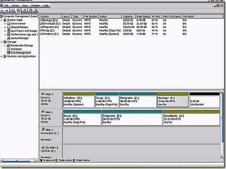
Here is how I partitioned using two 80GB Maxtor drives:

  • C: =10GB single drive for Windows
  • E: = 100GB on two drives (50GB on each drive striped).
  • F: =10GB Single drive for backups
  • G: = 25GB Single drive for downloads
  • Z: = 2GB on two drives (1GB on each drive striped) for the swapfile

Since Windows can�t be on a striped partition, and I would like to get the maximum benefit from striping, this is the volume on which I keep all program files and data such as My Documents, My Pictures, My Music, etc, etc, etc�. You may be asking yourself �how in the name of Pete do you move all that Windows stuff to a drive that doesn�t contain Windows?� Well, I could tell you, but then I�d have to kill you. Seriously, if you desire this information, feel free tocontact me.
For you visual types, here you go:

clip_image001

If you�re wondering what the 5.33 GB of unallocated space is for, that�s reserved for the day I figure out how to install Linux on a Windows dynamic disk� :p

One more thing, whether you use two, three, or four disks; the biggest performance gain is when each drive is on its own channel. In order to accomplish this with more than two drives, the addition of a PCI controller card is required. There we go spending money on hardware again, but the good news is an IDE controller is much less money than a quality RAID controller.

Throwing Caution to the Wind

Now we get down to the nuts and bolts. Turn off your computer and physically place each hard drive on its own channel. If for some reason you can�t get this done with your system don�t despair. You will still be able to do this, but the results just won�t be as good.

Next we need to do a clean install of Windows. What we are trying to accomplish with this step is to remove all partitions and create just one small one for Windows. The size is up to you, keep in mind that without a swapfile, My Documents, or program files; WinXP pro will take less than 2GB after the installation of SP1. You do need extra room to grow for things like system restore, the registry, and the many other things Windows manages to bloat it self with. Also, you will want free space to allow for later drive defragmentation. My recommendation is 5 to 10GB. After Windows is installed get all your updates done and your hardware installed.

Now that you have a nice fresh install of Windows and everything is working and up to date, right click on My Computer and click on �Manage�, this will bring up the Computer Management console. Just like everything else in Windows there are many ways to get to this, this is the one I prefer. Click on Disk Management and it will bring up a screen similar to the earlier image.

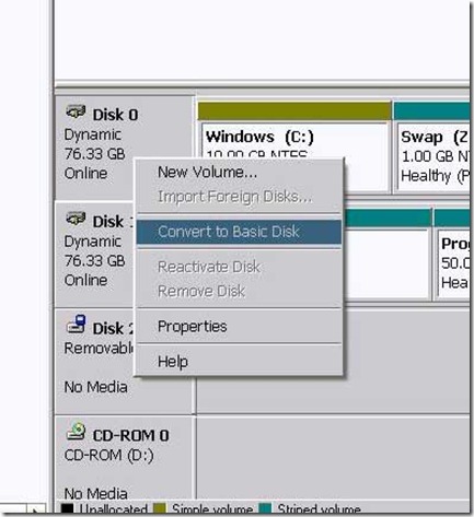
Convert all hard drives to dynamic by right clicking in the disk info box to the left of the partition graph and clicking on convert to Dynamic Disk. Select all drives that will be used for striping, follow the directions, read the warnings, and finish. Note in these images my drives are already converted and partitioned so options are grayed out or missing for me that won�t be for you.

clip_image002

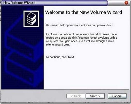
Now that you have dynamic disks, you can create your volumes (partitions) on them. Simply right click anywhere in the unallocated space of the drive where you want the partition be and select �new volume�. Now there will be a wizard to guide you through the process.

clip_image003

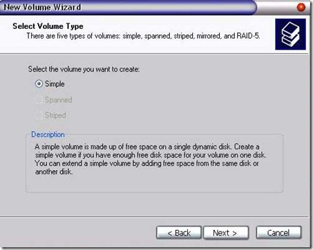
You will have a choice of simple, spanned, striped, and mirrored. The wizard provides descriptions of each selection. Be careful of the difference between striped and spanned, spanned will not give a performance increase. We will be using simple or striped. Depending on how you planned out your partitions make the appropriate choice and continue.

clip_image004

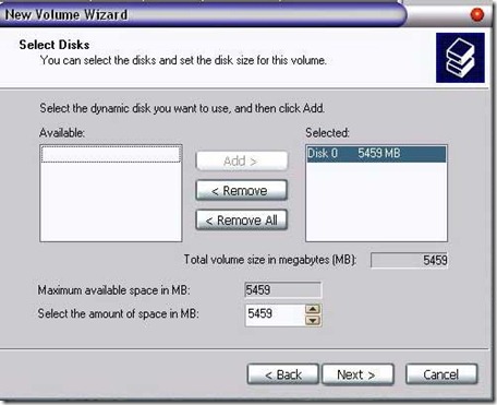
Next, for a simple volume, make sure the appropriate drive is selected and for striped volumes make sure all drives are selected. Dial in the size of the partition, for striped volumes this number will be the amount of space taken on one drive and the total size of the partition will be this number times the number of drives involved. For example if you were using two drives and you selected 10MB, the total partition size would be 20MB, 10 on each drive.

clip_image005

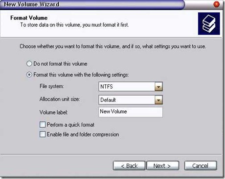
Continue and select a drive letter. Click next and select your file system, allocation unit size, and the name you want on this drive. I went with NTFS and default allocations.

clip_image006

Clicking next will give you an overview of what you selected, if it looks ok click finish. Continue in this manner until you have your drives partitioned the way you want them.

Now you are ready to move Your Documents and the pagefile off of the windows partition and on to the new ones you created. Install your software and you�re done. Bear in mind that most installs default to C:\Program Files, so remember to change the path when installing.

System as Tested

Processor:

AMD Athlon 2200+

Motherboard:

MSI KT7 Ultra 2 KT133A

Graphics Card:

ATI Radeon 9800 AGP

Memory:

768MB PC-133 SD-RAM

Hard Drive:

2x Maxtor 80GB 7200RPM 2MB Cache

Software:

Windows XP Pro SP1

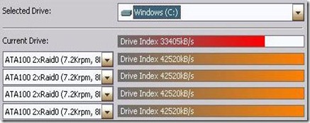
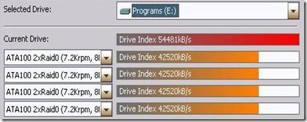
SiSoft Sandra is utilized for hard disk performance testing. As you can see my system is not state of the art, yet my results were significant during testing.

Default Drive Performance

clip_image007

Software RAID Performance

clip_image008

Conclusion

This seems to be a good way to squeeze some extra performance from one of the slowest parts of your PC. I have noticed a significant improvement in load time, especially for games. The performance improves greatly with three and four drives, but I�m sure that is getting close to or exceeding the limits of the current PCI bus. Have fun and enjoy your new found performance boost.

Pros:

  • Inexpensive
  • Good performance increase
  • Easy to configure
  • No need for matched drives
  • Can do spanning and mirroring also

Cons:

  • Dynamic disks are only recognized by Windows 2000 or later
  • Small increase in CPU loading

Taken From: http://www.techimo.com/articles/index.pl?photo=149

GNS3 - PIX Firewall Emulation

PIX Firewall Emulation

GNS3 is also capable of emulating PIX firewalls. Once again, you’ll need to provide your own PIX image. If you want to run more than a restricted license, you’ll also need to have a valid serial number and activation keys.

Configuring Qemuwrapper and Cisco PIX image

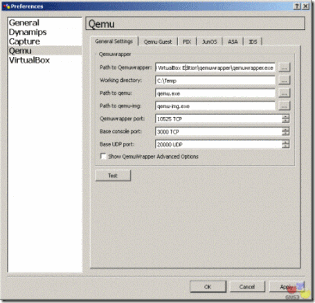
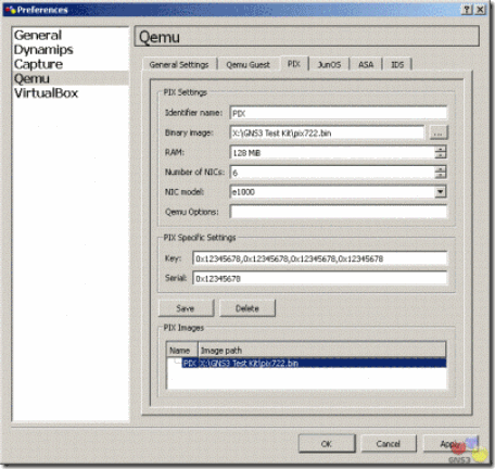
First, go to Preferences on the Edit menu in GNS3. Click on Qemu in the left pane. The default path to the Qemuwrapper should be fine. You may want to specify a different working directory. Note that Qemuwrapper is shipped with a compiled version of Pemu, therefore you do not need Qemu to emulate PIX.

On PIX tab, use the button next to Binary image to specify the location of your PIX operating system image. You may also change other settings like RAM or the number of interfaces. Once you are finished with the settings, click on Save.

clip_image002clip_image004

You may use the default Key and Serial number, if necessary. This will provide a restricted license with limited features. You will need a valid serial number and activation keys to access additional features. The graphic below on the left is a restricted image. Failover, VPN-DES, and VPN-3DES-AES are disabled. You are also limited to 6 physical interfaces and 25 VLANs. The graphic below on the right is unrestricted. With an unrestricted license, these features are enabled along with support for additional interfaces and VLANs.

clip_image006

If you have a serial number and valid activation keys, you may move from a restricted license to an unrestricted license. Type in the activation keys separated by commas with no spaces. Use all lower case. Be sure your serial number is converted to hexadecimal. It is usually in decimal in a show version command. Use a calculator to convert from decimal to hexadecimal if necessary.

Using Cisco PIX

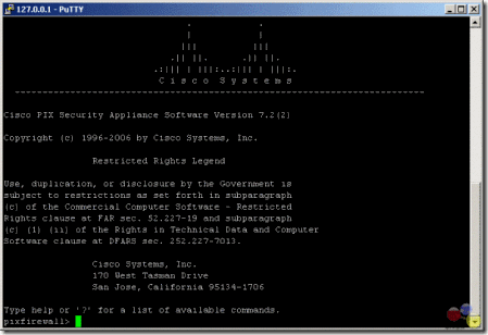
Click OK to return to the GNS3 main interface. Drag a PIX firewall icon from the Nodes Types pane into the workspace. Right-click FW1 and choose Start, then right-click on FW1 again and choose Console.

Once you console into your PIX firewall, issue a show version command. If the activation keys do not show up properly, then issue the following command from privileged mode (enable mode):

pixfirewall# activation-key 0x12345678 0x12345678 0x12345678 0x12345678

clip_image008

The command is issued on one line with spaces between the activation keys. Save the configuration using either the write command orcopy run start. Stop the device and restart it. Congratulations! Your PIX firewall is up and running.

Interfaces on the PIX are Ethernet interfaces. To connect to other devices, you’ll need to use either Ethernet or FastEthernet interfaces. You may not connect to a serial interface.

You may connect to other PIX firewalls, routers, and switches. You may not connect to a cloud. Consequently, to connect to a real network or to a Virtual PC, you’ll need to connect from the PIX to a switch, and then from the switch to your Cloud.

CPU usage with PIX

Just as with routers, CPU usage is an issue when emulating PIX firewalls on your computer. You will note that your CPU usage is most likely 100%. There are no idle-pc values available for PIX firewalls at this time. Instead, you may use third-party software to control your CPU usage. There are a variety of products on the market. The one that I use for Windows is called BES and is a free download.

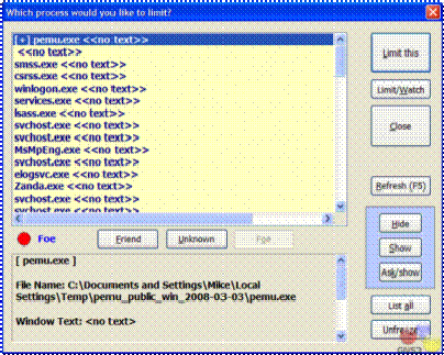
Complete documentation is available on the Web site along with the program download. Once you start your PIX firewall, start BES. Click the Target button. Choose the pemu.exe process and click the Limit this button. A confirmation screen will appear.

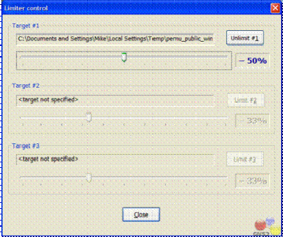
Click the Control button to control how much CPU limiting will be used. I’ve set mine to reduce CPU usage by 50%. If you are running multiple firewalls, you will want to limit each one. This program may also limit other processes running on your Windows computer.

clip_image010clip_image012

For Linux, use cpulimit. You may learn more about cpulimit at the following Web site: http://cpulimit.sf.net. On ubuntu you can use Synaptic Package Manager or Ubuntu Software Centre to download and install cpulimit.

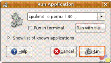
To run cpulimit, press F2 while holding the ALT key down (ALT+F2) in Ubuntu to open a Run Application box. Type the following in the box:

cpulimit –e pemu –l 40

clip_image014

This will limit the application pemu to 40% CPU usage.

Still in your Ubuntu, choose System Monitor under Administration on the System menu. Click the Resources tab. You should see that pemu process is running at 40% of your CPU usage.

Taken From: http://www.gns3.net/gns3-pix-firewall-emulation/

Tuesday, February 14, 2012

Cisco TSHOOT – Top 10 Show Commands

Cisco Router Tips
Top 10 'show' Commands by Tom Lancaster
clip_image002

One of the most important abilities a network administrator can have is the know-how to get information out of his network devices so he can find out what's going on with the network. In most networks, the staple of information gathering has been the "show" commands. Here are my top ten commands to know and love:

  1. show version: Start simple; this command gives uptime, info about your software and hardware and a few other details.
  2. show ip interface brief: This command is great for showing up/down status of your IP interfaces, as well as what the IP address is of each interface. It's mostly useful for displaying critical info about a lot of interfaces on one easy to read page.
  3. show interface: This is the more popular version of the command that shows detailed output of each interface. You'll usually want to specify a single interface or you'll have to hit 'page down' a lot. This command is useful because it shows traffic counters and also detailed info about duplex and other link-specific goodies.
  4. show ip interface: This often overlooked command is great for all the configuration options that are set. These include the switching mode, ACLs, header compression, ICMP redirection, accounting, NAT, policy routing, security level, etc. Basically, this command tells you how the interface is behaving.
  5. show ip route: This indispensable command shows your routing table, which is usually the primary purpose of the box. Get to know the options on this command.
  6. show arp: Can't ping a neighbor? Make sure you're getting an arp entry.
  7. show running-config: This is an easy one. It tells you how the box is configured right now. Also, "show startup-config" will tell you how the router will be configured after the next reboot.
  8. show port: Similar to the show interface command on routers, this command gives you the status of ports on a switch.
  9. show vlan: With the trend toward having lots of VLANs, check this command to make sure your ports are in the VLANs you think they are. Its output is very well designed.
  10. show tech-support: This command is great for collecting a lot of info. It basically runs a whole bunch of other show commands, and spits out dozens of pages of detailed output, designed to be sent to technical support. But, it's also useful for other purposes.

Taken From: http://www.thenetworkadministrator.com/ciscoroutertips.htm