Thursday, April 3, 2014

HP ProCurve Switch - Reset and Basic Configuration

clip_image001

Reset switch to factory defaults

If I’m not using brand new switch, I normally like to reset it back to factory defaults before doing anything.
Use a pointy object (like paper clip) and press “Reset” and “Clear” buttons on the front of the switch at the same time.
Release “Reset” button. When “Self Test” LED start to blink, release “Clear” button too. Now the switch should do it test routines. After that it should be back on factory defaults.

IP-Address

HP ProCurve Switch 2524# configure
HP ProCurve Switch 2524(config)# vlan 1
HP ProCurve Switch 2524(vlan-1)# ip address 10.0.0.1 255.255.255.0
HP ProCurve Switch 2524(vlan-1)# wr mem
HP ProCurve Switch 2524(vlan-1)# exit
HP ProCurve Switch 2524(config)# exit
HP ProCurve Switch 2524#

Configure VLANs

HP ProCurve Switch 2524# configure
HP ProCurve Switch 2524(config)# vlan 1
HP ProCurve Switch 2524(vlan-1)# name "Default"
HP ProCurve Switch 2524(vlan-1)# untag 2-6
HP ProCurve Switch 2524(vlan-1)# vlan 10
HP ProCurve Switch 2524(vlan-10)# name "First"
HP ProCurve Switch 2524(vlan-10)# untag 7-12
HP ProCurve Switch 2524(vlan-10)# vlan 20
HP ProCurve Switch 2524(vlan-20)# name "Second"
HP ProCurve Switch 2524(vlan-20)# untag 13-18
HP ProCurve Switch 2524(vlan-20)# exit
HP ProCurve Switch 2524(config)# exit
HP ProCurve Switch 2524#

Set up trunk ports

HP ProCurve Switch 2524# config
HP ProCurve Switch 2524(config)# trunk 23-24 trk1
HP ProCurve Switch 2524(config)# vlan 10
HP ProCurve Switch 2524(vlan-10)# tagged trk1
HP ProCurve Switch 2524(vlan-10)# vlan 20
HP ProCurve Switch 2524(vlan-20)# tagged trk1
HP ProCurve Switch 2524(vlan-20)# wr mem
HP ProCurve Switch 2524(vlan-20)# exit
HP ProCurve Switch 2524(config)# exit
HP ProCurve Switch 2524#

Disable all (but trunk) ports

HP ProCurve Switch 2524# configure
HP ProCurve Switch 2524(config)# int 2-22 disable
HP ProCurve Switch 2524(config)# wr mem
HP ProCurve Switch 2524(config)# exit
HP ProCurve Switch 2524#

Enable only necessary ports

HP ProCurve Switch 2524# configure
HP ProCurve Switch 2524(config)# int 2-4 enable
HP ProCurve Switch 2524(config)# int 13-15 enable
HP ProCurve Switch 2524(config)# wr mem
HP ProCurve Switch 2524(config)# exit
HP ProCurve Switch 2524#

Set up speed etc.

HP ProCurve Switch 2524# configure
HP ProCurve Switch 2524(config)# int 2-4 speed-duplex 100-full
HP ProCurve Switch 2524(config)# int 13-15 speed-duplex auto
HP ProCurve Switch 2524(config)# wr mem
HP ProCurve Switch 2524(config)# exit
HP ProCurve Switch 2524#

Set time and date

Time and date on hh:mm and mm:dd:yyyy format

HP ProCurve Switch 2524# configure
HP ProCurve Switch 2524(config)# time 10:05
Mon Jan 1 10:05:28 1990
HP ProCurve Switch 2524(config)# time 08/24/2010
Tue Aug 24 10:05:41 2010
HP ProCurve Switch 2524(config)# wr mem
HP ProCurve Switch 2524(config)# exit
HP ProCurve Switch 2524#

Set hostname

HP ProCurve Switch 2524# configure
HP ProCurve Switch 2524(config)# hostname "ServerRoom1"
ServerRoom1(config)# wr mem
ServerRoom1(config)# exit
ServerRoom1#

Backup settings

After running “sh run” copy/paste all between line which start with “hostname” to “ServerRoom1#” example to notepad and save that file.

ServerRoom1# sh run
ServerRoom1#

Restore settings from backup

All you have to do is copy/paste all (except the first “Running configuration:” line) to notepad on “Backup settings” part to “HP ProCurve Switch 2524#”.
If you have set operator and/or manager passwords, don’t copy/paste the lines which start with password.

HP ProCurve Switch 2524# configure
HP ProCurve Switch 2524(config)#

Set manager and operator password

ServerRoom1# configure
ServerRoom1(config)# password all
New password for Operator: ********
Please retype new password for Operator: ********
New password for Manager: ********
Please retype new password for Manager: ********
ServerRoom1(config)#

Update firmware using tftp server

If you are using windows machine and need tftp server software, you should try 3CDaemon. It’s free, portable, and it works like a dream =)

Download newest firmware from HP’s website: Software for switches.
For my switch HP ProCurve 2524gl, newest firmware was F.05.72. I downloaded 2300_2500-Software-F0572.zip package and extracted it to “2300_2500-Software-F0572″ folder.

Now I have directory “2300_2500-Software-F0572″ with 2300_2500-RelNotes-F0572-59903102.pdf (Release Notes). I also have F_05_72.swi file and this .swi file is the firmware which you are going to use to update your switch.

ServerRoom1# configure
ServerRoom1(config)# copy tftp flash 10.0.0.100 F_05_72.swi
Device will be rebooted, do you want to continue [y/n]? y
00126K

After F_05.72.swi is copied to the switch, you should get this kind of line. When eve everything goes ok your switch will reboot itself:

Validating and Writing System Software to FLASH...

Update firmware using xmodem over serial connection

I normally use Microsoft Hyperterminal when I’m doing this because it’s pretty easy to use xmodem to upload files with hyperterminal

Download newest firmware from HP’s website: Software for switches For my switch HP ProCurve 2524gl newest firmware was F.05.72 so I downloaded 2300_2500-Software-F0572.zip package and extracted it to “2300_2500-Software-F0572″.

Now I have directory “2300_2500-Software-F0572″ with 2300_2500-RelNotes-F0572-59903102.pdf (Release Notes) and F_05_72.swi file and this .swi file is the firmware which you are going to use to update your switch)

HP ProCurve Switch 2524# configure
HP ProCurve Switch 2524(config)# copy xmodem flash
The Primary OS Image will be deleted, continue [y/n]? y
Press 'Enter' and start XMODEM on your host...

After hitting ‘Enter’, start uploading using hyperterminal from menu: “Transfer” => “Send File…” then click “Browse…” and find that F_05_72.swi file and choose Xmodem (Not “1K Xmodem”) protocol. Then hit “Send” button. When everything is done you should see this kind of message and after that switch should boot:

Validating and Writing System Software to FLASH...

[note]This configuration was done with HP ProCurve 2524 (J4813A) but most of this command should work with other procurve switches too.[/note]

Related posts:

  1. HP ProCurve CLI CheatSheet
  2. How to reset Cisco Catalyst 2948G-L3 Switch
  3. Raspberry Pi: Get GPS Working with Kismet
  4. Raspberry Pi: Wireless Network

Taken From: http://blog.petrilopia.net/info/configuring-hp-procurve-switch/

PS4 Controller on your Mac or PC

Sony made a host of improvements to their controller, with the PlayStation 4′s DualShock 4. It seems slightly smaller, but the handholds are thicker, giving it a markedly more comfortable grip. The joysticks have been modified too, now convex and with a button click that’s easier to trigger. These and other changes make theDualShock 4 controller a joy to use. While we wait for PlayStation 4 games to grow in number, we’ll also show you how to use the DualShock 4 on your Mac or PC.

1. Connect the DualShock 4 to a PC

Using your DualShock 4 on a PC takes some tweaking to begin with, but compatibility is great. We’ll use DS4Tool, a wrapper application created by InhexSTER that makes the DualShock 4 look like an Xbox 360 controller. It’s thanks to this piggybacking off the support for the this device that we can ensure such good compatibility for the DualShock 4.

1.1 Download and Install Prerequisites

Before you’re able to use DS4Tool, you’ll need to install some prerequisite software on your computer. Start by downloading and installing the Xbox 360 Wireless Controller for Windows drivers. Also download the latest version of DS4Tool (currently 1.2.2) to your computer. The archive contains only executables, no installer wizard, so you’ll want to extract its contents to an easily accessible location on your computer.

Other prerequisites will be installed on a lot of PCs already. Verify, or re-install these if you are experiencing trouble:

o Microsoft .NET Framework 4.0

o Microsoft Visual C 2010 (or 2012) Runtime

o Latest DirectX Runtime

1.2 Install SCP Virtual Bus Driver

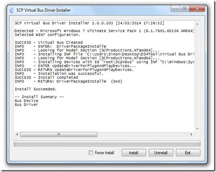
Head to the folder where you extracted DS4Tool in the previous step and run Virtual Bus Driver > SCPDriver.exe. Make sure to run it as Administrator, otherwise it won’t work.

clip_image001

In the application, press the Install button. This should only take a second. The application ends with an ‘Install Succeeded’ message, even if it failed. Check in the log that all operations are marked with SUCCESS, instead of ERROR. If you encounter errors, make sure you’re running the application as Administrator.

1.3 Connect the DualShock 4 Controller

This is where you connect your PlayStation 4′s DualShock 4 to your computer. You can use either a Micro-USB cable, like the one that comes with the PS4, or connect wirelessly over Bluetooth.

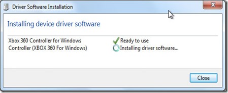
If you’re going with USB, just use a Micro-USB to connect your controller with your computer. Windows should recognise the device and start installing drivers. Easy as pie.

clip_image002

For Bluetooth, you’ll need a Bluetooth 2.1 and EDR (Enhanced Data Rate) support. First make sure your console and controller are both powered off. The LED light bar on the back of your controller should be off, too. Press and hold the PS and Share buttons on your controller until the LED light bar starts flashing. At this point, you should be able to pair with the controller on your computer’s Bluetooth Add Device menu. Chris Hoffman wrote a great walkthrough to pair with Bluetooth devices on Windows 7.

After playing over Bluetooth, press and hold the PS button to turn your controller off.

1.4 Run the DS4Tool Mapper

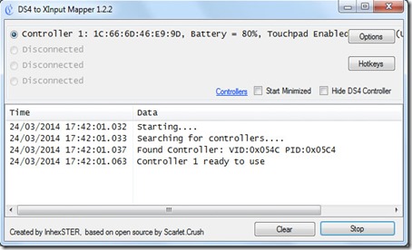
Go back to the folder to which you extracted DS4Tool and run ScpServer.exe. This is the application that actively maps the controls of your DualShock 4 controller to Xbox 360′s signals. If all went well, the application will recognize your controller as ‘Controller 1′.

clip_image003

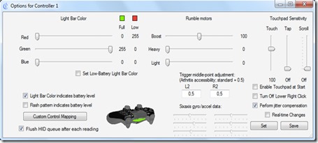
Press Options to tweak the settings for an individual controller. This is mostly for advanced users, so the golden rule of thumb is: if you don’t know what it’s for, don’t touch it. One fun extra is that you can let the Light Bar colour indicate battery level. To use this, tick off the box in the lower left and play with the colours above it.

clip_image004

There’s nothing more to it, so go play with your DualShock 4 controller! All games that support the Xbox 360 controller will now support yours out of the box.

2. Connect the DualShock 4 to a Mac

The set-up process for connecting a DualShock 4 to your Mac is a lot less complicated than for the PC. However, there’s also very little out of the box compatibility, so you’ll have to manually configure your controller for a lot of games.

2.1 Connect the DualShock 4 Controller

There are two ways to connect a DualShock 4 controller to your Mac. Either use a Micro-USB cable, like the one that comes with the PS4, or connect wirelessly over Bluetooth.

To connect over USB, just find a Micro-USB cable and plug your controller into your Mac. Your Mac will automatically detect it and the LED Light Bar on the controller back will light up.

clip_image005

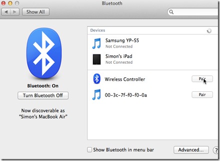
To connect over Bluetooth, first make sure your console and controller are both turned off. The Light Bar on the back should also be off. Go to System Preferences > Bluetooth and make sure Bluetooth is turned on. Hold the PS and Share buttons until the Light Bar starts flashing. When your controller shows up in the list of Bluetooth devices, press the pair button. The Light Bar will stop flashing after pairing.

After playing over Bluetooth, press and hold the PS button to turn your controller off.

2.2 Add Controller Mappings

At this point, your DualShock 4 is recognized by your Mac as a generic controller. Out of the box compatibility is scarce, however. Steam Big Picture works flawlessly and some games are catching on quick. If you want more extensive support, you’ll need to use a third-party controller mapper, basically binding buttons on your controller to key presses and mouse movements.

clip_image006

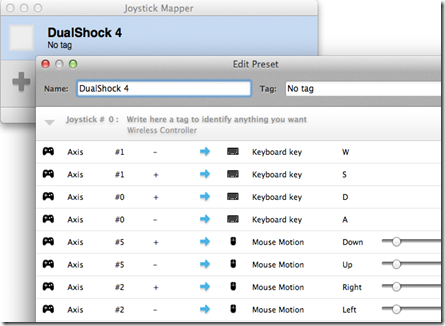
One of the best tools for the job is Joystick Mapper ($4.99). It’s perhaps the best controller mapper for Mac OS X, and definitely worth the five bucks if you regularly use a controller on your Mac. You’ll need to create a new preset and manually bind your controller buttons, D-pad and joysticks. You can create multiple presets to use different key bindings for different games.

clip_image007

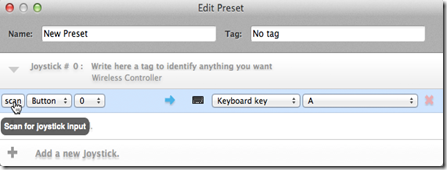
In your preset, first Add a new Joystick and then add your custom controls. For each button, or each joystick axis, press Add a new bind and press scan. Press and hold one of the controls on your DualShock 4 until Joystick Mapper picks it up and binds it to a key or mouse movement. When you’re finished, close the preset editing window and tick off the checkbox next to one of your presets to start using it. Just make sure to disable controller input in games that also pick up your generic controller, so the game controls aren’t triggered twice.

How are you going to use your DualShock 4 controller? Any specific games you have in mind? Share your experience in the comments section below the article!

Image credit: CraigJ

Taken From: http://www.makeuseof.com/tag/how-to-use-the-ps4-controller-on-your-mac-or-pc/

Sunday, March 23, 2014

Getting Arduino Online – Via the HR911105A Board + uIP TCP/IP Stack

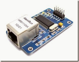
I have wanted to connect my arduino to my home network and also to the internet, for quite some time, so i bought this very cheap board, the HR911105A breakout board / NIC:

ENC28J60_1

I connected my Arduino Uno to it like this:

Arduino UNO pin 12 -- SO  (SPI MISO)
Arduino UNO pin 11 -- SI  (SPI MOSI)
Arduino UNO pin 13 -- SCK (SPI SCK)

Arduino UNO pin 10 -- CS  (SPI SS)
Arduino UNO 3v3    -- VCC
Arduino UNO GND   -- GND

I saw many webpages on the internet about connecting this board to the Arduino, and all said that the CS pin on the board connected to the Arduino pin 8, I tried it and i never worked (even with other TCP/IP stacks, besides the uIP). I searched the code and found out that i was actually the SPI SS pin, wich is pin 10 on the Arduino Uno.

image

to use it on the Arduino Mega, you need to connect it like this:

Arduino MEGA pin 50 -- SO  (SPI MISO)
Arduino MEGA pin 51 -- SI  (SPI MOSI)
Arduino MEGA pin 52 -- SCK (SPI SCK)
Arduino MEGA pin 53 -- CS  (SPI SS)
Arduino MEGA 3v3    -- VCC
Arduino MEGA GND   -- GND

I saw in the arduino page:

http://playground.arduino.cc/Hardware/ArduinoEthernet#.Uy4hFvl_tsM

that the uIP TCP/IP stack is available for the HR911105A Boards / NICs since October 2013 (just a coupple of months ago). You can find more information about this stack here:

http://en.wikipedia.org/wiki/UIP_(micro_IP)

this stack is quickly becoming the “de facto” standart for an for 8-and 16-bit microcontrollers, as you can see  even cisco is supporting it (“In October 2008, Cisco, Atmel, and SICS announced a fully compliant IPv6 extension to uIP, called uIPv6”)

I downloaded the uIP IP stack and followed the instructions here:

https://github.com/ntruchsess/arduino_uip

basically what I downloaded the uIP, extracted it, and put it on the arduino libraries folder

image

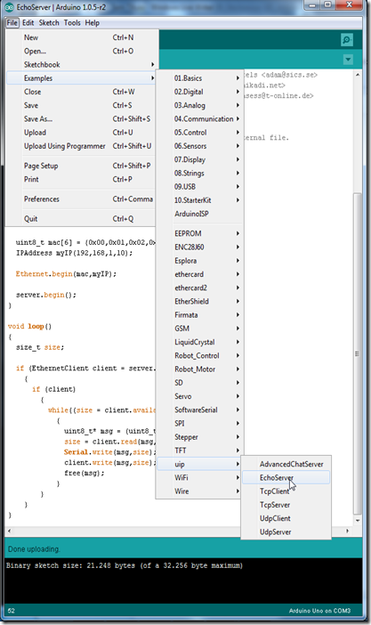
To test it, go to arduino IDE and select an example like the EchoServer

image

and change the IP, to one that it’s on your network (my network: 192.168.1.xx/24)

image

upload it to the Arduino and test it out.

FIrst ping it:

image

and then telnet into it, the EchoServer example will return all that you type:

image

image

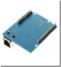
You can also buy the HR911105A module / NIC in the form of an Arduino Uno Shield:

imageimage

this version is a bit more expensive, but is the same as the breakout board. All the steps above are the same (you can go from the breakout board to the sheild without reprograming the Arduino), the main diference is that you don’t need to do the wiring:

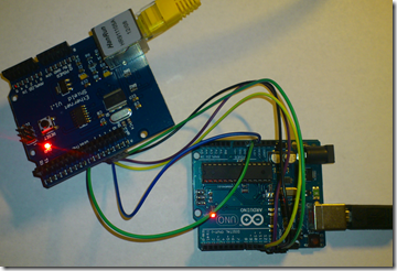
imageBut if you don’t want to put the shield on top of the arduino for some reason, you can connect it like this:

image

Arduino UNO pin 12 -- Shield  pin 12  (SPI MISO)
Arduino UNO pin 11 -- Shield  pin 11  (SPI MOSI)
Arduino UNO pin 13 -- Shield  pin 13  (SPI SCK)
Arduino UNO pin 10 -- Shield  pin 10  (SPI SS)
Arduino UNO 5v     -- Shield  pin 5v  (VCC)
Arduino UNO GND   -- Shield  pin GND (GND)

to use the Arduino Mega, just connect it like this:

Arduino MEGA pin 50 -- Shield  pin 12  (SPI MISO)
Arduino MEGA pin 51 -- Shield  pin 11  (SPI MOSI)
Arduino MEGA pin 52 -- Shield  pin 13  (SPI SCK)
Arduino MEGA pin 53 -- Shield  pin 10  (SPI SS)
Arduino MEGA 5v     -- Shield  pin 5v  (VCC)
Arduino MEGA GND    -- Shield  pin GND (GND)

And the internet of things / internet of everything starts Alegre


You can find the documentation about the uIP library here:

http://arduino.cc/en/Reference/Ethernet

this is not exactly the HR911105A breakout board / NIC documentation, but it the looks like it has the same methods / functions.


Check out my online community at: https://www.facebook.com/BragaLab

This post was made specially for the BragaLab fans

Saturday, March 1, 2014

ZenOss Core 4 – Installation

Zenoss Core 4 Installation
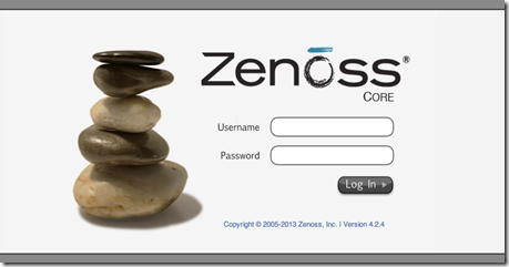
clip_image001

[1/24/2014: Post has been updated to reflect configuration with CentOS 6.5 and Zenoss Core 4.2.4
This is a sample installation guide for Zenoss Core 4. The single server installation closely aligns with the official Zenoss Core Installation Guide, but it also differs in some areas, and has a little more "glue".
The following components were used for this guide:

· CentOS

· Zenoss Core

· MariaDB

1. Hardware Requirements
You should meet these minimum hardware requirements for a single-server installation of Zenoss 4 Core (up to a 1000 devices):

Deployment Size

Memory

CPU

Storage

1 to 250 devices

4GB

2 cores

1 x 300GB (10K RPM or SSD)

250 to 500 devices

8GB

4 cores

1 x 300GB (10K RPM or SSD)

500 to 1000 devices

16GB

8 cores

1 x 300GB (15K RPM or SSD)

2. Operating System
My solution will be using the CentOS-6.5-x86_64-minimal.iso image. The aim of this image is to install a very basic CentOS 6.5 system, with the minimum number of packages needed to have a functional system. This post won't document the install process for CentOS 6 considering each environment (and associated requirements) is different. The main stages of the OS installation consist of language, storage, hostname, network, timezone, and the root password. 
Note: All commands are run within the context of the root account unless otherwise specified.
Make sure to update the system after the initial boot post install.

# yum -y update

I also install the following packages that are not included by default.

# yum -y install file ntp vim-enhanced man man-pages wget traceroute yum-utils

# hosts file
It's recommended to add a hostname entry (FQDN and short), of the local computer, to the hosts file. You can update the entry manually (via text editor), or run the following set of commands:

# ipv4addr=$(ip -f inet addr show dev eth0 | sed -n 's/^ *inet *\([.0-9]*\).*/\1/p')

# printf "$ipv4addr\t$(hostname -f)\t$(hostname -s)\n" >> /etc/hosts

# unset -v ipv4addr

Verify the entry.

# cat /etc/hosts

127.0.0.1 localhost localhost.localdomain localhost4 localhost4.localdomain4

::1 localhost localhost.localdomain localhost6 localhost6.localdomain6

10.1.206.43 zenoss.corp.example.com zenoss

# SELinux
Zenoss documentation states the requirement that SELinux be disabled. We can accomplish this by changing the SELINUX value to disabled in the /etc/sysconfig/selinux file. Modify the file with your text editor.

# vim /etc/sysconfig/selinux

# This file controls the state of SELinux on the system.

# SELINUX= can take one of these three values:

# enforcing - SELinux security policy is enforced.

# permissive - SELinux prints warnings instead of enforcing.

# disabled - No SELinux policy is loaded.

SELINUX=disabled

# SELINUXTYPE= can take one of these two values:

# targeted - Targeted processes are protected,

# mls - Multi Level Security protection.

SELINUXTYPE=targeted

Reboot the computer for the change to take effect.
After logging in after the reboot, verify SELinux is disabled. Run the following command:

# sestatus

SELinux status: disabled

# Network Time Protocol (NTP)
Time synchronization is an often overlooked, but a very essential, configuration step for new server deployments. In my configuration, I will have my zenoss server sync with an Active Directory domain controller (which holds the PDC emulator FSMO role) on my private network. We will need to modify the ntp.conf file with a text editor and start the NTP daemon process, and also set it for autostart at boot time. Notice I "comment out" the default public pool.ntp.org virtual cluster servers. You may want to leave these enabled if you don't have a particular time source to sync with.

# vim /etc/ntp.conf

...

# Permit all access over the loopback interface. This could

# be tightened as well, but to do so would effect some of

# the administrative functions.

restrict 127.0.0.1

restrict -6 ::1

# Hosts on local network are less restricted.

#restrict 192.168.1.0 mask 255.255.255.0 nomodify notrap

# Use public servers from the pool.ntp.org project.

# Please consider joining the pool (http://www.pool.ntp.org/join.html).

#server 0.centos.pool.ntp.org

#server 1.centos.pool.ntp.org

#server 2.centos.pool.ntp.org

# Use internal NTP Server (AD/DC01)

server 10.1.206.11 iburst

#broadcast 192.168.1.255 autokey # broadcast server

#broadcastclient # broadcast client

#broadcast 224.0.1.1 autokey # multicast server

#multicastclient 224.0.1.1 # multicast client

#manycastserver 239.255.254.254 # manycast server

#manycastclient 239.255.254.254 autokey # manycast client

...

Start the NTP daemon.

# service ntpd start

Starting ntpd: [ OK ]

Set the NTP daemon for autostart at boot time and verify.

# chkconfig ntpd on; chkconfig --list ntpd

ntpd 0:off 1:off 2:on 3:on 4:on 5:on 6:off

We can verify the NTP status by running the following command:

# ntpq -pn

remote refid st t when poll reach delay offset jitter

=================================================

*10.1.206.11 199.180.253.191 3 u 42 64 377 0.429 -69.204 58.561

# Firewall
Zenoss requires the following ports be open on the host firewall:

Port

Protocol

Direction

Description

11211

TCP/UDP

inbound

memcached

8080

TCP

inbound

Web interface

514

UDP

inbound

syslog

162

UDP

inbound

SNMP Traps

25

TCP

inbound

zenmail

Add the rules. It is recommended to add each rule with the iptables command, but I prefer to modify the /etc/sysconfig/iptables file directly with a text editor.

# vim /etc/sysconfig/iptables

# Firewall configuration written by system-config-firewall

# Manual customization of this file is not recommended.

*filter

:INPUT ACCEPT [0:0]

:FORWARD ACCEPT [0:0]

:OUTPUT ACCEPT [0:0]

-A INPUT -m state --state ESTABLISHED,RELATED -j ACCEPT

-A INPUT -p icmp -j ACCEPT

-A INPUT -i lo -j ACCEPT

-A INPUT -m state --state NEW -m tcp -p tcp --dport 22 -j ACCEPT

-A INPUT -m state --state NEW -m tcp -p tcp --dport 11211 -j ACCEPT

-A INPUT -m state --state NEW -m udp -p udp --dport 11211 -j ACCEPT

-A INPUT -m state --state NEW -m tcp -p tcp --dport 8080 -j ACCEPT

-A INPUT -m state --state NEW -m udp -p udp --dport 514 -j ACCEPT

-A INPUT -m state --state NEW -m udp -p udp --dport 162 -j ACCEPT

-A INPUT -m state --state NEW -m tcp -p tcp --dport 25 -j ACCEPT

-A INPUT -j REJECT --reject-with icmp-host-prohibited

-A FORWARD -j REJECT --reject-with icmp-host-prohibited

COMMIT

Restart the firewall service for the changes to take effect.

# service iptables restart

iptables: Flushing firewall rules: [ OK ]

iptables: Setting chains to policy ACCEPT: filter [ OK ]

iptables: Unloading modules: [ OK ]

iptables: Applying firewall rules: [ OK ]

# Oracle Java 6
From a client computer, browse to Oracle's Java Downloads and grab the latest Java Version 6 Linux x64 RPM file.
Transfer the file to the Zenoss server. The command/utility will vary depending on what client OS you're using. I recommend WinSCP or PSCP if using a Windows client. From a Linux or Mac OS X client, we can use the scp command. The following command will copy the file to root's home directory on the destination Zenoss server:

$ scp jre-6u45-linux-x64-rpm.bin root@10.1.206.43:

Back in our terminal for the Zenoss server, we now need to make the binary file executable.

# cd ~

# chmod u+x ./jre-6u45-linux-x64-rpm.bin

Install the Oracle Java Runtime Environment (JRE).

# ./jre-6u45-linux-x64-rpm.bin

Unpacking...

Checksumming...

Extracting...

UnZipSFX 5.50 of 17 February 2002, by Info-ZIP (Zip-Bugs@lists.wku.edu).

inflating: jre-6u45-linux-amd64.rpm

Preparing... ########################################### [100%]

1:jre ########################################### [100%]

Unpacking JAR files...

rt.jar...

jsse.jar...

charsets.jar...

localedata.jar...

plugin.jar...

javaws.jar...

deploy.jar...

Done.

Add the JAVA_HOME variable statement to the end of the system BASH profile file.

# echo 'export JAVA_HOME=/usr/java/default' >> /etc/profile

"Dot" source the system BASH profile file to add the JAVA_HOME variable to the current shell environment.

# . /etc/profile

Verify the variable is set and that Java is installed correctly.

# echo $JAVA_HOME

/usr/java/default

# java -version

java version "1.6.0_45"

Java(TM) SE Runtime Environment (build 1.6.0_45-b06)

Java HotSpot(TM) 64-Bit Server VM (build 20.45-b01, mixed mode)

3. Database
My solution diverges from the official Zenoss documentation. I prefer to deploy MariaDB instead of the standard MySQL server. MariaDB is an enhanced, drop-in replacement for MySQL. Visit theMariaDB website for more information.
Let's first add the MariaDB repo to our local YUM configuration.

# cat >> /etc/yum.repos.d/MariaDB.repo << EOF

> [mariadb]

> name = MariaDB

> baseurl = http://yum.mariadb.org/5.5/centos6-amd64

> gpgkey=https://yum.mariadb.org/RPM-GPG-KEY-MariaDB

> gpgcheck=1

> EOF

Verify.

# cat /etc/yum.repos.d/MariaDB.repo

[mariadb]

name = MariaDB

baseurl = http://yum.mariadb.org/5.5/centos6-amd64

gpgkey=https://yum.mariadb.org/RPM-GPG-KEY-MariaDB

gpgcheck=1

Then also verify the repository is enabled.

# yum repolist

Loaded plugins: fastestmirror

Loading mirror speeds from cached hostfile

* base: mirror.nwresd.org

* extras: mirrordenver.fdcservers.net

* updates: yum.phx.singlehop.com

mariadb | 1.9 kB 00:00

mariadb/primary_db | 15 kB 00:00

repo id repo name status

base CentOS-6 - Base 6,367

extras CentOS-6 - Extras 14

mariadb MariaDB 9

updates CentOS-6 - Updates 373

repolist: 6,763

Let's now install the required packages.

# yum -y install MariaDB-server MariaDB-client

After MariaDB has been installed, modify the MariaDB server.cnf configuration file with some recommended settings from Zenoss.

# vim /etc/my.cnf.d/server.cnf

...

# this is read by the standalone daemon and embedded servers

[server]

# this is only for the mysqld standalone daemon

[mysqld]

max_allowed_packet=16M

innodb_buffer_pool_size=256M

innodb_additional_mem_pool_size=20M

# this is only for embedded server

[embedded]

...

Start the MariaDB server.

# service mysql start

Starting MySQL.. SUCCESS!

Verify MariaDB is set for autostart at boot.

# chkconfig --list mysql

mysql 0:off 1:off 2:on 3:on 4:on 5:on 6:off

4. Zenoss Core
From a client computer, browse to the Zenoss Core site and grab the latest Zenoss Core 4 RPM package for RHEL/CentOS 6 64-bit (v4.2.4 at the date of this post).
Transfer the file to the Zenoss server. The command/utility will vary depending on what client OS you're using. I recommend WinSCP or PSCP if using a Windows client. From a Linux or Mac OS X client, we can use the scp command. The following command will copy the file to root's home directory on the destination Zenoss server:

$ scp zenoss_core-4.2.4-1897.el6.x86_64.rpm root@10.1.206.43:

Back in our terminal for the Zenoss server, install the Zenoss dependencies repositories.

# rpm -Uvh http://deps.zenoss.com/yum/zenossdeps-4.2.x-1.el6.noarch.rpm

Retrieving http://deps.zenoss.com/yum/zenossdeps-4.2.x-1.el6.noarch.rpm

Preparing... ########################################### [100%]

1:zenossdeps ########################################### [100%]

Verify the repositories are enabled.

# yum repolist

Loaded plugins: fastestmirror

Loading mirror speeds from cached hostfile

* base: mirror.nwresd.org

* extras: mirrordenver.fdcservers.net

* updates: yum.phx.singlehop.com

repo id repo name status

base CentOS-6 - Base 6,367

extras CentOS-6 - Extras 14

mariadb MariaDB 9

updates CentOS-6 - Updates 373

zenossdeps-repo Zenoss Dependencies - Base 18

zenossdeps-update-repo Zenoss Dependencies - Updates 0

repolist: 6,781

It's now time to install the Zenoss Core 4 package (and dependency packages).

# cd ~

# yum -y --nogpgcheck localinstall zenoss_core-4.2.4-1897.el6.x86_64.rpm

# memcached, rabbitmq-server, snmpd
Set the services to start automatically at boot, and also interactively start them.

# for svc in memcached rabbitmq-server snmpd; do chkconfig $svc on; service $svc start; done

# Start Zenoss
Run the following command to start Zenoss:

# service zenoss start

At this stage, Zenoss should be ready from a functional perspective. We now need to focus on securing the Zenoss server. 
5. Post-Install
The auto-deploy script offered by Zenoss runs a separate script that secures your Zenoss installation. Since we chose to do a normal install, we will have to manually fetch (and execute) the script. 
Switch to a login shell for the zenoss user.

# su -l zenoss

Verify the zenoss user shell. As a side note, that's an "interesting" UID number for the zenoss user. :-)

$ id

uid=1337(zenoss) gid=500(zenoss) groups=500(zenoss)

Download the secure_zenoss.sh file from GitHub.

$ wget --no-check-certificate https://raw.github.com/osu-sig/zenoss-autodeploy-4.2.3/master/secure_zenoss.sh

Before we run the script, let's get the default passwords for the zenoss user in the global.conf file.

$ egrep 'user|password' $ZENHOME/etc/global.conf | grep -v admin

zodb-user zenoss

zodb-password zenoss

amqpuser zenoss

amqppassword zenoss

zep-user zenoss

zep-password zenoss

Give the secure_zenoss.sh script the execute permission.

$ chmod u+x secure_zenoss.sh

Run the secure_zenoss.sh script. I opted not to change the MySQL (MariaDB) root password at this time. We will be performing that task in the next section.

$ ./secure_zenoss.sh

Restricting permissions on /opt/zenoss/etc/*.conf*

Assigning secure password for global.conf:zodb-password

Assigning secure password for global.conf:amqppassword

Assigning secure password for global.conf:zep-password

Assigning secure password for global.conf:hubpassword

Assigning secure password for hubpassword:admin

MySQL is configured with a blank root password.

Configure a secure MySQL root password? [Yn]: n

Forcing zeneventserver to only listen on 127.0.0.1:8084

Let's verify the passwords have been modified for the zenoss user in the global.conf file.

$ egrep 'user|password' $ZENHOME/etc/global.conf | grep -v admin

zodb-user zenoss

zodb-password 18zmcTgYsA+AjczljwQd

amqpuser zenoss

amqppassword 18zmcTgYsA+AjczljwQd

zep-user zenoss

zep-password 18zmcTgYsA+AjczljwQd

hubpassword 18zmcTgYsA+AjczljwQd

We will also need to modify the password in the zodb_db_main.conf and zodb_db_session.conf files to match the value set for the zodb-password property in the global.conf file. 
First, get the current configuration of these two files.

$ tail -n +1 $ZENHOME/etc/zodb_db_{main,session}.conf

==> /opt/zenoss/etc/zodb_db_main.conf <==

<mysql>

host localhost

port 3306

user zenoss

passwd zenoss

db zodb

</mysql>

==> /opt/zenoss/etc/zodb_db_session.conf <==

<mysql>

host localhost

port 3306

user zenoss

passwd zenoss

db zodb_session

</mysql>

Run the following commands to perform a substitution of the passwd property value for each of the files:

$ zodbpw=$(grep zodb-password $ZENHOME/etc/global.conf | awk '{print $2}')

$ sed -i.orig "5s/zenoss/$zodbpw/" $ZENHOME/etc/zodb_db_{main,session}.conf

$ unset -v zodbpw

Verify the modification was successful.

$ tail -n +1 $ZENHOME/etc/zodb_db_{main,session}.conf

==> /opt/zenoss/etc/zodb_db_main.conf <==

<mysql>

host localhost

port 3306

user zenoss

passwd 18zmcTgYsA+AjczljwQd

db zodb

</mysql>

==> /opt/zenoss/etc/zodb_db_session.conf <==

<mysql>

host localhost

port 3306

user zenoss

passwd 18zmcTgYsA+AjczljwQd

db zodb_session

</mysql>

Exit out of the shell for the zenoss user to return to the root user shell.

$ exit

logout

# MariaDB
The interactive mysql_secure_installation command improves the security of your MariaDB installation. It will allow you to set your MariaDB (MySQL) root password as well as other security related operations.

# mysql_secure_installation

The password for the MariaDB database zenoss user will also need to be set to "sync up" with the previous password modifications. We will use the value set for the passwd property in thezodb_db_* config files.

# mysql -u root -p

Enter password: <mysql_root_password>

Welcome to the MariaDB monitor. Commands end with ; or \g.

Your MariaDB connection id is 234

Server version: 5.5.34-MariaDB MariaDB Server

Copyright (c) 2000, 2013, Oracle, Monty Program Ab and others.

Type 'help;' or '\h' for help. Type '\c' to clear the current input statement.

MariaDB [(none)]> SET PASSWORD FOR 'zenoss'@'localhost' = PASSWORD('18zmcTgYsA+AjczljwQd');

Query OK, 0 rows affected (0.00 sec)

MariaDB [(none)]> \q

Bye

Restart the MariaDB server.

# service mysql restart

Shutting down MySQL. SUCCESS!

Starting MySQL.. SUCCESS!

# RabbitMQ
The following script will ensure the proper Zenoss credentials/permissions are set for the AMQP entities. 
Create the set-rabbitmq-perms.sh script file.

# vim set-rabbitmq-perms.sh

Enter the following information (exclude the line numbers), then save the file:

001 002 003 004 005 006 007 008 009 010 011 012 013 014 015 016 017 018 019 020 021 022 023 024 025

#!/usr/bin/env bash set -e VHOSTS="/zenoss" USER="zenoss" PASS="grep amqppassword \$ZENHOME/etc/global.conf | awk '{print \$2}'" if [ $(id -u) -eq 0 ] then RABBITMQCTL=$(which rabbitmqctl) $RABBITMQCTL stop_app $RABBITMQCTL reset $RABBITMQCTL start_app $RABBITMQCTL add_user "$USER" "$(su -l zenoss -c "$PASS")" for vhost in $VHOSTS; do $RABBITMQCTL add_vhost "$vhost" $RABBITMQCTL set_permissions -p "$vhost" "$USER" '.*' '.*' '.*' done exit 0 else echo "Error: Run this script as the root user." >&2 exit 1 fi

Give the script file the execute permission.

# chmod u+x set-rabbitmq-perms.sh

Run the script.

# ./set-rabbitmq-perms.sh

Stopping node rabbit@zenoss ...

...done.

Resetting node rabbit@zenoss ...

...done.

Starting node rabbit@zenoss ...

...done.

Creating user "zenoss" ...

...done.

Creating vhost "/zenoss" ...

...done.

Setting permissions for user "zenoss" in vhost "/zenoss" ...

...done.

Restart the rabbitmq-server daemon.

# service rabbitmq-server restart

Restarting rabbitmq-server: SUCCESS

rabbitmq-server.

Restart Zenoss.

# service zenoss restart

# Verification
Verify all Zenoss daemons are running.

# su -l zenoss -c 'zenoss status'

Daemon: zeneventserver program running; pid=10564

Daemon: zopectl program running; pid=10662

Daemon: zenrrdcached program running; pid=10667

Daemon: zenhub program running; pid=10730

Daemon: zenjobs program running; pid=10777

Daemon: zeneventd program running; pid=10831

Daemon: zenping program running; pid=10907

Daemon: zensyslog program running; pid=11035

Daemon: zenstatus program running; pid=11026

Daemon: zenactiond program running; pid=11064

Daemon: zentrap program running; pid=11185

Daemon: zenmodeler program running; pid=11196

Daemon: zenperfsnmp program running; pid=11222

Daemon: zencommand program running; pid=11254

Daemon: zenprocess program running; pid=11282

Daemon: zredis program running; pid=11283

Daemon: zenjmx program running; pid=11410

Daemon: zenwin program running; pid=11600

Daemon: zenwinperf program running; pid=11758

Daemon: zeneventlog program running; pid=11910

If the proper permissions have been set for the RabbitMQ zenoss vhost(s), then the following queues should be listed:

# rabbitmqctl -p /zenoss list_queues

Listing queues ...

celery 0

zenoss.queues.zep.migrated.summary 0

zenoss.queues.zep.migrated.archive 0

zenoss.corp.example.com.celeryd.pidbox 0

zenoss.queues.zep.rawevents 0

zenoss.queues.zep.heartbeats 0

zenoss.queues.zep.zenevents 0

zenoss.queues.zep.signal 0

zenoss.queues.zep.modelchange 0

...done.

6. Web Interface Setup Wizard
After the preceding steps have been completed, you are ready to start the Setup Wizard for the initial configuration of customizing Zenoss for your environment. On your client computer, open a web browser and type http://zenoss.corp.example.com:8080 (or http://10.1.206.43:8080) in the address field.

Taken From: http://binarynature.blogspot.pt/2012/11/zenoss-core-4-installation.html

Thursday, February 27, 2014

Create an Cisco ASA VM - VMware

Create a Cisco ASA VM in VMware Fusion

clip_image001

DISCLAIMER: The information provided herein is for general informational and educational purposes only. 
This post provides a solution on how to create a Cisco ASA device in VMware Fusion for the Mac. Why do this? Well, the most documented method to integrate the Cisco ASA with GNS3 is by having it run on the QEMU hypervisor. Since VMware Fusion 6 can integrate with GNS3 (check out my previous post), we now have another hypervisor option to bring the Cisco ASA into the GNS3 environment. 
The following components were used for this tutorial:

· Mac OS X 10.9 (Mavericks)

· VMware Fusion 6.0

· Fedora 20 LXDE Spin (32-bit PC Edition)

· Cisco ASA 8.4(2) image file

1. Create the ASAVM directory
This will be the working directory for our project. You can create the folder (directory) in the GUI, but I will use the command line method in my example. Run the following command from Terminal:

$ mkdir $HOME/Documents/ASAVM

2. Copy/Move the Cisco ASA image file to the ASAVM directory
Again, feel free to copy/move the file in the GUI, but I will use the command line method. In my example, I will copy the file from myDownloads/Labs directory to the Documents/ASAVM directory. Run the following command from Terminal:

$ cp $HOME/Downloads/Labs/asa842-k8.bin $HOME/Documents/ASAVM

3. Create the repack.v4.1.sh script file
Web forum member dmz is the author of the script that allows us to run the Cisco ASA 8.4(2) software on virtualization hypervisors. The script essentially unpacks the original ASA software binary file, performs patch operations, and repacks the files (and optionally creates a bootable ISO image file). Many thanks to dmz for providing the script as I'm sure this was a very difficult process to reverse engineer and debug. Visit the web forum post at 7200emu.hacki.at for more information. 
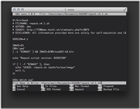
Create the repack.v4.1.sh script file with the nano text editor. Run the following command from Terminal:

$ nano $HOME/Documents/ASAVM/repack.v4.1.sh

Copy the code from GitHub and paste (command + v) the contents into the text editor window.

clip_image002

Save (control + o) the file, press the enter key to confirm, then exit (control + x) the nano text editor. 
4. Verify the contents of the ASAVM directory
We should have two files in the ASAVM directory. Run the following command from Terminal to verify:

$ ls -lh $HOME/Documents/ASAVM

total 49160

-rw-r--r-- 1 marc staff 24M Jan 8 18:50 asa842-k8.bin

-rw-r--r-- 1 marc staff 4.2K Jan 8 18:51 repack.v4.1.sh

5. Create the Fedora Linux virtual machine (VM)
Why do we need to create a Linux VM? The repack.v4.1.sh script needs to be run in Linux in order to complete the required operations for the creation of the bootable Cisco ASA ISO image file. 
Create the Fedora Linux VM with the following steps:

1. Open the VMware Fusion application.

2. Select File -> New... from the menu.

3. Select Install from disc or image.

4. Click the Continue button.

5. Click the Use another disc or disc image... button.

6. Navigate to and select the Fedora-Live-LXDE-i686-20-1.iso disc image.

7. Click the Open button.

8. Click the Continue button.

9. On the Choose Operating System screen, select Linux -> Fedora.

10. Click the Continue button.

11. Click the Finish button.

12. Click the Save button to save the virtual machine in the default Virtual Machines folder.

The Fedora Linux virtual machine will now automatically boot into the live disc environment which runs in the virtual machine's vRAM, rather than loading from the virtual hard disk drive. 
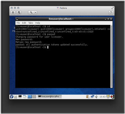
6. Set the password for the liveuser
We are currently logged in as the liveuser standard user account. The user account has no password by default, so we will set a password for it. This step is a prerequisite for upcoming tasks. Run the following command from LXTerminal:

[liveuser@localhost]$ passwd

Changing password for user liveuser.

New password: Pa$$worD1

Retype new password: Pa$$worD1

passwd: all authentication tokens updated successfully.

clip_image003

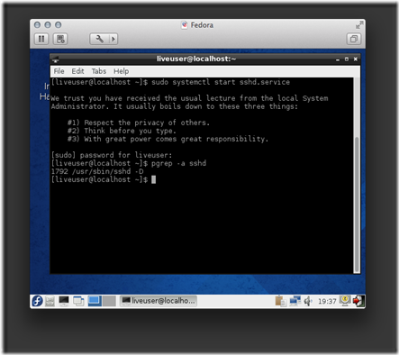
7. Start the SSH Server
Our next task is to start the SSH Server daemon as we will need to enable remote access to the Linux VM. Run the following command fromLXTerminal:

[liveuser@localhost]$ sudo systemctl start sshd.service

...

[sudo] password for liveuser: Pa$$worD1

Verify the daemon process has started and is running. Run the following command from LXTerminal:

[liveuser@localhost]$ pgrep -a sshd

1792 /usr/sbin/sshd -D

clip_image004

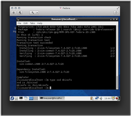
8. Download and install software packages
A couple of packages will need to be installed for the repack.v4.1.sh script to be able to create the bootable Cisco ASA ISO image file. Run the following command from LXTerminal:

[liveuser@localhost]$ sudo yum -y install vim-common mkisofs

...

Installed:

vim-common.i686 2:7.4.027-2.fc20

Dependency Installed:

vim-filesystem.i686 2:7.4.027-2.fc20

Complete!

Verify the packages have been successfully installed by running the following command from LXTerminal:

[liveuser@localhost]$ type xxd mkisofs

xxd is /bin/xxd

mkisofs is /bin/mkisofs

clip_image005

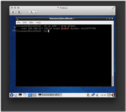
9. Get the IP configuration for the Fedora Linux VM
Your virtual machine will likely have a different dynamic IP address, so make sure to substitute the value in upcoming examples. Run the following command from LXTerminal:

[liveuser@localhost]$ ip addr | grep global

inet 192.168.217.145/24 scope global dynamic eno16777736

clip_image006

10. Transfer files from the Mac host to the Fedora Linux VM
Now that we have the IP address for the Linux VM guest, we can establish a scp connection and transfer the files from our Mac host to the remoteLinux VM guest. Run the following commands from Terminal:

$ cd $HOME/Documents/ASAVM

$ scp * liveuser@192.168.217.145:Documents

The authenticity of host '192.168.217.145 (192.168.217.145)' can't be established.

RSA key fingerprint is 62:38:a6:32:6b:d4:90:4a:7c:d8:10:b3:0c:85:d1:a5.

Are you sure you want to continue connecting (yes/no)? yes

Warning: Permanently added '192.168.217.145' (RSA) to the list of known hosts.

liveuser@192.168.217.145's password: Pa$$worD1

asa842-k8.bin 100% 24MB 24.0MB/s 00:01

repack.v4.1.sh 100% 4308 4.2KB/s 00:00

11. Create a SSH session to the Fedora Linux VM
Instead of continually entering commands in LXTerminal, within the virtual machine console, we will now simply establish a ssh session and enter the commands in our local Mac Terminal application. Run the following command from Terminal:

$ ssh liveuser@192.168.217.145

liveuser@192.168.217.145's password: Pa$$worD1

12. Run the repack.v4.1.sh script on the Fedora Linux VM (via SSH)
Run the following commands from Terminal:

[liveuser@localhost]$ cd $HOME/Documents

[liveuser@localhost]$ chmod +x repack.v4.1.sh

[liveuser@localhost]$ sudo ./repack.v4.1.sh ./asa842-k8.bin

[sudo] password for liveuser: Pa$$worD1

Repack script version: 4.1

Detected syslinux/cdrtools - ISO will be created

1359344+0 records in

1359344+0 records out

1359344 bytes (1.4 MB) copied, 2.4332 s, 559 kB/s

23697936+0 records in

23697936+0 records out

23697936 bytes (24 MB) copied, 97.922 s, 242 kB/s

/tmp/tmp.OFsCQZsGYc /home/liveuser/Documents

gzip: /home/liveuser/Documents/asa842-initrd-original.gz: decompression OK, trailing garbage ignored

114476 blocks

114476 blocks

114476 blocks

/home/liveuser/Documents

/tmp/tmp.KctycopD9w /home/liveuser/Documents

I: -input-charset not specified, using utf-8 (detected in locale settings)

Size of boot image is 4 sectors -> No emulation

21.05% done, estimate finish Wed Jan 8 22:46:41 2014

42.01% done, estimate finish Wed Jan 8 22:46:41 2014

63.01% done, estimate finish Wed Jan 8 22:46:41 2014

83.97% done, estimate finish Wed Jan 8 22:46:41 2014

Total translation table size: 2048

Total rockridge attributes bytes: 0

Total directory bytes: 2048

Path table size(bytes): 26

Max brk space used 0

23823 extents written (46 MB)

/home/liveuser/Documents

13. Verify the result
Four new files have been created in the directory. Run the following command from Terminal to confirm:

[liveuser@localhost]$ ll -h

-rw-r--r--. 1 root root 23M Jan 8 22:46 asa842-initrd.gz

-rw-r--r--. 1 root root 23M Jan 8 22:46 asa842-initrd-original.gz

-rw-r--r--. 1 liveuser liveuser 24M Jan 8 22:20 asa842-k8.bin

-rw-r--r--. 1 root root 1.3M Jan 8 22:44 asa842-vmlinuz

-rw-r--r--. 1 root root 47M Jan 8 22:46 asa.iso

-rwxr-xr-x. 1 liveuser liveuser 4.3K Jan 8 22:20 repack.v4.1.sh

We are finished with the interactive Linux portion, so close the ssh session to the the Fedora Linux VM. Run the following command fromTerminal:

[liveuser@localhost]$ exit

logout

Connection to 192.168.217.145 closed.

14. Transfer the asa.iso file from the Fedora Linux VM to the Mac
Run the following command from Terminal:

$ scp liveuser@192.168.217.145:Documents/asa.iso $HOME/Documents/ASAVM

liveuser@192.168.217.145's password: Pa$$worD1

asa.iso 100% 47MB 23.3MB/s 00:02

Verify the asa.iso file has been transferred to the local Mac file system. Run the following command from Terminal:

$ ls -lh $HOME/Documents/ASAVM

total 144456

-rw-r--r-- 1 marc staff 47M Jan 13 18:04 asa.iso

-rw-r--r-- 1 marc staff 24M Jan 13 17:48 asa842-k8.bin

-rw-r--r-- 1 marc staff 4.2K Jan 13 17:50 repack.v4.1.sh

The use of the Fedora Linux VM is complete. We can now shut down the Fedora Linux virtual machine in VMware Fusion.

15. Create the Cisco ASA virtual machine (VM)
We are ready to create the base Cisco ASA VM with the following steps:

1. Open the VMware Fusion application.

2. Select File -> New... from the menu.

3. Select Install from disc or image.

4. Click the Continue button.

5. Click the Use another disc or disc image... button.

6. Navigate to and select the asa.iso disc image.

7. Click the Open button.

8. Click the Continue button.

9. On the Choose Operating System screen, select Linux -> Other Linux 2.6x kernel.

10. Click the Continue button.

11. Click the Customize Settings button.

12. Name the virtual machine package as ASAVM.

13. Click the Save button to save the virtual machine in the default Virtual Machines folder.

16. Edit the virtual hardware for ASAVM
Make the following modifications in the Settings window: 

Component

Value

Processors

1 processor core

Memory

1024 MB

Network Adapter

Bridged Networking: Ethernet1

Network Adapter 2

Custom: Private to my Mac

Hard Disk (IDE)

0.50 GB

CD/DVD (IDE)

asa.iso

Sound Card

Remove Sound Card

USB & Bluetooth

Remove USB Controller

Printer

Remove Printer Port

# 16.1 Virtual Network Adapters
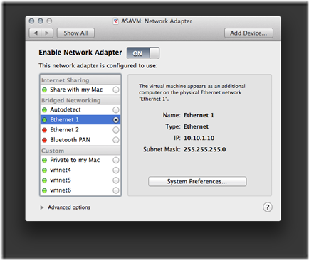
I've only tested Bridged Networking with a wired (i.e., no Wi-Fi) Ethernet connection. As newer Mac laptops don't have a physical Ethernet port, the StarTech USB31000S (Black) | USB31000SW (White) is a viable solution. For my labs that use a Cisco ASA as an Internet edge device, I define the first virtual network adapter as the logical outside interface that connects to the physical network.

clip_image007

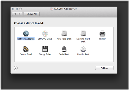
The virtual machine includes a single virtual network adapter by default. On the main Settings screen for the virtual machine, click the Add Device... button to add another Network Adapter device.

clip_image008

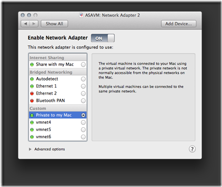
The second virtual network adapter will be set to Private to my Mac (VMnet1). For my labs that use a Cisco ASA as an edge device, I define the second virtual network adapter as the logical inside interface that connects to the virtual GNS3 network.

clip_image009

# 16.2 Virtual Hard Disk
Set the values for the following attributes of the virtual hard disk:

· Disk size: 0.50 GB

· Bus type: IDE

· Check Pre-allocate disk space

· Uncheck Split into multiple files

· Click the Apply button.

clip_image010

17. Edit the ASAVM configuration file
Close the VMware Fusion application before executing the steps in this section. 
Some settings can't be configured with the GUI, so we will need to directly edit the ASAVM .vmx (virtual machine configuration) file. My ASAVM virtual machine is located in the default VMware Fusion folder (directory), so I would edit the file with the following command from Terminal:

$ nano $HOME/Documents/Virtual\ Machines.localized/ASAVM.vmwarevm/ASAVM.vmx

# 17.1 Virtual Network Adapters
As you recall, we have two virtual network adapters configured for ASAVM. An issue is the model type is incorrect, so the Cisco ASA software won't recognize them upon boot. We can rectify this with the following steps:

· Locate the line with the ethernet0.present = "TRUE" statement.

· Insert a line directly below it with the ethernet0.virtualDev = "e1000e" statement.

...

ethernet0.present = "TRUE"

ethernet0.virtualDev = "e1000e"

ethernet0.connectionType = "custom"

ethernet0.wakeOnPcktRcv = "FALSE"

ethernet0.addressType = "generated"

ethernet0.linkStatePropagation.enable = "TRUE"

...

The previous steps will need to be repeated (substitute the vNIC index number) for every virtual network adapter attached to the virtual machine. So to complete my configuration, I would also insert the statement for my second virtual network adapter.

...

ethernet1.present = "TRUE"

ethernet1.virtualDev = "e1000e"

ethernet1.connectionType = "hostonly"

ethernet1.wakeOnPcktRcv = "FALSE"

ethernet1.addressType = "generated"

...

# 17.2 Virtual Serial Port
Just like with a physical Cisco ASA appliance, we can connect to our ASAVM with a console port connection. This is very similar to how we interface with our virtual routers in GNS3 (Dynamips). The following steps will create a virtual serial port that will allow us to emulate a console port connection via telnet.

· Locate the line with the serial0.present = "FALSE" statement.

· Change the value from FALSE to TRUE to enable it.

· Add some more statements to define the properties of the virtual component.

...

serial0.present = "TRUE"

serial0.yieldOnMsrRead = "TRUE"

serial0.fileType = "network"

serial0.fileName = "telnet://127.0.0.1:3456"

...

We are finished configuring the .vmx file, so lets save (control + o) the file, press the enter key to confirm, then exit (control + x) the nano text editor. 
18. Start ASAVM
Reopen the VMware Fusion application and start the ASAVM virtual machine. Press the enter key at the boot: prompt, within the ASAVM virtual console, to load the ASA.

19. Virtual console port connection to ASAVM
Remember we need to emulate a console port connection via telnet, so enter the following command from Terminal:

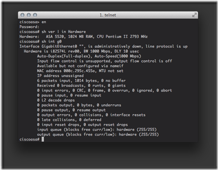
$ telnet 127.0.0.1 3456

clip_image011

20. Lab integration
Your virtual machine should be up and running, but a network device serves little purpose unless it's actually connected to a network. Check out my Implement a Multivendor OSPF Lab with GNS3 and VMware Fusion post for a practical example.

Posted 14th January by Marc Weisel

Labels: Cisco GNS3 Linux Mac SSH VMware

Taken From: http://binarynature.blogspot.pt/2014/01/create-cisco-asa-vmware-fusion.html
More Info at: http://7200emu.hacki.at/viewtopic.php?t=9074