Wednesday, September 30, 2015

Cisco - EEM Scripts Examples (TSHOOT)

EEM is a very useful tool to troubleshoot occasional, sporadic CPU spikes that are short-lived and difficult to troubleshoot manually with the command line interface. This is an example of CPU spikes:

Switch#show process cpu history
<snip>
    11111822511   11 111277711111 124111  11 1211111112161116
    143342171209994090111878458239607111981270283361362429475
100
90
80      *               ***
70      *               ***                                *
60      *               ***                            *   *
50      *  *            ***        *                   *   *
40      *  *            ***        *                   *   *
30      * **            ***        *                   *   *
20      ****           **** **   ***         **  *  ** ** **
10 *********************************************************
   0....5....1....1....2....2....3....3....4....4....5....5....6....6....7.
             0    5    0    5    0    5    0    5    0    5    0    5    0
                   CPU% per hour (last 72 hours)
                  * = maximum CPU%   # = average CPU%

This section includes several examples of the use of EEM scripts to monitor CPU utilization. Catalyst 2960 and 3750 switches allow EEM to use non-volatile RAM (NVRAM); Catalyst 4500 switches allow EEM to write to bootflash; and Catalyst 6500 switches allow EEM to use disk0 and sup-bootdisk.

Email Alerts

This script emails an alert when CPU utilization goes above 50 percent. The body of the email is the output of theshow process cpu sorted command.
event manager applet highcpu
  event snmp oid 1.3.6.1.4.1.9.9.109.1.1.1.1.3.1 get-type exact entry-op ge
entry-val 50 poll-interval 0.5
action 1.0 cli command "enable"
  action 2.0 cli command "show proc cpu sorted"
  action 3.0 mail server "192.168.1.1" to "user-to@domain.com" from "user-from@domain.com"
subject "High CPU Alert" body "$_cli_result"

The definitions of italicized variables are:

  • highcpu - name of the event manager applet/script
  • 1.3.6.1.4.1.9.9.109.1.1.1.1.3.1 - Object identifier (OID) for polling the total CPU utilization of the route processor (RP)
  • 50 - CPU utilization that triggers the script
    poll-interval 0.5 - Frequency (every 0.5 seconds) the script monitors the CPU
  • 192.169.1.1 - IP of the mail server

      Append Output to Local File

      This script appends required outputs to a file in the local file system. Replace file system with the appropriate file system on the switch.
      event manager scheduler script thread class default number 1 
      event manager applet High_CPU
      event snmp oid 1.3.6.1.4.1.9.9.109.1.1.1.1.3.1 get-type exact entry-op ge
      entry-val 50 poll-interval 0.5
      action 0.0 syslog msg "High CPU DETECTED. Please wait - logging Information
      to file system:high_cpu.txt"
      action 0.1 cli command "enable"
        action 0.2 cli command "show clock | append file system:high_cpu.txt"
        action 1.2 cli command "term length 0"
        action 1.3 cli command "show process cpu sorted | append file system:high_cpu.txt"
        action 1.4 cli command "show log | append file system:high_cpu.txt"
        action 1.5 cli command "show interfaces | append file system:high_cpu.txt"
        action 1.6 cli command "term length 24"

      Append Output to Local File and Remove Script

      This script appends the output of the show process cpu sorted command to a file in the local file system, then removes itself once completed. Replace file system with the appropriate file system on the switch.
      event manager scheduler script thread class default number 1 
      event manager applet High_CPU
      event snmp oid 1.3.6.1.4.1.9.9.109.1.1.1.1.3.1 get-type exact entry-op gt
      entry-val 50 poll-interval 0.5
      action 0.0 syslog msg "High CPU DETECTED. Please wait - logging Information
      to flash:high_cpu.txt"
        action 0.1 cli command "enable"
        action 0.2 cli command "term exec prompt timestamp"
        action 1.3 cli command "show process cpu sorted | append file system:high_cpu.txt"
        action 1.4 cli command "show process cpu sorted | append file system:high_cpu.txt"
        action 1.4 cli command "show process cpu sorted | append file system:high_cpu.txt"
        action 5.1 syslog msg "Finished logging information to file system:high_cpu.txt..."
        action 5.1 syslog msg "Self-removing applet from configuration..."
        action 5.2 cli command "term no exec prompt timestamp"
        action 9.1 cli command "configure terminal"
        action 9.2 cli command "no event manager applet High_CPU"
        action 9.3 cli command "end"

      Collect Output and Write to Local File

      This script uses a syslog-based trigger in order to run and collect required outputs and write those outputs to the local file system. Replace file system with the appropriate file system on the switch.
      process cpu threshold type total rising 70 interval 15 
      event manager applet DETECT_CPU
      event syslog pattern ".*SYS-1-CPURISINGTHRESHOLD.*"
      action 1 cli command "en"
      action 2 cli command "show clock | append file system:cpuinfo"
      action 3 cli command "show proc cpu sort | append file system:cpuinfo"
      action 4 cli command "show line | append file system:cpuinfo"

      Monitor CPU Utilization on Modular IOS

      The Cisco EEM can also be used to monitor CPU utilization on modular IOS. Because of the differences in how the CPU is monitored on modular IOS, you can use the Simple Network Management Protocol (SNMP) OID (1.3.6.1.4.1.9.9.109.1.1.1.1.3.1) in order to check CPU utilization by the IOS base process.

      This script uses the OID as a trigger and writes required outputs to the local file system. Replace file system with the appropriate file system on the switch.

      event manager scheduler script thread class default number 1
      event manager applet High_CPU
      event snmp oid 1.3.6.1.4.1.9.9.109.1.1.1.1.10.1  get-type exact entry-op ge
      entry-val 50 poll-interval 0.5
        action 0.0 syslog msg "High CPU DETECTED. Please wait - logging Information
      to file system:high_cpu.txt"
        action 0.1 cli command "enable"
        action 0.2 cli command "show clock | append file system:high_cpu.txt"
        action 1.2 cli command "term length 0"
        action 1.3 cli command "show process cpu sorted | append file system:high_cpu.txt"
        action 1.4 cli command "show log | append file system:high_cpu.txt"
        action 1.5 cli command "show interfaces | append file system:high_cpu.txt"
        action 1.6 cli command "term length 24"

      Remove Script

      Enter this command in order to remove an EEM script:
      Switch(config)#no event manager applet applet 
    • Based On: http://www.cisco.com/c/en/us/support/docs/switches/catalyst-6500-series-switches/116141-trouble-eem-scripts-00.html
      Contributed by Cisco Engineers: Shashank Singh and Saurav Lahiri

      Saturday, September 26, 2015

      Linux - PPTP VPN Server (via GUI on Ubuntu)


      How to Setup a “Split Tunnel” VPN (PPTP) Client on Ubuntu 10.04

      Sometimes you need to use a VPN connection to grant access to remote network resources and for that you use a VPN, but if you don’t want all of your client traffic to go through the VPN link, you’ll need to setup your VPN to connect in a “split tunnel” mode. Here’s how to do it on Ubuntu.

      Note: make sure that you’ve read our article covering how to setup a VPN server for Debian-based Linux, which also covers configuring the Windows client.


      Split what the what now?

      The “split tunnel” term refers to the fact that the VPN client creates a “tunnel” from the client all the way to the server for “private” communication.

      Traditionally the VPN connection is set up to create “the tunnel” and once it is up all the client’s communication is routed through that “tunnel”. this was good back in the day when the VPN connection had a couple of goals that overlapped and complimented each other:

      • The connection was meant to grant access for the road warrior from anywhere.
      • All of  the client’s connections need to be secured by means of  going through the corporate firewall.
      • The client computer must not be able to connect a potentially malicious network with the corporate network.

      The way the VPN connection of the time achieved this goal, was to set the “default gateway” or “route” of the client machine to the corporate VPN server.

      • This method, while affective for the above goals has several disadvantages, espeshelly if you are implementing the VPN connection only for the “grant access” point:
      • It will slow down the entire surfing experience of the client computer to the speed of the VPN server’s upload speed, which is usually slow.
      • It will disable access to local resources like other computers in the local network unless they are all connected to the VPN, and even then the access will be slowed down because it has to go all the way to the internet and come back.

      To overcome these shortcomings we will create a regular VPN dialer with one note worthy exception, that we will set the system to NOT use it as the “Default Gateway” or “route” when connected.

      Doing this will make it so that the client will use the “VPN tunnel” only for the resources behind the VPN server and will access the internet normally for everything else.


      Let’s get cracking

      The first step is to get into “Network connections” and then “Configure VPN”.

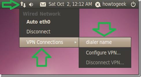
      One way you can do this is by clicking the desktop icon for networking as shown in the picture.

      clip_image001

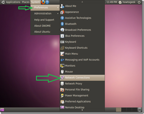
      Another way is to go to “System” > “Preferences” > “Network Connections”.

      clip_image002

      Once your on the “VPN” tab in the “Network connections” configurations window, click “Add”.

      clip_image003

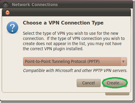
      On the next window we only need to click “Create”, as the default connection type of PPTP is what we want to use.

      clip_image004

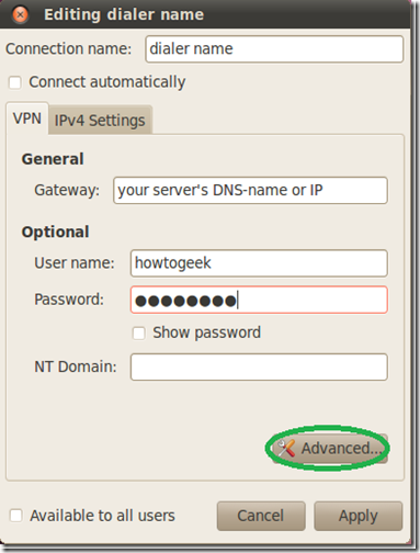
      In the next window give your dialer a name, fill in the gateway with your servers DNS-name or IP address as seen from the internet and fill in the user credentials.

      If you have used the “Setting up a VPN (PPTP) server on Debian” guide for the server setup or you are using this client for a DD-WRT PPTP server setup, you also need to enable the MPPE encryption options for authentication.

      Click on “Advanced”.

      clip_image005

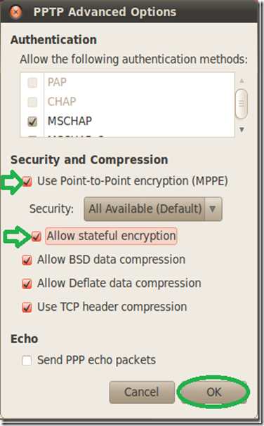
      On the “Advanced Options” window check the first checkbox for the MPPE option, then the second checkbox to allow stateful encryption and click “OK”.

      clip_image006

      Back on the main window, click the “IPv4 Settings” tab.

      clip_image007

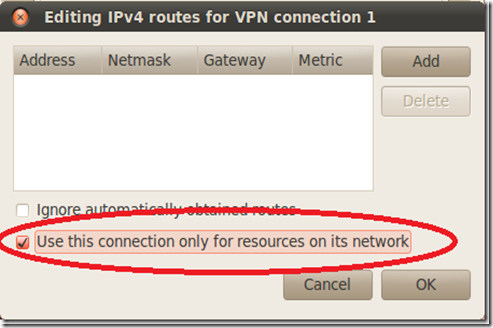
      On the routes configuration window check the checkbox of “Use this connection only for resources on its network”.

      clip_image008

      Activate the VPN connection client by clicking on the “Network connections” icon and selecting it.

      clip_image009

      That’s it, you can now access the resources on the VPN servers side as if you were on the same network while not sacrificing your download speed in the process…


      Taken From: http://www.howtogeek.com/51340/setting-up-a-split-tunnel-vpn-pptp-client-on-ubuntu-10-04/

      Friday, September 25, 2015

      Linux - PPTP VPN Server & Win XP/7 Client


      How to Setup a VPN (PPTP) Server on Debian Linux
      (also tested on the Raspberry Pi on Raspbian)

      VPN-ing into your server will allow you to connect to every possible service running on it, as if you were sitting next to it on the same network, without individually forwarding every port combination for every service you would like to access remotely.

      Using a VPN connection also has the upshot of, if desired, granting access to other computers on the network as if you where in it locally from anywhere across the internet.

      While not the most secure of the VPN solutions out there, PPTP is by far the simplest to install, configure and connect to from any modern system and from windows specifically as the client is a part of the OS since the XP days and you don’t need to mess with certificates (like with L2TP+IPsec or SSL VPNs) on both sides of the connection.

      Did i get you interested? then let’s go :)


      Preface

      • You will need to forward port 1723 and the GRE protocol (47) from the internet to the server to enable the connection (not covered here).
      • You will see me use VIM as the editor program, this is just because I’m used to it… you may use any other editor that you’d like.~


      Server Setup

      Install the pptp server package:
          sudo aptitude install pptpd

      Edit the “/etc/pptpd.conf” configuration file:
          sudo vim /etc/pptpd.conf

      Add to it:
          option /etc/ppp/pptpd-options
          localip 192.168.1.5
          remoteip 192.168.1.234-238,192.168.1.245

      Where the “localip” is the address of the server, and the remoteip are the addresses that will be handed out to the clients, it is up to you to adjust these for your network’s requirements.

      Edit the “/etc/ppp/pptpd-options” configuration file:
          sudo vim /etc/ppp/pptpd-options

      Append to the end of the file, the following directives:
          ms-dns 192.168.1.1
          nobsdcomp
          noipx
          mtu 1490
          mru 1490

      here we are assuming that we are editing the pptpd default options config and adding to it, but if for some reason you start with a black “pptpd-options”, you will need to enter those defaults (based on a “pptpd-options” on Raspberry Pi Runing Raspbian):

      name pptpd

      # BSD licensed ppp-2.4.2 upstream
      # with MPPE only

      refuse-pap
      refuse-chap
      refuse-mschap

      # Require the peer to authenticate
      # itself using MS-CHAPv2

      require-mschap-v2

      # Require MPPE 128-bit encryption
      require-mppe-128


      # Making the peer appear to other
      # systems to be on the local ethernet

      proxyarp

      # Debian: do not replace the default route
      # with this you get split tunelling

      nodefaultroute

      # Create a UUCP-style lock file for
      # the pseudo-tty to ensure exclusive

      lock

      # Disable Van Jacobson compression
      novj
      nobsdcomp

      # Turn off logging to stderr
      nologfd

      to get more detail on each item check a default “pptpd-options” file it’s has quite some detail on each item.

      Where the IP used for the ms-dns directive is the DNS server for the local network your client will be connecting to and, again, it is your responsibility to adjust this to your network’s configuration.

      Edit the chap secrets file:
          sudo vim /etc/ppp/chap-secrets

      Add to it the authentication credentials for a user’s connection, in the following syntax:
          username <TAB> * <TAB> users-password <TAB> *

      Restart the connection’s daemon for the settings to take affect:
          sudo /etc/init.d/pptpd restart

      If you don’t want to grant yourself access to anything beyond the server, then you’re done on the server side.


      Enable Forwarding (optional)

      While this step is optional and could be viewed as a security risk for the extremely paranoid, it is my opinion that not doing it defeats the purpose of even having a VPN connection into your network.

      By enabling forwarding we make the entire network available to us when we connect and not just the VPN server itself. Doing so allows the connecting client to “jump” through the VPN server, to all other devices on the network.

      To achieve this we will be flipping the switch on the “forwarding” parameter of the system.

      Edit the “sysctl” file:
          sudo vim /etc/sysctl.conf

      Find the “net.ipv4.ip_forward” line and change the parameter from 0 (disabled) to 1 (enabled):
          net.ipv4.ip_forward=1

      You can either restart the system or issue this command for the setting to take affect:
         sudo sysctl -p

      With forwarding enabled, all the server side settings are prepared.

      We recommend using a “Split Tunnel” connection mode for the VPN client.

      A more in depth explanation about the recommended “Split Tunnel” mode, as well as instructions for Ubuntu Linux users can be found in the “Setting up a “Split Tunnel” VPN (PPTP) Client on Ubuntu 10.04” guide.

      For windows users, follow the guides below to create the VPN client on your system.


      PPTP VPN Dialer Setup on XP (split tunnel)

      We will create a regular VPN dialer with one note worthy exception, that we will set the system to NOT use it as the “Default Gateway” when connected.

      Skipping this step will limit the connecting computer’s surfing speed to the VPN server’s upload speed (usually slow) because all of it’s traffic would be routed through the VPN connection and that’s not what we want.

      We need to start the connection wizard, so we will go to control panel.

      Go to “Start” and then “Control Panel”.

      clip_image001

      *If your system is setup with the “Classic Start Menu” you need to just point on the “Control Panel” icon and then select “Network Connections”.

      In “Control Panel” double click “Network Connections”.

      clip_image002

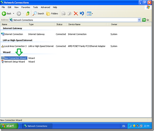
      Double click “New Connection wizard”.

      clip_image003

      In the “New Connection wizard” welcome screen click “Next”.

      clip_image004

      Select the “Connect to the network at my workspace” option and then “Next”.

      clip_image005

      Select the “Virtual Private Network connection” option and then “Next”.

      clip_image006

      Give a name to the VPN connection.

      clip_image007

      Type in the name of your VPN servers DNS-name or IP address as seen from the Internet.

      clip_image008

      Optionally You may choose to “Add a shortcut to the desktop” and “Finish”.

      clip_image009

      Now comes the tricky part, it is vitally important you do NOT try to connect now and go into the dialer’s “Properties”.

      clip_image010

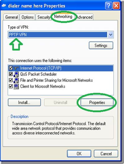
      Go to the networking tab and change the “Type of VPN” to “PPTP VPN” as shown in the picture below (this is optional but will shorten the time it takes to connect) then go into “Properties”.

      clip_image011

      On the next window go into “Advance” without changing anything else.

      clip_image012

      On the next window, uncheck the “Use default gateway on remote network” option.

      clip_image013

      Now enter the connection’s credentials as you set them on the server and connect.

      clip_image014

      That’s it, you should now be able to access all the computers on your network from the XP client… Enjoy.


      PPTP VPN Dialer Setup on Win7 (split tunnel)

      We will create a regular VPN dialer with one note worthy exception, that we will set the system to NOT use it as the “Default Gateway” when connected.

      Skipping this step will limit the connecting computer’s surfing speed to the VPN server’s upload speed (usually slow) because all of it’s traffic would be routed through the VPN connection and that’s not what we want.

      We need to start the connection wizard, so we will go to the “Network and Sharing Center”.

      Click the network icon in the system tray and then “Open Network and Sharing Center”

      clip_image015

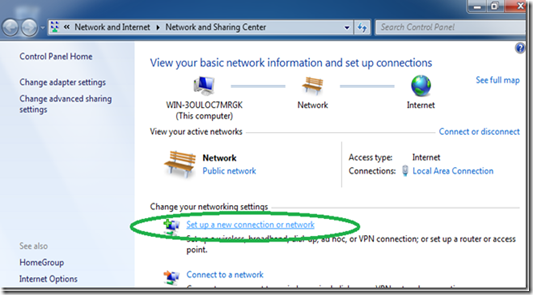
      In the Network center click on “Set up a new connection or network”.

      clip_image016
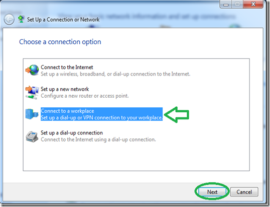
      Select “Connect to a workplace” and then “Next”.
      clip_image017
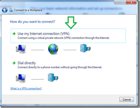
      Click on the first option of “Use my Internet connection (VPN)”.

      clip_image018
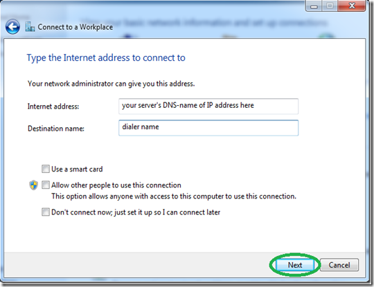
      Set the address of your VPN server as seen from the internet either by DNS-name or IP.

      clip_image019
      Even though it won’t connect now because we stil need to go into the dialer’s properties, Set the username and password and hit connect.

      clip_image020
      After the connection will fails to connect (that’s normal), click on “Set up the connection anyway”.

      clip_image021
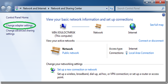
      Back in the “Network Center”, click on “Change adapter settings”.

      clip_image022
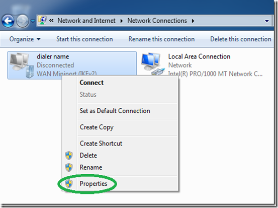
      Find the dialer we have just created, right click it and select “Properties”.

      clip_image023

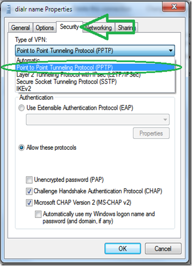
      While its optional, for a faster connecting dialer, set the “type” of VPN to PPTP under “the “Security” tab.
      clip_image024

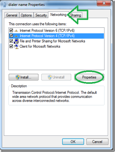
      Go to the “Networking” tab, select the IPv4 protocol and go into it’s properties.

      clip_image025

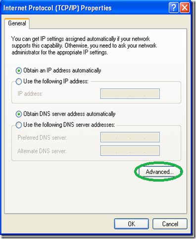
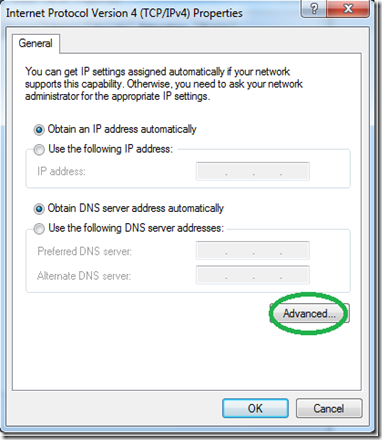
      In the next window, click “Advance” without changing anything else.

      clip_image026

      On the next window, uncheck the “Use default gateway on remote network” option.

      clip_image027

      Now enter the connection’s credentials as you set them on the server and connect.

      clip_image028

      That’s it, you should now be able to access all the computers on your network from the win7 client.

      Note: Be sure and read our guide to setting up a VPN client for Ubuntu Linux.

      Based On; http://www.howtogeek.com/51237/setting-up-a-vpn-pptp-server-on-debian/

      Monday, September 21, 2015

      Windows – PPTP VPN Server (+IOS Client +Port Forward)

      Here we are going to show you how to set up a Home VPN by using a user PC running windows, so that you can access you home network form almost every device. 


      VPN Server (Windows – User Edition)

      The configuration is identical in Windows 7/8/10 (maybe on XP to)

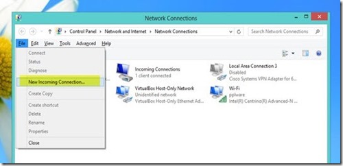
      To create the VPN Server you should go to Control Panel > Network and Internet and then Network Connections .

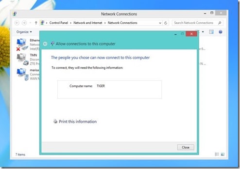
      Ther you should press the ALT key so that the options bar appears, next you should go to File > New Incoming Connection

      clip_image002

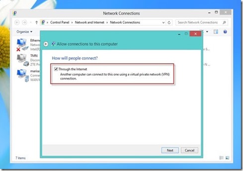
      Select or add the users that can access the VPN

      clip_image003

      clip_image004

      (Optional) In case that you want to define the addresses to give to the remote machines you should click on Properties

      clip_image005

      clip_image006

      Now you have a PPTP VPN Server that receives the tunnels and forwards the traffic to the Lan, where it’s connected.


      Port Forwarding

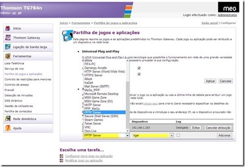
      On your home router you need to forward PPTP trafic to your internal PPTP VPN Server.

      Your need to forward:

      • PPTP Port 1723: Router Public IP ==> Internal PPTP Server
      • GRE Protocol (Protocol 47) : Router Public IP ==> Internal PPTP Server

      clip_image007


      VPN Client

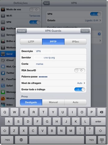
      Almost every system has a PPTP client already installed (IPhone / Android / Windows / Linux)

      For the IPhone just do:

      • Description / Descrição: Brief description of the connection
      • Server / Servidor: Router Public IP / Name (DynDNS like no-ip)
      • Account / Conta: User Name
      • Password / Palavra-passe: Password
      • clip_image009

      for the other systems the configuration is also pretty straight forward

      Based on:

      Sunday, August 30, 2015

      Linux – SSH Reverse Tunnel to Bypass NAT

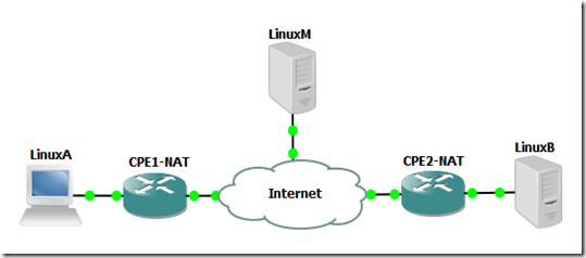
      Have you ever wanted to reach a server via some application, for example ssh, but you couldn’t because the remote computer (LinuxB) was beind NAT, and you didn’t had access to the router (CPE2-NAT) to add a port forwarding:Top_Prob

      but if you add another server with a Public IP (LinuxM) in the midlle you can set up a Reverse SSH Tunel between the destination (LinuxB) and the server in the middle (LinuxM) that will forward conection to a local port on LinuxM to the destination port  on LinuxB via the established ssh session that has the reverse/remote tunel configured.

      Top_Solution

      To test the Reverse SSH Tunel to bypass NAT I’m going to do a proof of concept (POC), with some linux (Ubuntu) machines with private addressing, the cenario looks like this:

      Topologia_POC1


      Linux_M – Middleman
      ===========================================================

      ## Hostname ##
      sudo nano /etc/hostname
      LinuxM
      hostname LinuxM
      hostname

      sudo nano /etc/hosts
      127.0.1.1       LinuxM


      ## Interfaces ##
      sudo ifdown eth0                                                                 
      sudo ifconfig eth0 192.168.1.254 netmask 255.255.255.0
      sudo ifup eth0                                      

      sudo ifdown eth1                                                                 
      sudo ifconfig eth1 172.16.1.254 netmask 255.255.255.0
      sudo ifup eth1


      ## IP Forwarding (Routing) ##
      sudo  sysctl -w net.ipv4.ip_forward=1


      ## Activate Gateway Ports ##
      sudo nano /etc/ssh/sshd_config
      GatewayPorts yes
      sudo service ssh stop
      sudo service ssh start

      #####################################################
      # When you forward a TCP port (either locally or
      # remotely), by default SSH only listens for
      # connections to the forwarded port on the loopback
      # address (localhost, 127.0.0.1). This means only
      # other programs running on the same host as the
      # listening side of the forwarding can connect to
      # the forwarded port. This is a security feature,
      # since there is no authentication applied to such
      # connections. Also, such a forwarded connection is
      # potentially insecure, since a portion of it is
      # carried over the network in a plain TCP connection
      # and not protected by SSH.
      #####################################################


      Linux_B – Destination
      ===========================================================

      ## Hostname ##
      sudo nano /etc/hostname
      LinuxB
      hostname LinuxB
      hostname

      sudo nano /etc/hosts
      127.0.1.1       LinuxB


      ## Interface ##
      sudo ifdown eth0                                                                 
      sudo ifconfig eth0 172.16.1.1 netmask 255.255.255.0
      sudo ifup eth0


      ## Route (default) ##
      sudo route add default gw 172.16.1.254 eth0


      ## Reverse/Remote SSH Tunnel ##
      ssh -R 10002:localhost:22 lubuntu@172.16.1.254

      ######################################################
      # This sets up the reverse/remote ssh tunnel
      # between the destination (LinuxB) and the server
      # in the middle (LinuxM) that will forward connection
      # on the local port 10002 on LinuxM to the
      # destination port 22 LinuxB via the established
      # ssh session that has the reverse/remote tunel
      # configured.
      #
      # After this command you will have the reverse/remote
      # ssh thunnel configured and the bash/CLI of LinuxM.
      #
      # YOU MUST MAINTAIN THE BASH/CLI OF LinuxM ON LinuxB
      # VIA SSH, FOR THE FORWARDING/TUNNELING TO WORK
      #####################################################

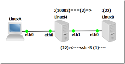
      At this point you have this:

      Topologia_POC2

      the reverse/remote ssh tunnel wating for a connection on LinuxM on port 10002 to forward LinuxB on port 22 (ssh)


      Linux_A – Client
      ===========================================================

      ## Hostname ##
      sudo nano /etc/hostname
      LinuxA
      hostname LinuxA
      hostname

      sudo nano /etc/hosts
      127.0.1.1       LinuxA

       
      ## Interface ##
      sudo ifdown eth0                                                                 
      sudo ifconfig eth0 192.168.1.1 netmask 255.255.255.0
      sudo ifup eth0


      ## Route (default) ##
      sudo route add default gw 192.168.1.254 eth0   


      ## Connect LinuxM (will forward to LinuxB) ##
      ## Gateway Ports = ON on LinuxM                ##

      ssh lubuntu@192.168.1.254 -p 10002

      or

      ## Connect LinuxM (will not forward to LinuxB) ##
      ## Gateway Ports = OFF on LinuxM                      ##

      ssh lubuntu@192.168.1.254         
      ssh lubuntu@localhost -p 10002

      ######################################################
      # Assuming the "Gateway Ports" is OFF, then the
      # reverse/remote ssh tunnel will only be accessible
      # on LinuxM locally
      #
      # So in the above commands we first connect via SSH
      # to LinuxM, and from there connect local ports of the
      # reverse/remote ssh tunnel so that it will forward
      # the connection on the local port 10002 of LinuxM
      # to the destination port 22 LinuxB
      #####################################################

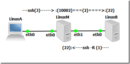
      At this point you have this (Gateway Ports = ON):

      Topologia_POC3 and you should be in the bash/CLI of LinuxB Sorriso


      Related Links: